Table of Contents
Advertisement
Quick Links
Advertisement
Table of Contents

Related Manuals for TRENDnet TV-IP322P


Summary of Contents for TRENDnet TV-IP322P
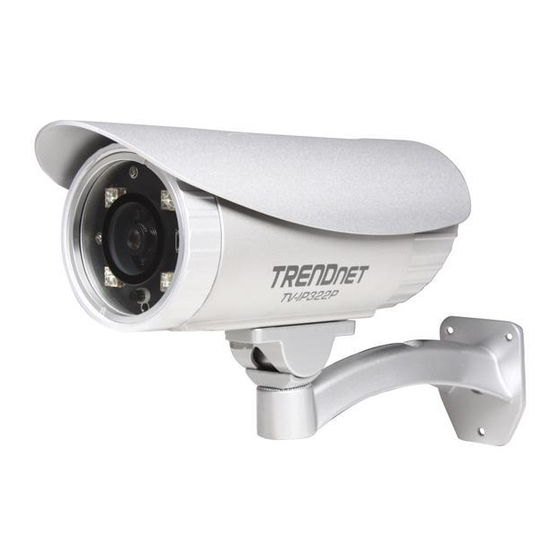
- Page 2 REFACE Thank you for purchasing the TV-IP322P SecurView™ Outdoor PoE Megapixel Day/Night Internet Camera, a standalone system that can be connected directly to an Ethernet or Fast Ethernet network. The camera is equipped with a 2-megapixel CMOS sensor, allowing you to capture high quality image with the resolution of up to 1280 x 1024.
-
Page 3: Chapter
This Advanced Installation Guide provides you with the instructions and illustrations on how to use your camera, which includes: Chapter 1 Introduction to Your Camera describes the features of the camera. You will also know the components and functions of the camera. Chapter 2 Hardware Installation helps you install the camera according to your application environment. -
Page 4: Table Of Contents
Contents R E F A C E H A P T E R N T R O D U C T I O N O U R A M E R A 1.1 C ..........5 HECKING THE ACKAGE ONTENTS 1.2 G .......... - Page 5 4.8 E ............58 VENT ONFIGURATION 4.9 T ................... 64 OOLS 4.10 RS-485 ................. 66 4.11 S SD C ............70 ETTING UP THE 4.12 I ................ 72 NFORMATION H A P T E R ™ P E C U R I E W O F T W A R E 5.1 I...
-
Page 6: Hapter
1.1 Checking the Package Contents Unpack the package and check the items contained in the package carefully. You should have the following: 1 x TV-IP322P 1 x Multi-Language Quick Installation Guide 1 x CD-ROM (Utility & User’s Guide) ... -
Page 7: Getting To Know The Camera
1.2 Getting to Know the Camera The Camera and the Shield Shield* is used to protect the camera during inclement weather. Lens Assembly with IR LEDs Connectors Power, Audio, Mic, GPIO, LAN Camera Stand * There are various positions of screw hole on the shield, allowing you to move the shield forward/backward according to your needs. - Page 8 The Connectors The camera's connectors are collected into a bundle of cable on the back panel of the camera, allowing you to connect the external devices in a well-ordered way while you are installing the camera onto the wall (or ceiling).
- Page 9 LAN: Plugs the provided Ethernet cable to connect to your local area network (LAN). The LAN port of the camera supports the NWay protocol so that the camera can detect the network speed automatically. - 8 -...
-
Page 10: Features And Benefits
1.3 Features and Benefits H.264/MPEG4/MJPEG Multi-codec Supported The camera provides you with excellent images by the H.264/MPEG4/ MJPEG multi-codec selectable technology, allowing you to adjust image size and quality, and bit rate according to the networking environment. High Resolution Surveillance Equipped with a megapixel CMOS sensor, the high performance camera is designed for your professional surveillance and security applications. - Page 11 Remote Control Supported By using a standard Web browser or the bundled SecurView™ Pro software application, the administrator can easily change the configuration of the camera via Intranet or Internet. In addition, the camera can be upgraded remotely when a new firmware is available.
- Page 12 automatically. This allows the camera to capture clear image whenever the environment light changed. PoE Supported PoE (Power over Ethernet) standard enables the camera to be powered by the Ethernet, which simplifies your surveillance system by eliminating the need of power outlet. The PoE camera features both stability and security, providing a cost-saving solution to your application of Internet camera.
-
Page 13: System Requirement
1.4 System Requirement Networking 10 Base-T Ethernet or 100Base-TX Fast Ethernet; Auto-MDIX. IEEE 802.3af PoE Accessing the Camera using Web Browser Platform Microsoft® Windows® 7/Vista/XP CPU Intel Pentium III 800MHz or above RAM 512MB ... -
Page 14: Hapter
HAPTER ARDWARE NSTALLATION - 13 -... -
Page 15: Assembling The Camera Mounting Bracket
2.1 Assembling the Camera Mounting Bracket Assemble the sun visor and camera mounting bracket to the camera by using the provided screws and washers, and then the camera can be mounted on the wall (or ceiling) securely through the three screw holes on the base of the holder. -
Page 16: Nstalling The Emory Ard
junction points of the connectors while you connect the cables or purchase a weatherproof cable/power cord protector. 2.3 Installing the Memory Card The camera provides a SD card slot that allows you to install the memory card (not included in the package) to store files. To install the memory card: 1. -
Page 17: Applications Of The Camera
2.4 Applications of the Camera The camera can be applied in multiple applications, including: Monitor local and remote places and objects via Internet or Intranet. Capture still images and video clips remotely. Upload images or send email messages with the still images attached. -
Page 18: Hapter
HAPTER CCESSING AMERA 3.1 Using IP Setup The camera comes with a conveniently utility, IP Setup, which is included in the Installation CD-ROM, allowing you to search the camera on your network easily. 1. Insert the Installation CD-ROM into your computer’s CD-ROM drive to initiate the Auto-Run program. - Page 19 2. Click the IP Setup from the Auto-Run menu screen. Then IP Setup Wizard will appear. Click “Next” when the Welcome to the IPSetup Setup Wizard appears. 3. Click “Browse” to choose the desired destination location. By default, the destination location is C:\Program Files\TRENDnet\IPSetup. Then Click “Next”. - 18 -...
- Page 20 4. Click “Next” to confirm the IPSetup software to be installed to the computer. 5. When the Installation Complete window appears, click “Finish”. - 19 -...
- Page 21 6. After installing the IPSetup utility, the application is automatically installed to your computer, and creates a folder in “Start \Program\TRENDnet\IPSetup”. 7. Click Start > Programs > TRENDnet > IPSetup, and then click IPSetup 8. The IPSetup window will appear. It will search the Camera within the same network.
- Page 22 Camera Display Area: It shows the connected camera(s) within the same network. By default, the IP setting on the Camera is set up DHCP. If you have DHCP server, the camera will automatic get the IP address from DHCP server. If you do not have DHCP server on your network, it will show the default IP as 192.168.10.30.
-
Page 23: Accessing To The Camera
3.2 Accessing to the Camera By default, the IP setting on the camera is set to DHCP. It is recommend to use IPSetup to find the camera’s IP address. Once you find the IP address of the camera, click Link to access the camera’s web page. If the camera cannot get the IP address from DHCP server, you can access the camera by manually entering the default IP address: 192.168.10.30... - Page 24 The Main screen will appear as below: The Main screen of the Web Configuration provides you with the useful information and functions, including: Live View/Setup Switch: Click the button to configure the camera.
- Page 25 Snapshot allows you to capture and save a still image. Browse allows you to assign the destination folder to store the video clips and still images. Talk allows you to speak out through the camera. Please note only one user is allowed to use this function at a time.
-
Page 26: Configuring The Ip Address Of The Computer
3.3 Configuring the IP Address of the Computer If you are failed to access to the camera, please check the IP address of your computer. When you connect the camera to your computer directly to proceed with configuration of the camera, you need to set up the IP addresses to be in the same segment for the two devices to communicate. -
Page 27: Hapter
HAPTER ONFIGURING AMERA 4.1 Using the Web Configuration You can access and manage the camera through the Web browser and the provided software application UltraView Pro. This chapter describes the Web Configuration, and guides you through the configuration of the camera by using the Web browser. -
Page 28: Using Smart Wizard
4.2 Using Smart Wizard The camera’s Smart Wizard lets you configure your camera easily and quickly. The wizard will guide you through the necessary settings with detailed instructions on each step. To start the wizard, click Smart Wizard in the left menu bar. Step 1. - Page 29 Step 2. IP Settings Setup the IP setting, DHCP, Static IP or PPPoE. Step 3. Email Settings Enter the mail server information. If you are using a free mails server, select the SSL and/or STARTTLS according to the mail server requirement. - 28 -...
- Page 30 Step 4. Confirm Settings Click Apply to finish the setting or click Prev to change the previous setting or click Cancel to disregard all setting. - 29 -...
-
Page 31: Basic Setup
4.3 Basic Setup The Basic menu contains three sub-menus that provide the system settings for the camera, such as the Camera Name, Location, Date & Time, and User management. - 30 -... - Page 32 4.3.1 Basic >> System Basic: This item allows you to assign the camera name and location. Camera Name: Enter a descriptive name for the camera, which will help you to identify the camera when you have multiple cameras on your network. By default, the camera name is set as the model number.
- Page 33 4.3.2 Basic >> Date & Time Date and Time: Enter the correct date and time for the camera. TimeZone: Select the proper time zone from the pull-down menu. Synchronize with PC: Select this option and click Apply. The date & time settings of the camera will be synchronized with the connected computer.
- Page 34 4.3.3 Basic >> User Administrator: To prevent unauthorized access to the camera’s Web Configuration, you are strongly recommend to change the default administrator password. Type the administrator password twice to set and confirm the password. General User User Name: Enter the user’s name you want to add to use the camera.
- Page 35 Guest User Name: Enter the guest’s name you want to add to use the camera. Password: Enter the password for the new guest. UserList: Display the existing guests of the camera. To delete a user, select the one you want to delete and click Delete. NOTE The “General User”...
-
Page 36: Network Settings
4.4 Network Settings The Network menu contains two sub-menus that provide the network settings for the camera, such as the IP Setting, DDNS Setting, and IP Filter. 4.4.1 Network >> Network IP Setting: This item allows you to select the IP address mode and set up the related configuration. - Page 37 Static IP: Select this option to assign the IP address for the camera directly. You can use IPFinder to obtain the related setting values. Enter the IP address of the camera. The default setting is 192.168.10.30. Subnet Mask Enter the Subnet Mask of the camera. The default setting is 255.255.255.0.
- Page 38 device interoperability. In addition, it supports port auto mapping function so that you can access the camera if it is behind an NAT router or firewall. Select the Enable option to enable this feature. Ports Number HTTP Port: The default HTTP port is 80. NOTE If the camera is behind an NAT router of firewall, the suggested port to be used is from 1024 to 65535.
- Page 39 Bonjour: The devices with Bonjour will automatically broadcast their own services and listen for services being offered for the use of others. If your browser with Bonjour, you can find the camera on your local network without knowing its IP address. The Apple Safari is already with Bonjour.
- Page 40 4.4.3 Network >> IP Filter The IP Filter setting allows the administrator of the camera to limit the users within a certain range of IP addresses to access the camera. To disable this feature, select the Disable option; otherwise, select the Accept option to assign the range of IP addresses that are allowed to access the camera, or select the Deny option to assign the range of IP addresses that are blocked to access the camera.
- Page 41 located within 192.168.10.50 ~ 192.168.10.80 will not be allowed to access the camera. IPv6: Enter the IP Address that is allowed to access the camera. Deny IPv4: Assign a range of IP addresses that are blocked to access the camera by entering the Start IP address and End IP address options.
-
Page 42: Setting Up Video & Audio
4.5 Setting up Video & Audio The Video & Audio menu contains four sub-menus that provide the video and audio settings for the camera. - 41 -... - Page 43 4.5.1 Video & Audio >> Camera Image Setting Black Level: Adjust the brightness level from 0 ~ 5. Brightness: Adjust the brightness level from 0 ~ 100. Saturation: Adjust the colors level from 0 ~ 100. Sharpness: Adjust the sharpness level from 0 ~ 100. Click Default to restore the default settings of the three options above.
- Page 44 4.5.2 Video & Audio >> Video H.264 Video Resolution: Select the desired video resolution from the four formats: SXGA, VGA, QVGA and QQVGA. The higher setting (VGA) obtains better video quality while it uses more resource within your network. Video Quality: Select the desired image quality from five levels: Lowest, Low, Medium, High, and Highest.
- Page 45 Frame Rate: Select Auto or a proper setting depending on your network status. MJPEG Video Resolution: Select the desired video resolution from the four formats: SXGA, VGA, QVGA and QQVGA. The higher setting (VGA) obtains better video quality while it uses more resource within your network.
- Page 46 4.5.3 Video & Audio >> Audio Camera Microphone In: Select the Enable option to enable the camera’s audio function, so that you can receive the on-site sound and voice from the camera. Camera Speaker Out: Select the Enable option to enable the camera’s external speaker function, so that the connected speaker can play the sound and voice through the camera.
- Page 47 4.5.4 Video & Audio >> Overlay / Mask This sub-menu is used to set the image overlay and mask feature of the camera. Image Overlay: This item allows you to set the image overlay. In the Image File option, click Browse to select the image file from your computer, and then click Upload.
- Page 48 NOTE The width and height of the input overlay graphic should be multiple of 4 at a maximum size of 43690 pixels, and in JPG or BMP (24-bit RGB) format. Privacy Mask: This item allows you to configure up to two mask areas.
- Page 49 For example, when you select the Include Date & Time and Include Text options and click Apply, you can see the related information displayed on the live view image when you click the button. - 48 -...
-
Page 50: Event Server Configuration
4.6 Event Server Configuration The Event Server menu contains four sub-menus that allow you to upload images to FTP, send emails that include still images, and store the images to a NAS system. When you complete the required settings for HTTP, FTP, Email, or Network Storage, click Test to test the related configuration is correct or not. - Page 51 4.6.1 Event Server Setting >> HTTP HTTP Notify For Motion Trigger Send the query parameter via an HTTP notification when an event is triggered. Host: Enter the IP of the HTTP server Port: Enter the Port number of the HTTP server User Name: Enter the username of the HTTP server Password: Enter the password of the HTTP server Query: Enter the query parameter for the request if necessary...
- Page 52 Example: Host: 192.168.10.1 Port: 80 Query: xxx.cgi?name1=value1&name2=value2 Ex: cgi/event.cgi?status=#s&time=#t&model=modelname Result: http://192.168.10.1:80/cgi/event.cgi?status=#s&time=#t&model= modelname 4.6.2 Event Server Setting >> FTP Host Address: Enter the IP address of the target FTP server. Port Number: Enter the port number used for the FTP server. User Name: Enter the user name to login into the FTP server.
- Page 53 FTP Upload with: Select upload to FTP with one snapshot image or a series image in pre-event/post-event time when event triggered. NOTE Due to the network environment, the camera may not upload number of images that you set. 4.6.3 Event Server Setting >> Email ...
- Page 54 SMTP Port: Assign the SMTP port in the text box. The default SMTP port is 25. If the mail server requires an encrypted connection, you should check the SSL option. SSL / STARTTLS: Most free email services require an encrypted connection.
- Page 55 4.6.4 Event Server Setting >> Network Storage Network Storage Samba Server Address: Enter the IP address of the Network Storage server. Share: Assign the folder on the Network Storage server to share the files to users. Path: Assign the path for uploading the files on the Network Storage server.
- Page 56 Encode Format: Select MPEG4 or H.264 as the encode format while recording. File Format: Select MP4 or AVI as the file format while recording. NOTE The recorded video files in Network Storage are enclosed by AVI format without audio. 4.6.5 Event Server Setting >> Instant Message The camera supports the Jabber IM service, so that you can send an instant message once you have a Jabber account.
- Page 57 Instant Message Jabber ID: Enter your user ID to login into the Jabber IM service. Jabber Password: Enter the password to login into the Jabber IM service. Manually Specify Server Host/Port: Select the Enable option to manually configure the Jabber server settings. Jabber Server Address: Enter the Jabber server address manually.
-
Page 58: Motion Detect
4.7 Motion Detect The Motion Detect menu contains the command and option that allow you to enable and set up the motion detection feature of the camera. The camera provides three detecting areas. To enable the detecting area, select Window 1/2/3 from the pull-down list, and then select Enable. -
Page 59: Event Configuration
4.8 Event Configuration The Event Config menu contains five sub-menus that provide the commands to configure event profiles. - 58 -... - Page 60 4.8.1 Event Configuration >> General Setting General Snapshot/Recording Subfolder: You can assign a descriptive name for the subfolder to save the captured image/video files. Otherwise, leave this option blank to use the default setting. Storage Recording Time Per Event: Limit the recording time while you are using the Network Storage solution.
- Page 61 Profiles list. To delete the profile, select the profile in the list and click Delete. Profile Name: Display the profile name that you select in the Schedule Profiles list. Weekdays: Select the weekday(s) that you want to separately assign in the schedule profile. The weekday that has been assigned will be displayed with green color.
- Page 62 4.8.3 Event Configuration >> Motion Detect Trigger Motion Detect Trigger: Select the Enable option to enable the trigger function of the camera, so that you can send captured images within the detecting area to the FTP server, email receiver, or the Network Storage server.
- Page 63 4.8.4 Event Configuration >> Schedule Trigger You can separately configure the schedule for trigger function of the camera by Email, FTP, or Network Storage. Select the Enable option on each item, and then select a Schedule Profile from the pull-down list and set the Interval time.
- Page 64 4.8.5 Event Configuration >> GPIO Trigger GPIO Trigger: Select the Enable Trigger In 1/2 option to enable the GPIO trigger function of the camera, so that you can set Trigger Out function or send captured images within the detecting area to the SD card, FTP server, email receiver, Network Storage server, or send an instant message.
-
Page 65: Tools
4.9 Tools The Tools menu provides the commands that allow you to restart or reset the camera. You can also backup and restore your configuration, and upgrade the firmware for the camera. - 64 -... - Page 66 Factory Reset: Click Reset to restore all factory default settings for the camera. You can also do the physical reset by press the reset button on the camera. Remove the front cover of the camera and press the reset button as indicates below. ...
- Page 67 4.10 RS-485 The RS-485 menu provides the control settings for external device through the I/O port. - 66 -...
- Page 68 4.10.1 RS-485 >> RS-485 Setting Select the Enable option and complete the required configuration to use the RS-485 function of the device. Popular Protocol Setting: Select a Protocol (Pelco-D or Pelco-P) and then select a Camera ID. Custom Protocol Setting: Select this option to configure the commands protocol manually.
- Page 69 4.10.2 RS-485 >> Patrol The Patrol function provides the patrol control settings for the connected camera. Preset Position To set the preset position for the connected camera: 1. Use the Navigation buttons to move the camera lens to the desired position.
- Page 70 Zoom Speed: Adjust the speed (1 ~ 10) while zooming the lens. Focus Speed: Adjust the speed (1 ~ 10) while focusing the lens. Zoom In/Zoom Out: Click to zoom in/out the live view image. Focus Far/Focus Near: Click to adjust the focus by far/near.
-
Page 71: Setting Up The Sd Card
4.11 Setting up the SD Card The SD Card menu allows you to set the SD card function installed in the camera. - 70 -... - Page 72 4.11.1 SD Card >> SD Card Setting SD Card Dismount: Click Dismount to safely remove the SD card that is installed in the camera. Note: You must disable the event trigger in order to dismount the SD Card. SD Card Information: Displays the information of the installed SD card, including the Total space and Free space.
-
Page 73: Information
4.12 Information The Information menu displays the current configuration and events log of the camera. - 72 -... - Page 74 4.12.1 System Information >> Device Information Display the Basic, Video & Audio, and Network settings of the camera. 4.12.2 System Information >> Logs The Logs table displays the events log recorded by the system. - 73 -...
-
Page 75: Hapter
HAPTER ™ P ECUR OFTWARE This chapter describes detailed instructions on using SecurView™ Pro, a customized software application with a user-friendly interface that allows you to access your cameras. The Software can monitor and record up to 36 cameras. It also let you change some basic settings of the camera, such as schedule profiles and motion detecting areas. -
Page 76: Installation
5.1 Installation 1. Insert the Installation CD-ROM into your computer’s CD-ROM drive to initiate the Auto-Run program. 2. Click the SecurView™ Pro from the Auto-Run menu screen. NOTE: To use SecurView™ Pro, you must have Microsoft .NET Framework 2.0 installed in the computer. The setup wizard will detect it and, if the program is not installed yet, it will ask you to install it during the process of installing SecurView™... - Page 77 3. Then SecurView™ Pro Setup Wizard will appear. Click “Install”. 4. Wait until the program finish the installation. By default, the destination location is C:\Program Files\TRENDnet\SecurView Pro. - 76 -...
- Page 78 5. Click “Finish” to finish the installation. 6. After installing the SecurView™ Pro, the application is automatically installed to your computer, and creates a folder in “ Start \Program\TRENDnet\SecurView Pro ”. - 77 -...
-
Page 79: Using Securview™ Pro
5.2 Using SecurView™ Pro 5.2.1 Launch the Program To start SecurView™ Pro, click Start > All Programs > TRENDnet >SecurView™ Pro > SecurView™ Pro. You can also start the program by double-click the SecurView™ Pro icon on your desktop. On the login window, enter the User name/Password and click OK to login. - Page 80 5.2.2 Main Window and Features When you start and login to SecurView™ Pro, the Main window will display as below: The Main window provides you with the information on operating the system, as well as the control panel such as the Quick Launch buttons, and so on.
- Page 81 Quick Launch Buttons are located below the Live View Window, providing you with the following quick-launch functions: Button Function Logout : To log out the SecurView™ Pro program Close: To close the SecurView™ Pro program Restore Recording Type: Restore all recording type to current camera’s setting All Continuous Recording: Continuous recording on all cameras...
- Page 82 Camera View Mode buttons in this area allow you to switch the camera view mode. Buttons Functions Display the connected camera(s) in a single camera view mode. Display the connected camera(s) in a quad view mode. Display the connected camera(s) in a 3 x 3 grid view mode. Display the connected camera(s) in a 13-camera view mode using a split window.
- Page 83 Camera List displays the status of the connected cameras. If multiple cameras are connected, you can switch to the live view of each camera by simply selecting the camera from the list. eMap allows you to select the desired camera to the view from the map easily.
- Page 84 5.2.3 Manage the Cameras Before adding the cameras, please setup the recording setting first. Configure Recording Settings 1. Click the button and then select Record Setting. 2. Default path is C:\, click Browse and select the desire directory then click Save to complete the configuration. To change the time interval for recording, select time from the pull-down menu.
- Page 85 Add a Camera 1. Click the button and select Device Setting to display the Device Setting window. 2. Click New. - 84 -...
- Page 86 3. Click on Search, all cameras that’s connected to your network would appear. 4. Select the camera you would like to add and then click Add. - 85 -...
- Page 87 5. The information of the camera will display on the screen. It will auto detect the IP address/port number and display the stream type of the camera. Please type in the correct user name and password, then select Preview to view live image.
- Page 88 Records stream video by schedule. You can setup the schedule by click Add Schedule here. Click on New to create a new schedule and select the time to record. Click on Save when finish. Motion: Record video by Motion Detection. Motion detection recording required to setup a motion detection area.
- Page 89 Click on Motion detection area to setup Enable motion detection windows, set up the senstivity and click on Save. - 88 -...
- Page 90 Motion by Schedule: same requirement as Motion & Schedule recording. Digital Input: Recording triggered when there I/O port is triggered. After all recording methods are configured, click Save to apply the settings. - 89 -...
- Page 91 7. Camera list will appear with recording type notification. 8. Once you added all the cameras, click the close button “x” on the Device Setting windows to return to the main windows. The cameras will display here. - 90 -...
- Page 92 NOTE Divx/Xvid codec is required for viewing the image of camera. If the image cannot be displayed in the Live View/Preview window normally, click the following path to download and install the required component: http://download.divx.com/divx/DivXInstaller.exe Edit / Delete a Camera 1.
- Page 93 2. To delete a camera: select the desired one and then click Remove. Click Yes to confirm. View Camera Image Since you have added camera(s) to the system, the image of the selected camera(s) will be displayed on the Live View Window automatically.
- Page 94 The Information icon ( ) on the top-right corner of the window provides you with the options to connect/disconnect the camera, select a camera to be displayed in the window, capture a still image of the camera live video, or switch to eMap mode.
- Page 95 Playback the Recorded Files 1. Click the button to display the Playback window. 2. On the Playback window, select the camera and setup the begin/end date and begin/end time, then click Search. The search result will be displayed in the Record File list. - 94 -...
- Page 96 3. To playback the video clip, select the desired file and click Play. 5.2.4 eMap Setup & Camera Status Manage eMap Click the button and select View Setting to manage eMap. eMap refers to the geography and device scope in the SecurView™...
- Page 97 To add an eMap 1. On the View Setting window, click New. 2. Enter an eMap name. - 96 -...
- Page 98 3. Click Browse to select a Picture File from your computer. Picture will display in the Preview window. 4. Click Save and click OK to apply the settings. - 97 -...
- Page 99 5. Click Camera Location to assign the camera location. 6. The following screen appears. - 98 -...
- Page 100 7. Select the camera from the list and then click the position on the map. The camera icon will be displayed on map. 8. Click Save when complete. - 99 -...
- Page 101 To modify/remove an eMap 1. To edit the eMap: In the eMap List, select the map name from eMap list, and click Modify. 2. The map’s information will display on the preview windows. After changes the setting information, click Save to save the setting. - 100 -...
- Page 102 3. To delete the eMap: In the eMap List, select the desired one and click Remove. The selected map will be removed from the list. - 101 -...
- Page 103 View eMap Click the button and select eMap View. b. Select the map from the eMap Name list. - 102 -...
- Page 104 Camera Status Click the camera icon , the camera Live Monitor window will display live image on that camera. 5.2.5 System Info Account Click the System button and select Account to change the administrator password of the system. - 103 -...
- Page 105 Enter the Current password, and then enter the new password twice (in the Type new password and Retype password boxes). Then click Save. Version Click the System button and select Version to view the current firmware version of the system. - 104 -...
-
Page 106: System Setting
System Setting Click the System button and select System Setting. Auto Scan period can be set from 30 seconds to 100 seconds. 5.2.6 Event Settings Setting up Event Server Click the button and select Event Server to configure the SMTP settings for email notification use. - Page 107 Select the Enable SMTP option and configure the following information correctly to start the email feature. SMTP Server Address: Enter the mail server address. For example, mymail.com or smtp.gmail.com or smtp.live.com Sender Email Address: Enter the email address of the user who will send the email.
- Page 108 Port Number: Enter the port number used for the email server. SSL: If the mail server requires an encrypted connection, you should check the SSL option. For example, gmail users, please select this option. When completed, click Save and then select OK. The system will automatically start the Event Service.
- Page 109 Sending Notification to the User Click the button and select Address Book to assign the user to the Address Book of the camera. The user will receive a real- time notification from the system while triggering out. 1. On the Address Book window, click New. 2.
- Page 110 be displayed, where you can change the user’s information and then click Save when completed. 5. To delete the user: In the Address Book List, select the desired user and click Remove. The selected user will be removed from the list. ...
- Page 111 2. Do one of the following: SMTP: Select this option and enter the Subject and Message, the system will send an email message to the selected user(s) in the Address Book List. Play Sound: Select this option select a sound file from the computer, so that the system will alarm by the sound while triggering out.
-
Page 112: Hapter
HAPTER How to access the camera behind a Router You can either setup the Dynamic DNS connection via camera itself or your home router. An account from any of the listed DDNS providers is required prior to this operation. Configure DDNS on your Camera 1. - Page 113 9000. 4. Open another web browser and go to your Router’s Web Configuration page. (In the example, TRENDnet’s TEW-651BR Wireless N router is used) 5. Go to Virtual Server* section and create a new entry.
- Page 114 Private Port: The HTTP port that you assign on your Camera. Public Port: The port used on remote side to access to your Camera. LAN Server: The local IP address of your Camera. Then click Add to add the application. * Please refer to your router’s user’s manual for detail Virtual Server setting.
- Page 115 6. Open another web browser and enter your DDNS domain and camera’s port number. http://yourDomainName:PortNumber 7. Camera’s login page will appear. Configure DDNS on your router 1. Go to Camera’s DDNS Ports Number section, assign a HTTP port for your camera and click Apply. 2.
- Page 116 3. Find the Dynamic DNS configuration section. 4. Enable DDNS, fill out the following information and then click Apply. - 115 -...
- Page 117 5. Go to Virtual Server* section and create a new entry. Enable: Click Enable Name: Enter the application name (eg. Camera Name) Protocol: Select TCP Private Port: The HTTP port that you assign on your Camera. Public Port: The port used on remote side to access to your Camera.
-
Page 118: Appendix
Appendix A.1 Specification Image Sensor Sensor 1/3” 2-megapixel color CMOS Sensor Resolution 1600 x 1200 Min. Illumination 0 Lux System Hardware Processor ARM9 base 64MB SDRAM 8MB NOR Flash Power DC12V / AC24V Lens Assembly Lens Type Board lens Lens Specification F1.8, 12mm... - Page 119 Audio Input 3.5mm external microphone input jack Output 3.5mm speaker output jack (Mono) Format PCM/AMR (AMR is for 3GPP only) User Interface RJ-45 port SD Card Slot I/O Connectors GPIO: 2-in/1-out connectors; RS-485; AC24V Communication 10/100Mbps Fast Ethernet, auto-sensed, Auto-MDIX IEEE802.3af Protocol Support...
-
Page 120: Gpio Terminal Application
A.2 GPIO Terminal Application Typically used in association with programming scripts for developing applications for motion detection, event triggering, alarm notification via e-mail, and a variety of external control functions. The 8-pin I/O Terminal Block is located on the rear panel and provides the interface to: a photo- coupled switch output, a photo-coupled input, and RS-485 interface. -
Page 121: Bandwidth Reference Guide
A.3 Bandwidth Reference Guide H.264 Bit rate (Kbit/s) Frame Resolution rate (fps) Lowest Normal High Highest QQVGA QVGA 1024 1024 2048 SXGA 1536 3072 MPEG4 Bit rate (Kbit/s) Frame Resolution rate (fps) Lowest Normal High Highest QQVGA QVGA 1024 1024 2048 MJPEG Image size (KB) -
Page 122: Glossary Of Terms
A.4 Glossary of Terms NUMBERS 10BASE-T 10BASE-T is Ethernet over UTP Category III, IV, or V unshielded twisted-pair media. 100BASE-TX The two-pair twisted-media implementation of 100BASE-T is called 100BASE-TX. ADPCM Adaptive Differential Pulse Code Modulation, a new technology improved from PCM, which encodes analog sounds to digital form. - Page 123 Communication Communication has four components: sender, receiver, message, and medium. In networks, devices and application tasks and processes communicate messages to each other over media. They represent the sender and receivers. The data they send is the message. The cabling or transmission method they use is the medium.
- Page 124 distributed company and operates the company’s mission- critical applications. Ethernet The most popular LAN communication technology. There are a variety of types of Ethernet, including 10Mbps (traditional Ethernet), 100Mbps (Fast Ethernet), and 1,000Mbps (Gigabit Ethernet). Most Ethernet networks use Category 5 cabling to carry information, in the form of electrical signals, between devices.
- Page 125 is easier for humans to read hexadecimal numbers than binary numbers. Intranet This is a private network, inside an organization or company that uses the same software you will find on the public Internet. The only difference is that an Intranet is used for internal usage only.
- Page 126 JAVA Java is a programming language that is specially designed for writing programs that can be safely downloaded to your computer through the Internet without the fear of viruses. It is an object-oriented multi-thread programming best for creating applets and applications for the Internet, Intranet and other complex, distributed network.
- Page 127 network are: LAN – (local area network): Computers are in close distance to one another. They are usually in the same office space, room, or building. WAN – (wide area network): The computers are in different geographic locations and are connected by telephone lines or radio waves.
- Page 128 Protocols that dictate the format of data for transferors the medium include token-passing and Carrier Sense Multiple Access with Collision Detection (CSMA/CD), implemented as token-ring, ARCNET, FDDI, or Ethernet. The Router Information Protocol (RIP),a part of the Transmission Control Protocol/Internet Protocol (TCP/IP) suite, forwards packets from one network to another using the same network protocol.
- Page 129 Workstations, single-attach stations, dual-attach stations, and concentrators are FDDI stations. Subnet mask In TCP/IP, the bits used to create the subnet are called the subnet mask. (TCP/IP) Transmission Control Protocol/Internet Protocol is a widely used transport protocol that connects diverse computers of various transmission methods.
- Page 130 WEP is widely used as the basic security protocol in Wi-Fi networks, which secures data transmissions using 64-bit or 128-bit encryption. Windows Windows is a graphical user interface for workstations that use DOS. WPA (Wi-Fi Protected Access) is used to improve the security of Wi-Fi networks, replacing the current WEP standard.
-
Page 131: Limited Warranty
If a product does not operate as warranted during the applicable warranty period, TRENDnet shall reserve the right, at its expense, to repair or replace the defective product or part and deliver an equivalent product or part to the customer. The repair/replacement unit’s warranty continues from the original date of purchase. - Page 132 Return Material Authorization (RMA) number will be issued. An RMA number is required in order to initiate warranty service support for all TRENDnet products. Products that are sent to TRENDnet for RMA service must have the RMA number marked on the outside of return packages and sent to TRENDnet prepaid, insured and packaged appropriately for safe shipment.
- Page 133 Go to http://www.trendnet.com/gpl http://www.trendnet.com Download section and look for the desired TRENDnet product to access to the GPL Code or LGPL Code. These codes are distributed WITHOUT WARRANTY and are subject to the copyrights of the developers. TRENDnet does not provide technical support for these codes. Please go http://www.gnu.org/licenses/gpl.txt...
- Page 134 - 133 -...
Need help?
Do you have a question about the TV-IP322P and is the answer not in the manual?
Questions and answers