Table of Contents
Advertisement
Quick Links
Service
Manual
• For purposes of improvement, specifications and design are subject to change without notice.
• Please use this service manual with referring to the operating instructions without fail.
• Some illustrations using in this service manual are slightly different from the actual set.
S0690-0V07DM/DG1306
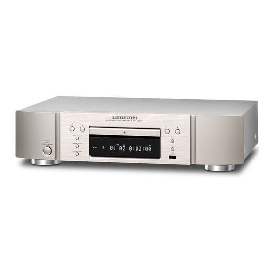
BLU-RAY DISC PLAYER
UD5007
UD5007 /
N1SG/N1B
U1B/K1B/S1B
SUPER AUDIO CD/
MODIFICATION NOTICE.
Ver. 7
Please refer to the
Advertisement
Table of Contents

Related Manuals for Marantz UD5007/N1SG


Summary of Contents for Marantz UD5007/N1SG
- Page 1 Service UD5007 / N1SG/N1B U1B/K1B/S1B Manual SUPER AUDIO CD/ BLU-RAY DISC PLAYER • For purposes of improvement, specifications and design are subject to change without notice. • Please use this service manual with referring to the operating instructions without fail. • Some illustrations using in this service manual are slightly different from the actual set. Ver.
-
Page 2: Table Of Contents
CONTENTS SAFETY PRECAUTIONS ............4 TROUBLE SHOOTING ............33 1. Power (Power Board) ............33 NOTE FOR SCHEMATIC DIAGRAM .........5 2. LED blinking ................34 NOTE FOR PARTS LIST ............5 3. Power board ................34 WARNING AND LASER SAFETY INSTRUCTIONS ....6 4. DISPLAY (Display Board) ............35 INSTRUCTIONS FOR HANDLING SEMI-CONDUCTORS 5. - Page 3 MARANTZ DESIGN AND SERVICE marantz Using superior design and selected high grade components, company has created the ultimate in stereo sound. marantz marantz Only original parts can insure that your product will continue to perform to the specifications for which it is famous.
-
Page 4: Safety Precautions
SAFETY PRECAUTIONS The following items should be checked for continued protection of the customer and the service technician. LEAKAGE CURRENT CHECK Before returning the set to the customer, be sure to carry out either (1) a leakage current check or (2) a line to chassis resistance check. -
Page 5: Note For Schematic Diagram
NOTE FOR SCHEMATIC DIAGRAM WARNING: Parts marked with this symbol z have critical characteristics. Use ONLY replacement parts recommended by the manufacturer. CAUTION: Before returning the unit to the customer, make sure you make either (1) a leakage current check or (2) a line to chassis resistance check. If the leakage current exceeds 0.5 milliamps, or if the resistance from chassis to either side of the power cord is less than 460 kohms, the unit is defective. -
Page 6: Warning And Laser Safety Instructions
WARNING AND LASER SAFETY INSTRUCTIONS WARNING AND LASER SAFETY INSTRUCTIONS WARNING WAARSCHUWING Alle IC’s en vele andere halfgeleiders zijn gevoelig All ICs and many other semi-conductors are voor elektrostatische ontladingen (ESD). susceptible to electrostatic discharges (ESD). Onzorgvuldig behandelen tijdens reparatie kan de Careless handling during repair can reduce life levensduur drastisch doen verminderen. -
Page 7: Instructions For Handling Semi-Conductors And Optical Unit
INSTRUCTIONS FOR HANDLING SEMI-CONDUCTORS AND OPTICAL UNIT Electrostatic breakdown of the semi-conductors or optical pickup may occur due to a potential difference caused by electrostatic charge during unpacking or repair work. 1. Ground for Human Body Be sure to wear a grounding band (1 MΩ) that is properly grounded to remove any static electricity that may be charged on the body. 2. -
Page 8: Technical Specifications
TECHNICAL SPECIFICATIONS n Performance Audio output characteristics : (1) Frequency response Signal format : NTSC, PAL Applicable discs /memory device : q BD (Linear PCM) : 2Hz ~ 22kHz (48kHz sampling) (1) BD-Video disc : : 2Hz ~ 44kHz (96kHz sampling) : 2Hz ~ 88kHz (192kHz sampling) 12 cm, 1 side, 1 layer;... -
Page 9: Cautions In Servicing
Refer to "MEASURING METHOD AND WAVEFORMS". When you repair the BD MECHA UNIT, you can use the following JIG. Please order to Marantz Official Service Distributor in your region if necessary. Do not supply it : 232C (TTL) – USB conversion jig (Model: DUT-06635 by GeeeTech) : 1 Set Part No. -
Page 10: Disassembly
DISASSEMBLY • Disassemble in order of the arrow in the following figure. • In the case of the re-assembling, assemble it in order of the reverse of the following flow. • In the case of the re-assembling, observe "attention of assembling". •... -
Page 11: Front Panel Assy
1. FRONT PANEL ASSY Proceeding : TOP COVER → LOADER PANEL FRONT PANEL ASSY → (1) Detach the LOADER PANEL. Shooting direction: B Pressed in metal rod having a mechanism for emergency open, stretched out like a small hole on the left side of the clip to. (2) Disconnect the connector wire and FFC. -
Page 12: Bd Mecha Unit Assy
2. BD MECHA UNIT ASSY Proceeding : TOP COVER MECHA COVER BD MECHA UNIT ASSY → → ※ Please ensure ESD protection prior to handling the BD MECHA. (1) Remove the screws. Screw of Mecha cover ×4 (2) Remove the screws. Screw of BD's Mecha ×4 (3) Disconnect the connector wire and FFC. -
Page 13: Main Pcb Unit Assy
3. MAIN PCB UNIT ASSY Proceeding : TOP COVER MAIN PCB UNIT ASSY → (1) Remove the screws. Remove the screws from REAR PANEL ×2 Remove the screws from TOP PANEL ×4 (2) Disconnect the connector wire and FFC. Disconnect 13P-FFC【XP8】, 12P-PH【XP1】 【XP4】... -
Page 14: Power Pcb Unit Assy
4. POWER PCB UNIT ASSY Proceeding : TOP COVER POWER PCB UNIT ASSY → (1) Remove the screws. Remove the screws from TOP ×5 (2) Disconnect the connector wire and FFC. Disconnect 12P-PH【CN502/503】, 3P-VH【CN501】 【CN502/503】 5. IR PCB UNIT ASSY Proceeding : TOP COVER IR PCB UNIT ASSY →... -
Page 15: Removing Discs
REMOVING DISCS (1) Remove the Top Cover. (2) Open the CD tray. Pressed in metal rod having a mechanism for emergency open, stretched out like a small hole on the left side of the clip to. Shooting direction: D... -
Page 16: Diagnostics Of Optical Pickup
DIAGNOSTICS OF OPTICAL PICKUP Make failure diagnostics of the Optical Pickup as follows. q If the laser drive current (Iop) becomes more than BD : ± 6 [mA], DVD or CD : ±12 [mA] of the initial value, the Optical Pickup should be replaced. -
Page 17: Iop Checked Method
1. Iop checked Method Select the laser ON/OFF(CD/DVD/BD)mode of the test mode, and check the Iop value of CD laser, DVD laser or BD laser. (Refer to "6. Test mode") FL Display (The display part of 13 digits) L a s e r O n O f f Laser current check Press the "... -
Page 18: How To Replace The Main Pcb & Bd Mecha Or Bd Mecha
HOW TO REPLACE THE MAIN PCB & BD MECHA OR BD MECHA NOTE: The optical pick-up laser diode (LD) is instantly degraded or damaged by static electricity or a power surge. When handling the BD MECHA UNIT, always be sure to earth yourself, and use an earth mat on the workbench and floor for grounding. - Page 19 [Connection] (1) Connect the 232C (TTL) side 4P PH connector of the USB - 232C (TTL) conversion jig to the MAIN PCB of the set. (2) Connect the USB side of the USB - 232C (TTL) conversion jig to the PC. 4P RE-PH CONN CORD (1000mm) USB - 232C(TTL) conversion jig MAIN PCB...
- Page 20 On the screen below, select "ComPort XX". Select the USB - 232C (TTL) conversion jig port. Enter the Bar Code BOX 32-digit hexadecimal number listed at the bottom of one-dimensional bar code replacement for the BD MECHA. One dimension of bar code data can stick to reading, Bar Code BOX in bar code leaders and can input. NOTE: The bar code data of the optical pickup, please do not enter the wrong data.
- Page 21 Click Write(F2). When “Pass” changes to green, writing to the Flash ROM of the MAIN PCB is complete. Switch off the set unit power, and remove the 232C (TTL) side 4P PH connector of the USB - 232C (TTL) conversion jig from the MAIN PCB (CON1).
- Page 22 2.4. Replace the BD MECHA UNIT ASSY (1) Remove the MECHA COVER. MECHA COVER (2) Move the optical pickup to the outer circumference, remove the FFC, and remove the screws. J2 45P-FFC J4 9P-FFC 5P-PH CORD BD MECHA (3) Attach the BD MECHA for replacement to the set unit. (When assembling the unit, perform the steps in reverse order.) (4) Check that the 45P-FFC, 9P-FFC and 5P-PH connector cords have been connected.
-
Page 23: How To Replace The Main Pcb Unit Assy
HOW TO REPLACE THE MAIN PCB UNIT ASSY s ・Service Part for the MAIN PCB UNIT ASSY MAIN PCB: (Part No. :919639100340M) 1.1. Devices Used (1) PC (2) USB - 232C (TTL) conversion jig (Model: DUT-06635 by GeeeTech) (Do not supply) (3) 4P RE-PH CONN CORD (1000mm) (Part No. - Page 24 1.6. Operation check (1) Connect the 45P FFC of J2 J2 45P FFC (2) Attach the MECHA COVER. (3) Attach the TOP COVER. (4) Follow the firmware update procedure, and update the firmware to the latest version. (see "VERSION UPGRADE PROCEDURE OF FIRMWARE") (5) Check the laser amperage (see laser on/off mode in the test mode (page 28)).
-
Page 25: Service Mode
Front-end and Back-end and SYS com version check mode. Press the "SETUP" button on the remote controller to display the SETUP menu. Press remote controller "3265". The version is displayed on the TV screen as follows. marantz General Setting Version HQ 0000xxxx... -
Page 26: Tray Lock Mode
3. Tray lock mode 3.1. preparation Equipment used: None Unit setting: No spec other than the following procedure. 3.2. procedure [Setting] Pressing the " 1 " and " 8 " buttons for simultaneously, plug the AC cord into a power outlet. "TRAY LOCK"... -
Page 27: Test Mode
6. Test mode 6.1. Entering the test mode The test mode is entered by pressing the " 5 " and " 8 " buttons simultaneously, plug the AC cord into a power outlet. When the test mode is set, the " 1 " and " 3 " indicators light. FL tube display when test mode entered FL Display (The display part of 13 digits) When the test mode is set, the choice screen of the mode appears on the monitor. - Page 28 6.3. About each mode ・ With the mode selected, press the " 1 " button to set that mode. (1) Laser on/off (CD/DVD/BD) mode Press the " 8 " or " 9 " button to select [X] and press the " 1 " button to set it. Laser on/off control is executed and the laser current is displayed.
- Page 29 (3) Accumulated laser on time display mode Press the " 8 " or " 9 " button to select [Y] and press the " 1 " button to set it. The accumulated laser on time is displayed. FL Display (The display part of 13 digits) (Y=1 : CD, 2 : DVD , 3 : BD, mmmmmm : Time(Fractions of hours are counted up one hour on the display.) When the "...
- Page 30 6.4. Stopping the mode When the " 2 " button is pressed, the layer above the current layer is displayed. The relationship between the different modes and the display of the different layers is shown on the table below. Mode 1 layer 2 layer 3 layer...
- Page 31 Error rate display details for each media type Measurement Remarks position The inner It is invalid. It is invalid. It is invalid. When this is selected for BD, DVD or circumference of CD, T84 FFFFFFFFFF display. 2-layer The inner LDC error detection PI error detection It is invalid.
-
Page 32: Procedure Firmware For Upgrading The Version Of The Firmware
PROCEDURE FIRMWARE FOR UPGRADING THE VERSION OF THE FIRMWARE You can update by downloading the latest version from the Internet. 1. Update from the Internet 1.1. preparation (1) System requirements • Internet Connection by Broadband Circuit • Modem • Router •... -
Page 33: Trouble Shooting
TROUBLE SHOOTING 1. Power (Power Board) 1. Power does not turn on. Power does not turn on. POWER_LED is not blinking red. Refer to "2. LED blinking". Check abnormalities of the circuit of a primary side. (Such as D501,D502,D503,D504,Ce501,Q501,U501) Is the fuse of F501 normal? Defect parts should be exchanged. -
Page 34: Led Blinking
2. LED blinking POWER_LED is blinking red. Check abnormalities of the connection circuit of +5V. PC0N (CN502#2) and +5V (CN502#3) are measured (Such as Q512,Q505) simultaneously. Defect parts should be exchanged. Before PCON is set to "L", +5V has not carried out When there are no abnormalities in a POWER board, voltage drops. -
Page 35: Display (Display Board)
4. DISPLAY (Display Board) FL TUBE doesn't light. Does not appear when press the "DIMMER" on the May be DIMMER was working. remote control. Also, May be "PURE DIRECT" was working. To replace the parts to check there is nothing wrong CHeck VFD_RST(U2#9). -
Page 36: Hdmi
5. HDMI No picture or sound is output. Is the set in "PURE DIRECT MODE" "Off"? Set the "PURE DIRECT MODE" "Off". Is a contact part of HDMI JACK J1 normal? Is there no damage around the contact where HDMI Replace the HDMI JACK. -
Page 37: Usb
7. USB Does not recognize the USB. Is there nothing wrong with the USB connector P1 of the Display PCB? Is there no damage around the contact where USB Replace the F.PANEL ASSY cable are inserted. Are there no bad solder joints? Is there is nothing wrong with the 4P cable JP1 of Display PCB? Replace the F.PANEL ASSY... -
Page 38: Disc Playback Error
9. Disc playback error Disc playback error Is 45P FFC inserted properly to J2 of Main PCB? 45P FFC inserted into the J2. Is 9P FFC inserted properly to J4 of Main PCB? 9P FFC inserted into J4. Is 5P PH connector inserted properly to X10 of Main 5P PH connector to be inserted into theX10. -
Page 39: Block Diagram
BLOCK DIAGRAM HDMI Ethernet HDMI_5V FOR UD5007 +5V_STBY NJM2882 PESD_TPD4S010B IR SWITCH BOARD +12VA LFE8634 Audio AMP&LPF NJM4565 -12V HDMI OUTPUT 100-240V 50/60Hz AUDIO_5V AUDIO DAC POWER AC IN PM1781 MCU_3.3V G9091-330T11U CS8966 MT8555/DPBG EEPROM NCP1271 POWER_K POWER 3.3V 3.3V 3.3V LDO SUPPLY 1Gbit... -
Page 40: Power Block Diagram
POWER BLOCK DIAGRAM +12VM PCON +12VA -12VA (U512) L79L12ACZ (U501) PCON NCP1271 +5VSTB MAIN BOARD +5V(VCC PCON (U503) TL431 PCON STANDBY ON/OFF... -
Page 41: Printed Wiring Boards
PRINTED WIRING BOARDS MAIN MAIN (COMPONENT SIDE) (FOIL SIDE) 鉛フリー半田 半田付けには、鉛フリー半田 (Sn-Ag-Cu) を使用してください。 Lead-free Solder When soldering, use the Lead-free Solder (Sn-Ag-Cu). -
Page 42: Front
FRONT (COMPONENT SIDE) PWD1G (COMPONENT SIDE) 鉛フリー半田 半田付けには、鉛フリー半田 (Sn-Ag-Cu) を使用してください。 Lead-free Solder When soldering, use the Lead-free Solder (Sn-Ag-Cu). -
Page 43: Front
FRONT (FOIL SIDE) PWDG1 (FOIL SIDE) 鉛フリー半田 半田付けには、鉛フリー半田 (Sn-Ag-Cu) を使用してください。 Lead-free Solder When soldering, use the Lead-free Solder (Sn-Ag-Cu). -
Page 44: Ira1G
IRA1G IRA1G (COMPONENT SIDE) (FOIL SIDE) USE1G USE1G (COMPONENT SIDE) (FOIL SIDE) 鉛フリー半田 半田付けには、鉛フリー半田 (Sn-Ag-Cu) を使用してください。 Lead-free Solder When soldering, use the Lead-free Solder (Sn-Ag-Cu). -
Page 45: Schematic Diagrams (1/15)
L552 L552 3.3uH/3A 3.3uH/3A +12VA +12VA/0.1A R572 R572 CE560 CE560 C559 C559 0.1uF/50V/X7R 0.1uF/50V/X7R 470uF/16V 470uF/16V JP507 JP507 CY505 CY505 CY504 CY504 470pF/250VAC 470pF/250VAC C503 C503 C502 C502 CY503 CY503 Q507 Q507 P_AP6679GI P_AP6679GI 0.0022uF(222)400V 0.0022uF(222)400V 470pF/250VAC 470pF/250VAC +M12V L551 L551 3.3uH/3A 3.3uH/3A... -
Page 46: Display_01
18P_ FFC_1.0mm 18P_ FFC_1.0mm +5V_STBY +5V_STBY KEY_IN_A VFD_RST1 3.3V 3.3V KEY_IN_A IR_IN KEY_IN_B KEY_IN_B W_REMOTE STANDBY_KEY IR_IN IR_IN STANDBY_KEY VDATA IR_IN VCLK VSTB +5V_STBY IRM_12mm IRM_12mm 0.1uF/50V/Y5V/NC 0.1uF/50V/Y5V/NC 10K/NC 10K/NC +12V 3.3V DTA114EUA DTA114EUA STANDBY_KEY W_REMOTE KEY_IN_A KEY_IN_B IR TX module MCU_LED_CTRL_1 +5V_STBY MCU_LED_CTRL_2... -
Page 47: Display_02
KEY_IN_A KEY_IN_A KEY_IN_B KEY_IN_B STANDBY_KEY STANDBY_KEY Marantz KEY_IN_A KEY_IN_B STANDBY_KEY C204 C204 ESD4 ESD4 R113 R113 C205 C205 R119 R119 R114 R114 ESD5 ESD5 ESD3 ESD3 C206 C206 0.01uF/50V/Y5V 0.01uF/50V/Y5V 0/1% 0/1% 15K/1% 15K/1% 39K/1% 39K/1% 2.49k/1% 2.49k/1% 6.8K/1% 6.8K/1% 0.01uF/50V/Y5V... - Page 48 +5V_STBY BZX79C6V2 BZX79C6V2 FB15 FB15 C407 C407 0.01uF/50V/Y5V 0.01uF/50V/Y5V +5V_NSW_232C C404 C404 C406 C406 BAV16W BAV16W 1000pF/50V/X7R 1000pF/50V/X7R KRA104S KRA104S BAV16W BAV16W 3.3K 3.3K C403 C403 220pF/50V/NP0 220pF/50V/NP0 W_REMOTE FB11 FB11 KTC3875S KTC3875S C402 C402 SOT-23 SOT-23 C405 C405 C398 C398 C399 C399...
-
Page 49: Main_01
+12V +12V_D 100pF/50V/NP0 100pF/50V/NP0 100pF/50V/NP0 100pF/50V/NP0 +5V_STBY +5V_STBY PS_ON# PS_ON# 100pF/50V/NP0 100pF/50V/NP0 100pF/50V/NP0 100pF/50V/NP0 POWER BOARD 10/2A 10/2A +5V_STBY PS_ON# 10/2A 10/2A 1.1V0 1.15V 10/2A 10/2A 0.1uF/25V/Y5V 0.1uF/25V/Y5V VCC_D POWER VCC1 VCC1 1.2K/1% 1.2K/1% 10/2A 10/2A 0.1uF/25V/Y5V 0.1uF/25V/Y5V 10uF/10V/Y5V 10uF/10V/Y5V +12V 500/800mA 500/800mA... -
Page 50: Main_02
1.2V 1.5V AVDD12_MEMPLL A_DQ3 A_RA0 A_DQ18 A_RA0_2R AA25 A_DQ7 A_RA1 A_DQ23 A_RA1_2R DVCC18_IO_1 AE10 A_DQ19 A_RA2_2R A_DQ1 A_RA2 DVCC18_IO_1 AF14 A_DQ6 A_RA3 A_DQ21 A_RA3_2R DVCC18_IO_1 AE17 AG17 A_DQ0 A_DQ0 A_RA4 A_DQ16 A_RA4_2R DVCC18_IO_1 RDQ0 0.1uF/16V/Y5V 0.1uF/16V/Y5V AF20 AF18 A_DQ1 A_DQ5 A_RA5 A_DQ20 A_RA5_2R... -
Page 51: Main_03
1.1V B_DQ0 1.1V 1.1V DVCC10_K RDQ0_B B_DQ1 DVCC10_K RDQ1_B B_DQ2 DVCC10_K RDQ2_B B_DQ3 B_DQ1 B_RA0 B_DQ19 B_RA0_2R DVCC10_K RDQ3_B B_DQ4 B_DQ6 B_RA1 B_DQ23 B_RA1_2R DVCC10_K RDQ4_B B_DQ5 B_DQ0 B_RA2 B_DQ16 B_RA2_2R DVCC10_K RDQ5_B B_DQ6 B_DQ7 B_RA3 B_DQ21 B_RA3_2R DVCC10_K RDQ6_B B_DQ7 B_DQ3 B_RA4... -
Page 52: Main_04
3.3V Analog Power AVDD33_VDAC_R AOMCLK_ R335 R335 AVDD33_VDAC_R AOMCLK AOMCLK AOBCK_ R336 R336 HDMI Port HDMI TX AOBCK AVSS33_VDAC_R AOBCK AOLRCK_ R337 R337 AOLRCK AOLRCK AVDD33_VDAC_X AOSDATA0_ R338 R338 3.3V AVDD33_VDAC_X AOSDATA0 AOSDATA0 AOSDATA1_ R339 R339 AOSDATA1 TP48 TP48 AVSS33_VDAC_X AOSDATA1 Differential Signal ! AOSDATA2_... -
Page 53: Main_05
3.3V_N NAND Flash 3.3V 3.3V_N R160 R160 3.3V_N 3.3V_N DVCC33_IO_5 STXN DVCC33_IO_5 STXP NAND 8Gbits NAND 8Gbits CL21 CL21 DVCC33_IO_2 NFM18PS/NC NFM18PS/NC DVCC33_IO_2 SRXP DVCC33_IO_3 SRXN C134 C134 C135 C135 DVCC33_IO_3 0.1uF/16V/X7R 0.1uF/16V/X7R 4.7uF/10V/Y5V 4.7uF/10V/Y5V DVCC33_IO SREXT R101 R101 453_1% 453_1% 8PIN/1.0mm 8PIN/1.0mm... -
Page 54: Main_06
TO VFD BOARD 3.3V LCDRD R132 VFD_RST IR_IN R310 R310 DVCC33_IO_STB W_REMOTE DVCC33_IO_STB GPIO8 VDATA VDATA_1 R135 DVCC33_IO_STB VCLK R133 VCLK_1 ETCOL CL32 CL32 VSTB R134 VSTB_1 ETCRS NFM18PS/NC NFM18PS/NC ETMDC +5V_STBY ETMDIO ETRXCLK +12V ETRXD0 ETRXD1 3.3V STANDBY_KEY ETRXD2 KEY_IN_A ETRXD3 AVDD33_LDO... -
Page 55: Main_07
MCU_AMUTE MCU_AMUTE MIX_OP+12V AOMCLK AOMCLK AOBCK AOBCK MBRX130/30V/1A MBRX130/30V/1A +5V_STBY AOLRCK MIX_OP+12V AOLRCK 78L05 78L05 AOSDATA0 AOSDATA0 MBRX130/30V/1A MBRX130/30V/1A +12VA MIX_+5V_DAC -12VA MIX_OP-12V +12VA R146 R146 500/800mA/NC 500/800mA/NC -12VA C199 C199 C198 C198 FB10 FB10 500/800mA/NC 500/800mA/NC 0.1uF/50V/X7R 0.1uF/50V/X7R 100uF/25V/RFO 100uF/25V/RFO C200 C200... -
Page 56: Main_08
1.2V 600/500mA 600/500mA FB22 FB22 AVDD12_HDMI_RX VDD12_HDMI_RX VDINHSYNC VDD12_HDMI_RX VDINVSYNC VDINCLK C218 C218 C219 C219 0.1uF/16V/X7R 0.1uF/16V/X7R LED_B1 LED_B1 VDIN0 VSS33_HDMI_RX VDIN1 LED_A1 LED_A1 VSS33_HDMI_RX VDIN2 VDIN3 R195 R195 VDIN3 VDIN4 3.3V VDIN5 VDIN6 FB23 FB23 600/500mA 600/500mA AVDD33_HDMI_RX VDD33_HDMI_RX VDIN7 VDD33_HDMI_RX VDIN8... -
Page 57: Main_09
A3.3V RSTI RSTI1 RSTI1 TP39 TP39 TP40 TP40 R197 R197 TP41 TP41 FE RS232 Port TP42 TP42 A1.2V TP43 TP43 FE_GND C222 C222 3.3V TP44 TP44 0 OHM 0 OHM 47K/NC 47K/NC 4.7uF/16V/Y5V 4.7uF/16V/Y5V RFO- RFO-1 RFO-1 1206-R 1206-R URXD RFO+ RFO+1 RFO+1... -
Page 58: Main_10
MOTOR DRIVER TI2050G4 M12V_T Separate this +12V trace and MVCC_T +12V_D other +12V element(audio TPIC_TR+ TR+ 10 M12V_T buffer,VCC_BD_LD) from the U703 U703 TPIC_TR- TR- 10 power source connector. WSD521S WSD521S TPIC_B+ R713 R713 TPIC_FR+ SLED1_P P5V_2 FR+ 10 TPIC_B- R714 R714 TPIC_CO_A-... -
Page 59: Main_11
MCU CS8966F GPIO LIST MCU_3.3V MCU_2.5V RESET Circuit MT8555_PS_ON# : H--->MCU UPGRADING MODE MCU_3.3V NAME FEATURES AND NET MCU_3.3V C290 C290 R248 R248 L--->MCU NORMEAL MODE P3.7 R249 R249 0.1uF/50V/Y5V 0.1uF/50V/Y5V 4.7K 4.7K R250 R250 LL4148 LL4148 MT8555_PS_ON# MT8555_PS_ON# R252 R252 HDMI_POWER_CTRL R251... -
Page 60: Exploded View
EXPLODED VIEW WARNING: Parts marked with this symbol have critical characteristics. Use ONLY replacement parts recommended by the manufacturer. 印の部分は安全を維持するために重要 な部品です。従って交換時は必ず指定の 部品を使用してください。... -
Page 61: Parts List Of Exploded View
Q'ty New 919402102030M FRONT PANEL ASSY (5007) BK 08-UD50F1-000 919402102040M FRONT PANEL ASSY (5007) SG 08-UD50F1-001 WINDOW ESC DAMPER FRONT PANEL FUNCTION KNOB(4P) MARANTZ BADGE POWER KNOB POWER LENS FUNCTION KNOB(5P) LENS 919418100370M LOADER PANEL 55-UD50D1-0HAB1 919418100380M LOADER PANEL 55-UD50D1-0HAB3... - Page 62 Ref.No. Part No. Part Name Remarks Q'ty New ACETATE TAPE ACETATE TAPE SCREWS M3X8 CBTS(B) M3X6 CBTS(B)-B M2.6X6 CBTS(P) M3X6 CBTS(B)-B No.17 same M3X8 CBTS(B)-B No.30 same M3X8 CBTS(B)-B M3X6 CBTS(B) M3X6 CBTS(S) M3X6 CBTS(S) M3X6 CBTS(S) No.42 same WIRES 4P PH-PH CORD ★...
-
Page 63: Packing View
PACKING VIEW 9 10... -
Page 64: Parts List Of Packing View
PARTS LIST OF PACKING VIEW zParts indicated by "nsp" on this table cannot be supplied. zParts indicated by the " ★ " mark are not illustrated in the packing view. zThe parts listed below are only for maintenance, might differ from the parts used in the unit in appearances or dimensions. NOTE: The symbols in the column "Remarks"... -
Page 65: Semiconductors
SEMICONDUCTORS Only major semiconductors are shown, general semiconductors etc. are omitted to list. The semiconductor which described a detailed drawing in a schematic diagram are omitted to list. 1. IC's PCM1781 (U15) DEVICE INFORMATION PIN ASSIGNMENTS PCM1781 (TOP VIEW) ZEROA DEMP0 DEMP1 MUTE... - Page 66 CS8966 (U23) VDD25 P1.2 / SDA / SWC0 P1.3 / SCL / SWC1 RSTN P1.4 / SWC2 P2.4 / T2EX / CMPD P1.5 / SWC3 P2.5 / T2 / CMPC P1.6 / T1 / SWB1 / PINT0.0 CS8966F P2.6 / CMPB P1.7 / T0 / SWB0 / PINT0.1 PQFP-44 P2.7 / CMPA / SWA0...
- Page 67 PIN DESCRIPTION FUNCTION DESCRIPTION Port 3.7 GPIO 8051 P3.7 GPIO. SPICLK P3.7 I/O, A It behaves as the Master clock output (Master Mode), or Slave clock input (Slave Mode) of the on-chip SPI interface. PGAVMID PGA VMID output. Port 3.6 GPIO 8051 P3.6 GPIO.
- Page 68 FUNCTION DESCRIPTION Port 4.1 GPIO 8051 P4.1 GPIO. P4.1 I/O, A SDA2 This pin also can be configured as the SDA signal of the 2 I2C slave controller. In this operation mode, this pin should also be configured as bi-directional I/O with open- drain output.
- Page 69 CS8966 Preliminary FUNCTION DESCRIPTION Port 1.7 GPIO 8051 P1.7 GPIO. PINT0.1 This pin also can be configured as the expanded INT0 interrupt. P1.7 I/O, A T0 Timer 0 Input This pin also can be configured as Timer 0 input. SWB0 This pin also serves as one of the connection for analog switch B.
- Page 70 FUNCTION DESCRIPTION Port 4.5 GPIO 8051 P4.5 GPIO. P4.5 I/O, A SWC5 This pin also serves as one of the connection for analog switch C. The control of the analog switch is done by setting of ANEN of IOCFGP4.5. Port 1.1 GPIO 8051 P1.1 GPIO.
- Page 71 FUNCTION DESCRIPTION Port 0.4 GPIO 8051 P0.4 GPIO. PINT1.4 P0.4 I/O, A This pin also can be configured as the expanded INT1 interrupt. ADC1 This pin also can be configured as the input to the ADC channel C by setting ANEN of IOCFGP0.4 to 1.
- Page 72 FUNCTION DESCRIPTION Reset Low Active. Typically connect a resistor to VDD25 and a capacitor to VSS. RSTN Low asserted and threshold at 0.5*VDD25. When forced low, the chip enters into reset condition. This pin should not be connected to any level above VDD25. Port 4.6 GPIO 8051 P4.6 GPIO.
- Page 73 FUNCTION DESCRIPTION Port 3.1 GPIO 8051 P3.1 GPIO. CEX3 PCA CCAP Module 3 This pin also can be configured as CEX pin for PCA CCP module 3. CEX is an I/O P3.1 I/O, A interface signal for compare/capture input and PWM output. SWA2 This pin also serves as one of the connection for analog switch A.
- Page 74 TPIC2050 (U703) Terminal Assignments SLED1_P P5V_2 SLED1_N STP2_N P12V_3 STP2_P STP1_N SLED2_P STP1_P SLED2_N AGND PGND_2 C10V ISENSE MCOM ICOM2 GPOUT P12V_2 ICOM1 SCLK P12V_1 SIMO PGND_1 SOMI FCS_N SIOV FCS_P XRSTIN TRK_N PULL_CTL TRK_P VLDDIN TLT_P CV3P3 TLT_N AGND/DGND P5V_1 A9P5V ILDD_BD...
- Page 75 1.3. Signal description List 1 Signal description Name description SLED1_P Sled1 positive output terminal SLED1_N Sled1 negative output terminal P12V_3 Power supply terminal for 12V drivers output SLED2_P Sled2 positive output terminal SLED2_N Sled2 negative output terminal PGND_2 GND terminal for 12V drivers C10V MISC The capacitance connection terminal for internal regulator.
- Page 76 MCOM Motor center tap connection ISENSE Current sense input terminal for spindle drivers AGND Ground terminal for internal analog STP1_P STP1 positive output terminal for collimator STP1_N STP1 negative output terminal for collimator STP2_P STP2 positive output terminal for collimator STP2_N STP2 negative output terminal for collimator P5V_2...
-
Page 77: Parts List Of Pcb
PARTS LIST OF PCB zParts indicated by "nsp" on this table cannot be supplied. zPCB ASS'Y indicated by "nsp" on this table cannot be supplied. When repairing the PCB ASS'Y, check the board parts list and order replacement parts. zThe parts listed below are only for maintenance, might differ from the parts used in the unit in appearances or dimensions. Ref.No. - Page 78 Ref.No. Part No. Part Name Remarks Q'ty New Q512 919222500230D (-30V/-14.9A)PMK35EP 12-PMK35E-0BX Q508 90M-HX600040R NPN TRANSISTOR 3CG3906M SOT-23 12-BT3906-0BX Q505,506 90M-HX600030R NPN TRANSISTOR 3DG3904M SOT-23 12-BT3904-0BX Q509,510 90M-HX600030R NPN TRANSISTOR 3DG3904M SOT-23 12-BT3904-0BX Q501 919222500240D MOSFET SMK0460F TO-220F 11-MK0465-0CX Q511 919214500260D NPN TRANSISTOR MMBT8050C SOT-23 12-BT8050-CBX...
Need help?
Do you have a question about the UD5007/N1SG and is the answer not in the manual?
Questions and answers