Endress+Hauser iTEMP TMT82 Operating Instructions Manual
Hide thumbs
Also See for iTEMP TMT82:
- Operating instructions manual (114 pages) ,
- Safety instructions (28 pages) ,
- Brief operating instructions (28 pages)

Related Manuals for Endress+Hauser iTEMP TMT82


Summary of Contents for Endress+Hauser iTEMP TMT82
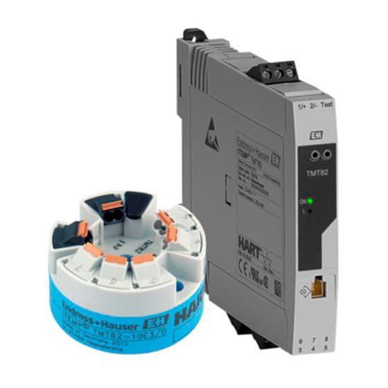
- Page 1 Products Solutions Services BA01028T/09/EN/26.24-00 71662730 2024-04-15 Valid as of version 01.02 (device version) Operating Instructions iTEMP TMT82 2-channel temperature transmitter with HART ® protocol...
-
Page 3: Table Of Contents
TMT82 Table of contents Table of contents About this document ....4 Commissioning ....38 Document function . -
Page 4: About This Document
About this document iTEMP TMT82 About this document Document function These Operating Instructions contain all the information required in the various life cycle phases of the device: from product identification, incoming acceptance and storage, to installation, connection, operation and commissioning, through to troubleshooting, maintenance and disposal. -
Page 5: Tool Symbols
For an overview of the scope of the associated Technical Documentation, refer to the following: • Device Viewer (www.endress.com/deviceviewer): Enter the serial number from the nameplate • Endress+Hauser Operations app: Enter serial number from nameplate or scan matrix code on nameplate. Endress+Hauser... -
Page 6: Registered Trademarks
About this document iTEMP TMT82 The following documentation may be available depending on the device version ordered: Document type Purpose and content of the document Technical Information (TI) Planning aid for your device The document contains all the technical data on the device and provides an overview of the accessories and other products that can be ordered for the device. -
Page 7: Basic Safety Instructions
TMT82 Basic safety instructions Basic safety instructions Requirements for the personnel The personnel for installation, commissioning, diagnostics and maintenance must fulfill the following requirements: ‣ Trained, qualified specialists must have a relevant qualification for this specific function and task. -
Page 8: Product Safety
Incoming acceptance and product identification iTEMP TMT82 Modifications to the device Unauthorized modifications to the device are not permitted and can lead to unforeseeable dangers! ‣ If modifications are nevertheless required, consult with the manufacturer. Repair To ensure continued operational safety and reliability: ‣... -
Page 9: Product Identification
(www.endress.com/deviceviewer): all the information about the device and an overview of the Technical Documentation supplied with the device are displayed. • Enter the serial number from the nameplate into the Endress+Hauser Operations App or scan the 2-D matrix code (QR code) on the nameplate with the Endress+Hauser Operations App: all the information about the device and the technical documentation pertaining to the device is displayed. - Page 10 Incoming acceptance and product identification iTEMP TMT82 Maximum relative humidity: < 95 % as per IEC 60068-2-30 Pack the device for storage and transportation in such a way that it is reliably protected against impact and external influences. The original packaging offers the best protection.
-
Page 11: Mounting
TMT82 Mounting Mounting Mounting requirements 4.1.1 Dimensions The dimensions of the device are provided in the "Technical data" section→ 49. 4.1.2 Mounting location • Head transmitter: • In the terminal head, flat face, as per DIN EN 50446, direct mounting on insert with cable entry (middle hole 7 mm (0.28 in)) - Page 12 Mounting iTEMP TMT82 4.2.1 Mounting the head transmitter PZ 2 PZ 1 . 7 2 i n ) . 7 2 i n ) PZ 2 PZ 1 PZ 2 A0048718 1 Head transmitter mounting (three versions) Item A...
- Page 13 TMT82 Mounting Item B Mounting in a field housing Field housing cover Mounting screws with springs Head transmitter Field housing 21 mm (0.83 in) . 7 2 i n ) 6.5 mm (0.25 in) . 5 1 i n ) A0024604 ...
- Page 14 Mounting iTEMP TMT82 Remotely mounting the field mount housing (2.01) 25 (0.98) (6.3) (7.1) ≤ 50 (1.97) 72 (2.8) 10.5 (0.41) A0027188 3 Mounting the field mount housing using special mounting bracket, see chapter ' A ccessories' . Dimensions in mm (in) Combined wall/pipe mounting bracket 2", L-shaped, material 304...
- Page 15 The display can be used only with the appropriate terminal heads - cover with viewing window (e.g. TA30 from Endress+Hauser). In the field mount housing with separate terminal compartment the display is already installed. Endress+Hauser...
- Page 16 Mounting iTEMP TMT82 Display installation positions in the field mount housing with separate terminal compartment 90° 90° 3 mm A0042436 5 Display installation positions, attachable in 90° stages Marking on foam ring 1. Remove the cover clamp. 2. Unscrew the housing cover together with the O-ring.
-
Page 17: Post-Mounting Check
TMT82 Mounting A0017821 6 Mounting the DIN rail transmitter 1. Slide the upper DIN rail clip upwards and the lower clip downwards until they click into place. 2. Fit the device on the DIN rail from the front. -
Page 18: Electrical Connection
Electrical connection iTEMP TMT82 Electrical connection CAUTION ‣ Switch off the power supply before installing or connecting the device. Failure to observe this may result in the destruction of parts of the electronics. ‣ Do not occupy the display connection. An incorrect connection can destroy the electronics. -
Page 19: Quick Wiring Guide
TMT82 Electrical connection 3 mm A0042426 On completion of the wiring, tighten the screw terminals of the connections. Tighten the cable glands again. Refer to the information provided in the "Ensuring the degree of protection" section. Screw the housing cover tight again and fit the cover clamp back on. - Page 20 Electrical connection iTEMP TMT82 RD RD YE (WH) BK (RD) BK (RD) A0047534 8 Terminal assignment of the field mount housing with separate terminal compartment Sensor input 1, RTD, : 2-, 3- and 4-wire Sensor input 2, RTD: 2-, 3-wire...
-
Page 21: Connecting The Sensor
TMT82 Electrical connection 1/+ 2/- Test Test TMT82 (BK) (BK) (YE) A0047533 9 Assignment of terminal connections for DIN rail transmitter 4 to 20 mA power supply To check the output current, an ammeter (DC measurement) can be connected between the "Test" and "-" terminals. - Page 22 Electrical connection iTEMP TMT82 NOTICE When connecting 2 sensors ensure that there is no galvanic connection between the sensors (e.g. caused by sensor elements that are not isolated from the thermowell). The resulting equalizing currents distort the measurements considerably. ‣...
-
Page 23: Connecting The Transmitter
TMT82 Electrical connection Fig. B, fine-strand wire without ferrule: 1. Strip wire end. Minimum stripping length 10 mm (0.39 in). 2. Press down on the lever opener. 3. Insert the wire end into the terminal. 4. Release lever opener. -
Page 24: Ensuring The Degree Of Protection
Electrical connection iTEMP TMT82 A0014463 12 Shielding and grounding the signal cable at one end with HART communication Optional grounding of the field device, isolated from cable shielding Grounding of the cable shield at one end Supply unit Grounding point for HART communication cable shield Ensuring the degree of protection The device meets the requirements for IP67 protection. - Page 25 TMT82 Electrical connection Device condition and specifications Notes Does the supply voltage match the specifications on • Head transmitter: U = 11 to 42 V the nameplate? • DIN rail transmitter: U = 12 to 42 V • SIL mode: U = 11 to 32 V...
-
Page 26: Operation Options
Operation options iTEMP TMT82 Operation options Overview of operation options FieldCare RN22/ RN42 HART Modem TMT82 A0042440 14 Operation options for the transmitter via HART communication For the head transmitter, display and operating elements are available locally only if... -
Page 27: Structure And Function Of The Operating Menu
TMT82 Operation options Structure and function of the operating menu 6.2.1 Structure of the operating menu Operating menu for operators and maintenances Setup Device tag Unit Assign cur. outp. (PV) 4 mA-value 20 mA-value Sensor type Sensor offset Advanced setup... - Page 28 Operation options iTEMP TMT82 The configuration in the SIL mode is different from the configuration in the standard mode. For more detailed information, please refer to the Functional Safety Manual (FY01105T). Submenus and user roles Certain parts of the menu are assigned to certain user roles. Each user role corresponds to typical tasks within the life cycle of the device.
-
Page 29: Measured Value Display And Operating Elements
TMT82 Operation options Measured value display and operating elements 6.3.1 Display elements Head transmitter A0008549 15 Optional LC display for head transmitter Item no. Function Description Displays the TAG TAG, 32 characters long. "Communication" symbol The communication symbol appears when read and write-accessing via the fieldbus protocol. - Page 30 Operation options iTEMP TMT82 Two LEDs on the front indicate the device status. Type Function and characteristic Status LED (red) When the device is operating without errors, the device status is displayed. This function can no longer be guaranteed in the event of an error.
-
Page 31: Access To The Operating Menu Via The Operating Tool
By using the status information, it is also a simple but effective way of checking their status and condition. Access takes place via the HART protocol or CDI interface (= Endress+Hauser Common Data Interface). - Page 32 6.4.2 DeviceCare Function scope The fastest way to configure Endress+Hauser field devices is to use the dedicated DeviceCare tool. DeviceCare' s user-friendly design allows transparent and intuitive device connection and configuration. Intuitive menus and step-by-step instructions with status information ensure optimum transparency.
- Page 33 TMT82 Operation options User interface A0055534 6.4.3 Field Xpert Function scope Field Xpert is a tablet PC with integrated touchscreen for commissioning and maintaining field devices in explosion hazardous and safe areas. It enables the efficient configuration of FOUNDATION fieldbus, HART and WirelessHART devices. Communication is wireless via Bluetooth or WiFi interfaces.
- Page 34 Operation options iTEMP TMT82 6.4.6 SIMATIC PDM Function scope SIMATIC PDM is a standardized, manufacturer-independent program from Siemens for the operation, configuration, maintenance and diagnosis of intelligent field devices via HART protocol. Source for device description files See details. → 35 6.4.7...
-
Page 35: System Integration
TMT82 System integration System integration Version data for the device Firmware version 01.02.zz • On the title page of the Operating instructions • On the nameplate • Firmware version parameter Diagnosis → Instrument info → Firmware version Manufacturer ID... -
Page 36: Device Variables And Measured Values
System integration iTEMP TMT82 Device variables and measured values The following measured values are assigned to the individual device variables: Device variable code Measured value Sensor 1 Sensor 2 Device temperature Average of sensor 1 and sensor 2 Difference between sensor 1 and sensor 2... - Page 37 TMT82 System integration Command No. Designation 13, Cmd013 Read TAG, descriptor, date 14, Cmd014 Read primary variable transducer information 15, Cmd015 Read device information 16, Cmd016 Read final assembly number 17, Cmd017 Write message 18, Cmd018 Write TAG, descriptor, date...
-
Page 38: Commissioning
Commissioning iTEMP TMT82 Commissioning Function check Before commissioning the measuring point make sure that all final checks have been carried out: • "Post-mounting check" checklist, → 17 • "Post-connection check" checklist, → 24 Switch on the device Once you have completed the post-connection checks, switch on the supply voltage. The transmitter performs a number of internal test functions after power-up. -
Page 39: Diagnostics And Troubleshooting
. • If possible, test the display module Display is blank with other suitable head transmitters, e.g. an Endress+Hauser head transmitter. The display module is defective. Replace the module. The electronics of the head Replace the head transmitter. -
Page 40: Diagnostic Information Via Light Emitting Diodes
Diagnostics and troubleshooting iTEMP TMT82 Problem Possible cause Remedy The cable resistance of the sensor (2- Compensate the cable resistance. wire) was not compensated. Offset incorrectly set. Check offset. Sensor defective. Check the sensor. RTD connected incorrectly. Install the connecting cables correctly (terminal diagram). -
Page 41: Diagnostic Information On Local Display
TMT82 Diagnostics and troubleshooting Diagnostic information on local display A0014837 Display in the event of a warning Display in the event of an alarm Status signal in the header The display alternates between the primary measured value and the status - indicated by the appropriate letter (M, C or S) - plus the defined error number. -
Page 42: Diagnostic List
Diagnostics and troubleshooting iTEMP TMT82 Diagnostic event and event text The fault can be identified by means of the diagnostic event. The event text helps you by providing information about the fault. Diagnostic event Status signal Event number Event text ↓... - Page 43 TMT82 Diagnostics and troubleshooting Status signal Diagnosti from the Diagnostic factory Short text Corrective measure behavior number from the Can be factory changed Sensor connection 1. Check electronic wiring. Alarm 2. Replace sensor. 3. Check connection type. 4. Contact service.
-
Page 44: Software History And Overview Of Compatibility
Diagnostics and troubleshooting iTEMP TMT82 Status signal Diagnosti from the Diagnostic factory Short text Corrective measure behavior number from the Can be factory changed Linearization 1. Check configuration of sensor Alarm parameters. 2. Check configuration of special sensor linearization. 3. Contact service. -
Page 45: Maintenance And Cleaning
TMT82 Maintenance and cleaning Date Firmware version Modifications Documentation 01/11 01.00.zz Original firmware BA01028T/09/en/13.10 10/12 01.00.zz No changes to functions and operation. BA01028T/09/en/14.12 02/14 01.01.zz Functional safety (SIL3) BA01028T/09/en/15.13 02/17 01.01.zz Change in operating parameters for Functional Safety BA01028T/09/en/17.17 (SIL3) 04/19 01.02.zz... -
Page 46: Disposal
12.1 Device-specific accessories Accessories for the head transmitter TID10 display unit for Endress+Hauser head transmitter iTEMP TMT8x or TMT7x, attachable Field housing TA30x for Endress+Hauser head transmitter Adapter for DIN rail mounting, clip as per IEC 60715 (TH35) without securing screws... -
Page 47: Communication-Specific Accessories
• Automatic verification of exclusion criteria • Automatic creation of the order code and its breakdown in PDF or Excel output format • Ability to order directly in the Endress+Hauser Online Shop The Configurator is available on the Endress+Hauser website: www.endress.com... -
Page 48: System Components
Technical Information TI00028S Netilion IIoT ecosystem: Unlock knowledge With the Netilion IIoT ecosystem, Endress+Hauser enables you to optimize plant performance, digitize workflows, share knowledge, and enhance collaboration. Drawing on decades of experience in process automation, Endress+Hauser provides the process industry with an IIoT ecosystem that unlocks valuable insights from data. These insights allow process optimization, leading to increased plant availability, efficiency, and reliability - ultimately resulting in a more profitable plant. -
Page 49: Technical Data
TMT82 Technical data Technical data 13.1 Input Measured variable Temperature (temperature-linear transmission behavior), resistance and voltage. Measuring range It is possible to connect two sensors that are independent of one another . The measuring inputs are not galvanically isolated from each other. -
Page 50: Output
Technical data iTEMP TMT82 Min. Thermocouples as Description Measuring range limits measuring per standard span Recommended temperature range: Type A (W5Re-W20Re) (30) 0 to +2 500 °C (+32 to +4 532 °F) 0 to +2 500 °C (+32 to +4 532 °F) 50 K (90 °F) - Page 51 TMT82 Technical data Failure information Failure information as per NAMUR NE43: Failure information is created if the measuring information is missing or not valid. A complete list of all the errors occurring in the measuring system is created. Underranging Linear decrease from 4.0 to 3.8 mA...
-
Page 52: Power Supply
Technical data iTEMP TMT82 Switch-on delay • Until the start of HART communication, approx. 6 s , while switch-on delay = I ≤3.8 mA • Until the first valid measured value signal is present for HART communication and at the current output, approx. -
Page 53: Performance Characteristics
TMT82 Technical data 13.4 Performance characteristics Response time The measured value update depends on the type of sensor and connection method and moves within the following ranges: Resistance thermometers (RTD) 0.9 to 1.5 s (depends on the connection method 2/3/4-wire) Thermocouples (TC) 1.1 s... - Page 54 Technical data iTEMP TMT82 Standard Name Measuring range Measurement error (±) –185 to +1 100 °C Pt50 (8) ME = ± (0.10 °C (0.18 °F) + 0.008% * (MV - LRV)) (–301 to +2 012 °F) GOST 6651-94 –200 to +850 °C Pt100 (9) ME = ±...
- Page 55 TMT82 Technical data Standard Name Measuring range Measurement error (±) Voltage –20 to +100 mV ME = ± 10 µV 4.8 µA transmitter (mV) Measured value transmitted via HART. Percentages based on the configured span of the analog output signal.
- Page 56 Technical data iTEMP TMT82 10 to 2 000 Ω Pt200, Pt500, Pt1000 –20 to 100 mV Thermocouples type: A, B, C, D, E, J, K, L, N, R, S, T, U Other measurement errors apply in the SIL mode. For more information, please refer to Functional Safety Manual FY01105T.
- Page 57 TMT82 Technical data Ambient temperature: Supply voltage: Name Standard Influence (±) per 1 °C (1.8 °F) change Influence (±) per V change ≤ 0.02 °C 0.002% * (MV - LRV), ≤ 0.02 °C 0.002% * (MV - LRV), Pt100 (1) (0.036 °F)
- Page 58 Technical data iTEMP TMT82 Ambient temperature: Supply voltage: Name Standard Influence (±) per 1 °C (1.8 °F) change Influence (±) per V change ≤ 0.02 °C 0.0028% * (MV -LRV), ≤ 0.02 °C 0.0028% * (MV -LRV), Type J (35) (0.04 °F)
- Page 59 TMT82 Technical data Name Standard Long-term drift (±) ≤ 0.015% * (MV - LRV) or ≤ 0.024% * (MV - LRV) or ≤ 0.027% * (MV - LRV) or Cu100 (11) 0.04 °C (0.06 °F) 0.06 °C (0.10 °F) 0.06 °C (0.11 °F)
-
Page 60: Ambient Conditions
Technical data iTEMP TMT82 Long-term drift analog output Long term drift D/A (±) after 1 year after 3 years after 5 years 0.021% 0.029% 0.031% Percentages based on the configured span of the analog output signal. Influence of the reference •... -
Page 61: Mechanical Construction
TMT82 Technical data Degree of protection • Head transmitter with screw terminals: IP 20, with push-in terminals: IP 30. When the device is installed, the degree of protection depends on the terminal head or field housing used. • When installed in field mount housing with separate terminal compartment: IP 67, NEMA Type 4x •... - Page 62 Technical data iTEMP TMT82 A0007672 18 Version with push-in terminals. Dimensions are identical to the version with screw terminals, apart from housing height. DIN rail transmitter 17.5 (0.69) 114.9 (4.52) A0017808 Field housing All field housings have an internal geometry in accordance with DIN EN 50446, Form B (flat face).
- Page 63 TMT82 Technical data TA30A with display window in cover Specification • Two cable entries 107.5 (4.23) • Material: aluminum, polyester powder coated Seals: silicone • Degree of protection: • IP66/68 (NEMA Type 4x encl.) • For ATEX: IP66/67 • Cable entry glands: ½" NPT and M20x1.5 •...
- Page 64 Technical data iTEMP TMT82 TA30H with display window in cover Specification • Flameproof (XP) version, explosion-protected, captive screw 125 (4.92) cap, with two cable entries • Degree of protection: IP 66/68, NEMA Type 4x encl. Ex-version: IP 66/67 • Material: •...
- Page 65 TMT82 Technical data TA30H with three cable entries and Specification display window in cover • Flameproof (XP) version, explosion-protected, captive screw 125 (4.92) cap, with three cable entries (two at the front, one at the bottom), with grounding screw •...
-
Page 66: Certificates And Approvals
Technical data iTEMP TMT82 Field mount housing with separate Specification terminal compartment • Separate electronics compartment and terminal compartment • Display rotatable in 90° increments • Material: Die-cast aluminum housing AlSi10Mg with powder coating on polyester base • Cable entry: 2x ½" NPT, 2x M20x1.5 •... - Page 67 TMT82 Technical data Functional safety SIL 2/3 (hardware/software) certified to: • IEC 61508-1:2010 (Management) • IEC 61508-2:2010 (Hardware) • IEC 61508-3:2010 (Software) HART certification The temperature transmitter is registered by the FieldComm Group. The device meets the requirements of the FieldComm Group HART Specifications, Revision 7.
-
Page 68: Operating Menu And Parameter
Operating menu and parameter description iTEMP TMT82 Operating menu and parameter description The following tables list all the parameters in the "Setup", "Diagnostics" and "Expert" operating menus. The page number refers to where a description of the parameter can be found. - Page 69 TMT82 Operating menu and parameter description Setup → Advanced setup→ Current output → Output current → 85 Measuring mode → 85 Out of range category → 86 Failure mode → 86 Failure current → 86 Current trimming 4 mA →...
- Page 70 Operating menu and parameter description iTEMP TMT82 Diagnostics → Device information → Device tag → 75 Serial number → 98 Firmware version → 98 Device name → 98 Order code → 98 Configuration counter → 99 Diagnostics →...
- Page 71 TMT82 Operating menu and parameter description Expert → System → Administration → Device reset → 93 Define device write protection code → 93 Expert → Sensors → Sensor n → Sensor type n → 76 Connection type n →...
- Page 72 Operating menu and parameter description iTEMP TMT82 Lower range value → 79 Upper range value → 79 Out of range category → 86 Failure mode → 86 Failure current → 86 Current trimming 4 mA →...
- Page 73 TMT82 Operating menu and parameter description Expert → Diagnostics → Actual diagnostics → 95 Previous diagnostics 1 → 95 Reset backup → 95 Operating time → 95 Expert → Diagnostics → Diagnostic list→ Actual diagnostics count →...
- Page 74 Operating menu and parameter description iTEMP TMT82 Expert → Diagnostics → Simulation → Current output simulation → 101 Value current output → 102 Endress+Hauser...
-
Page 75: Setup" Menu
TMT82 Operating menu and parameter description 14.1 "Setup" menu This menu contains all the parameters that are needed to configure the basic settings of the device. The transmitter can be put into operation with this limited parameter set. n = Stands for the number of sensor inputs (1 and 2) Backup function If the Sensor 1 (backup sensor 2) option or Average: 0.5 x (SV1+SV2) with backup is... - Page 76 Operating menu and parameter description iTEMP TMT82 Unit Navigation Setup → Unit Expert → System → Unit Description Use this function to select the engineering unit for all the measured values. Options • °C • °F • K • °R •...
- Page 77 TMT82 Operating menu and parameter description Options • Sensor 1 (connection type 1): 2-wire, 3-wire, 4-wire • Sensor 2 (connection type 2): 2-wire, 3-wire Factory setting • Sensor 1 (connection type 1): 4-wire • Sensor 2 (connection type 2): 2-wire...
- Page 78 Operating menu and parameter description iTEMP TMT82 RJ preset value n Navigation Setup → RJ preset value Expert → Sensors → Sensor n → RJ preset value Prerequisite The Preset value parameter must be set if the Reference junction n option is selected.
- Page 79 TMT82 Operating menu and parameter description Prerequisite In the Assign current output (PV) parameter, the option Sensor 1 (Backup sensor 2) or 0.5 x (SV1+SV2) with backup must be configured. Description Use this function to select the method by which the device is reset from the sensor backup function to normal measuring mode.
- Page 80 Operating menu and parameter description iTEMP TMT82 Sensor connection cable corrosion can lead to false measured value readings. Therefore the unit offers the possibility of recognizing any corrosion before a measured value is affected. Corrosion monitoring is only possible for RTDs with a 4-wire connection and thermocouples.
- Page 81 TMT82 Operating menu and parameter description Description Use this function to enable the service parameters via the operating tool. If an incorrect access code is entered, users retain their current access authorization. If a value is entered that is not to equal to the access code, the parameter is automatically set to 0.
- Page 82 Operating menu and parameter description iTEMP TMT82 Locking status Navigation Setup → Advanced setup → Locking status Expert → Locking status Description Use this function to view the device locking status. The DIP switch for hardware locking is fitted on the display module. When write protection is activated, write access to the parameters is disabled.
- Page 83 TMT82 Operating menu and parameter description Description Use this function to select the category (status signal) which is displayed when corrosion is detected in the sensor connection cables. Only possible for RTD sensors with 4-wire connection and thermocouples (TC).
- Page 84 Operating menu and parameter description iTEMP TMT82 Drift/difference alarm delay Navigation Setup → Advanced setup → Sensors → Drift/difference alarm delay Expert → Sensors → Diagnostic settings → Drift/difference alarm delay Prerequisite The Drift/difference mode parameter must be activated with the Out band (drift) or In band option.
- Page 85 TMT82 Operating menu and parameter description "Current output" submenu Adjustment of the analog output (4 and 20 mA current trimming) Current trimming is used to compensate the analog output (D/A conversion). Here, the output current of the transmitter can be adapted so that it suits the value expected at the higher-level system.
- Page 86 Operating menu and parameter description iTEMP TMT82 Additional information • Standard The output current increases with increasing temperatures • inverted The output current decreases with increasing temperatures Options • Standard • inverted Factory setting Standard Out of range category Navigation Setup →...
- Page 87 TMT82 Operating menu and parameter description Description Use this function to set the value the current output adopts in an alarm condition. User entry 21.5 to 23.0 mA Factory setting 22.5 Current trimming 4 mA Navigation Setup → Advanced setup → Current output → Current trimming 4 mA Expert →...
- Page 88 Operating menu and parameter description iTEMP TMT82 Description Use this function to set the display time of the measured values on the local display if the values are displayed in alternation. The display only alternates between values if more than one measured value is defined.
- Page 89 TMT82 Operating menu and parameter description Navigation Setup → Advanced setup → Display → Value 1 display Expert → System → Display → Value 1 display Description Use this function to select one of the measured values to be shown on the local display.
- Page 90 Operating menu and parameter description iTEMP TMT82 Options • Off • Process value • Sensor 1 • Sensor 2 • Output current • Percent of range • Device temperature Factory setting Decimal places 2 Navigation Setup → Advanced setup → Display → Decimal places 2 Expert →...
- Page 91 TMT82 Operating menu and parameter description Decimal places 3 Navigation Setup → Advanced setup → Display → Decimal places 3 Expert → System → Display → Decimal places 3 Prerequisite A measured value is specified in the Value 3 display parameter.
- Page 92 Operating menu and parameter description iTEMP TMT82 Description Use this function to display the device operational state in the SIL mode. Display • Checking SIL option • Startup normal mode • Self diagnostic • Normal mode • Download active • SIL mode active •...
- Page 93 TMT82 Operating menu and parameter description Navigation Setup → Advanced setup → SIL → Force safe state Prerequisite The Operational state parameter displays SIL mode active. Description This parameter is used to test error detection and the safe state of the device.
- Page 94 Operating menu and parameter description iTEMP TMT82 User entry 0 to 9 999 Factory setting If the device is delivered with this factory setting the device write protection is not active. Additional information • Activating device write protection: To do so, enter a value in the Enter access code parameter that does not correspond to the write protection code defined here.
-
Page 95: Diagnostics" Menu
TMT82 Operating menu and parameter description 14.2 "Diagnostics" menu All the information that describes the device, the device status and the process conditions can be found in this group. Actual diagnostics 1 Navigation Diagnostics → Actual diagnostics 1 Expert → Diagnostics → Actual diagnostics 1 Description Use this function to display the current diagnostics message. - Page 96 Operating menu and parameter description iTEMP TMT82 Navigation Diagnostics → Operating time Expert → Diagnostics → Operating time Description Use this function to display the length of time the device has been in operation up to now. Display Hours (h) 14.2.1...
- Page 97 TMT82 Operating menu and parameter description 14.2.2 "Event logbook" submenu Previous diagnostics n n = Number of diagnostics messages (n = 1 to 5) Navigation Diagnostics → Diagnostic list → Previous diagnostics n Expert → Diagnostics → Diagnostic list → Previous diagnostics n Description Use this function to display the diagnostic messages that occurred in the past.
- Page 98 Operating menu and parameter description iTEMP TMT82 Serial number Navigation Diagnostics → Device information → Serial number Expert → Diagnostics → Device information → Serial number Description Use this function to display the serial number of the device. It can also be found on the nameplate.
- Page 99 TMT82 Operating menu and parameter description Description Use this function to display the order code of the device. It can also be found on the nameplate. The order code is generated by a reversible transformation from the extended order code, which defines all the device features of the product structure. In contrast, the device features cannot be read directly from the order code.
- Page 100 Operating menu and parameter description iTEMP TMT82 "Min/Max values" submenu Sensor n min value n = Stands for the number of sensor inputs (1 and 2) Navigation Diagnostics → Measured values → Min/max values → Sensor n min value Expert → Diagnostics → Measured values → Min/max values → Sensor n min value...
- Page 101 TMT82 Operating menu and parameter description Description Use this function to display the minimum electronics temperature measured in the past (maximum indicator). Device temperature max Navigation Diagnostics → Measured values → Min/max values → Device temperature max Expert → Diagnostics → Measured values → Min/max values → Device temperature...
- Page 102 Operating menu and parameter description iTEMP TMT82 Additional information The simulation value is defined in the Value current output parameter. Value current output Navigation Diagnostics → Simulation → Value current output Expert → Diagnostics → Simulation → Value current output Additional information The Current output simulation parameter must be set to On.
-
Page 103: Expert" Menu
TMT82 Operating menu and parameter description 14.3 "Expert" menu The parameter groups for the Expert setup contain all the parameters of the "Setup" and "Diagnostics" operating menus, as well as other parameters that are solely reserved for experts. Descriptions of the additional parameters can be found in this section. - Page 104 Operating menu and parameter description iTEMP TMT82 Device temperature alarm → 82 Navigation Expert → System → Device temperature alarm "Display" submenu → 87 "Administration" submenu → 93 14.3.2 "Sensors" submenu "Sensor 1/2" submenu n = Stands for the number of sensor inputs (1 and 2)
- Page 105 TMT82 Operating menu and parameter description "Sensor trimming" submenu Sensor error adjustment (sensor trimming) Sensor trimming is used to adapt the actual sensor signal to the linearization of the selected sensor type stored in the transmitter. Compared to sensor transmitter matching, sensor trimming only takes place at the start and end value and does not achieve the same level of accuracy.
- Page 106 Operating menu and parameter description iTEMP TMT82 Prerequisite The Customer-specific option is enabled in the Sensor trimming parameter→ 105 . Description Lower point for linear characteristic calibration (this affects offset and slope). User entry Depends on the selected sensor type and the assignment of the current output (PV).
- Page 107 TMT82 Operating menu and parameter description 7. Enter the four coefficients A, B, C and R0. ↓ 8. If special linearization is also used for a second sensor, repeat steps 2 to 6. ↓ 9. End Sensor n lower limit Navigation Expert →...
- Page 108 Operating menu and parameter description iTEMP TMT82 Call./v. Dusen coeff. A, B and C Navigation Expert → Sensors → Sensor n → Linearization → Call./v.- Dusen coeff. A, B, C Prerequisite The RTD platinum (Callendar/Van Dusen) option is enabled in the Sensor type parameter.
- Page 109 TMT82 Operating menu and parameter description Navigation Expert → Sensors → Diagnostic settings → Calibration counter start Description Option to control the calibration counter. • The countdown duration (in days) is specified with the Calibration counter start value parameter.
- Page 110 Operating menu and parameter description iTEMP TMT82 14.3.3 "Output" submenu Percent of range Navigation Expert → Output → Percent of range Description Use this function to display the measured value in % of the span. Measuring mode Navigation Expert → Output → Measuring mode Description Enables the inversion of the output signal.
- Page 111 TMT82 Operating menu and parameter description Factory setting SHORTTAG HART address Navigation Expert → Communication → HART configuration → HART address Description Use this function to define the HART address of the device. User entry 0 to 63 Factory setting...
- Page 112 Operating menu and parameter description iTEMP TMT82 "HART info" submenu Device type Navigation Expert → Communication → HART info → Device type Description Use this function to view the device type with which the device is registered with the HART FieldComm Group.
- Page 113 TMT82 Operating menu and parameter description HART revision Navigation Expert → Communication → HART info → HART revision Description Use this function to display the HART revision of the device HART descriptor Navigation Expert → Communication → HART info → HART descriptor Description Definition of a description for the measuring point.
- Page 114 Operating menu and parameter description iTEMP TMT82 HART date code Navigation Expert → Communication → HART info → HART date code Description Use this function to define date information for individual use. User entry Date in the format year-month-day (YYYY-MM-DD)
- Page 115 TMT82 Operating menu and parameter description Navigation Setup → Reset sensor backup Expert → Communication → HART output → Reset sensor backup Assign SV Navigation Expert → Communication → HART output → Assign SV Description Use this function to assign a measured variable to the secondary HART value (SV) Options See Assign current output (PV) parameter →...
- Page 116 Operating menu and parameter description iTEMP TMT82 Description Use this function to assign a measured variable to the quaternary (fourth) HART value (QV) Options See Assign current output (PV) parameter → 114 Factory setting Sensor 1 Navigation Expert → Communication → HART output → QV...
- Page 117 TMT82 Operating menu and parameter description Options • Command 1 Read out the primary variable • Command 2 Read out the current and the main measured value as a percentage • Command 3 Read out the dynamic HART variables and the current •...
- Page 118 Operating menu and parameter description iTEMP TMT82 Burst trigger mode Navigation Expert → Communication → Burst configuration 1 to 3 → Burst trigger mode Description Use this function to select the event that triggers burst message X. • Continuous: The message is triggered in a time-controlled manner, at least observing the time interval defined in the Min.
- Page 119 TMT82 Operating menu and parameter description Description Use this function to enter the minimum time span between two burst commands of burst message X. The value is entered in the milliseconds unit. User entry 500 to [value entered for the maximum time span in the Max. update period] parameter...
- Page 120 Operating menu and parameter description iTEMP TMT82 ENP version Navigation Diagnostics → Device information → ENP version Expert → Diagnostics → Device information → ENP version Description Use this function to display the version of the electronic nameplate. Display 6-digit number in the format xx.yy.zz...
- Page 121 TMT82 Operating menu and parameter description Description Use this function to display the hardware revision for the device. "Measured values" submenu Sensor n raw value n = Stands for the number of sensor inputs (1 and 2) Navigation Expert → Diagnostics → Measured values → Sensor n raw value Description Use this function to display the non-linearized mV/Ohm value at the specific sensor input.
-
Page 122: Index
Index iTEMP TMT82 Index 0 … 9 Device revision ......112, 120 Device tag (parameter) ....75, 97, 110 2-wire compensation (parameter) . - Page 123 TMT82 Index HART revision ......113 Reset sensor min/max values (parameter) ..100 HART short tag (parameter) .
- Page 124 *71662730* 71662730 www.addresses.endress.com...
Need help?
Do you have a question about the iTEMP TMT82 and is the answer not in the manual?
Questions and answers