Table of Contents
Advertisement
Quick Links
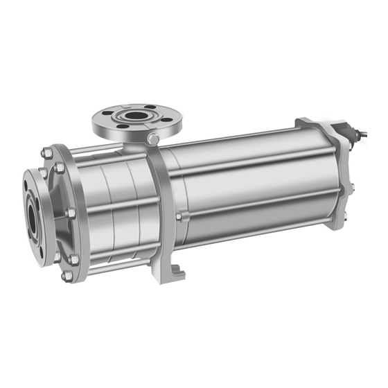
Refrigerant Pump
Original Operating Manual Series CAM / CAMh
Pos: 2 /Baureihe/Kälte/CAM/Deckblatt @ 0\mod_1303985759562_23.docx @ 1497 @ @ 1
=== Ende der Liste für Textmarke Deckblatt ===
Edition
BA-2021.01
Revision
7
Print-no.
1.0 EN
HERMETIC-Pumpen GmbH · Gewerbestraße 51 · D-79194 Gundelfingen · phone +49 761 5830-0 · www.hermetic-pumpen.com
Registergericht Freiburg HRB 365 · Geschäftsführer: Nicolaus Krämer (CEO, COO), Christiane Krämer (CFO), Sebastian Dahlke (CCO)
HERMETIC-Pumpen GmbH
Gewerbestrasse 51
D-79194 Gundelfingen,
Germany
phone +49 7615830-0
hermetic@hermetic-pumpen.com
http://www.hermetic-pumpen.com
We reserve the right to make technical changes.
Advertisement
Table of Contents

Related Manuals for HERMETIC-Pumpen CAM Series


Summary of Contents for HERMETIC-Pumpen CAM Series
- Page 1 We reserve the right to make technical changes. HERMETIC-Pumpen GmbH · Gewerbestraße 51 · D-79194 Gundelfingen · phone +49 761 5830-0 · www.hermetic-pumpen.com Registergericht Freiburg HRB 365 · Geschäftsführer: Nicolaus Krämer (CEO, COO), Christiane Krämer (CFO), Sebastian Dahlke (CCO)
-
Page 2: Table Of Contents
Table of contents Table of contents 1 About this operating manual .......................... 6 Target groups ............................ 6 Other applicable documents ......................6 Warnings and symbols ........................7 2 Safety 8 Intended use ............................. 8 2.1.1 Prevention of obvious misuse (examples) .................... 8 2.1.2 Residual risks and measures ....................... - Page 3 Table of contents 5.3.3 Installing the discharge pipe ......................25 5.3.4 Ensure stress-free pipe connections ....................26 Electrical connection ........................27 5.4.1 Providing a motor protection switch ....................27 5.4.2 Connecting the motor ........................27 Frequency converter operation ......................28 5.5.1 Approved frequency range .......................
- Page 4 List of figures List of figures Fig. 1: Pump type label (on the name plate) ....................12 Fig. 2: Motor type label (on the name plate) ....................12 Abb. 3: Typenschild (Beispiel) ......................... 13 Fig. 4: CAM layout (example CAM 2/3) ......................14 Fig.
- Page 5 List of tables List of tables Tab. 1: Target groups and their duties ......................6 Tab. 2: Other applicable documents and their purpose ..................6 Tab. 3: Warnings and consequences of disregarding them ................7 Tab. 4: Symbols and their meaning ........................7 Tab.
-
Page 6: About This Operating Manual
About this operating manual About this operating manual This manual: • Is part of the machine • Applies to all pump series listed • Describes safe and appropriate operation during all operating phases It is strictly prohibited to copy all or part of these instructions, to spread or to use them without authorization for competitive purposes or to release them to third parties. -
Page 7: Warnings And Symbols
About this operating manual Pos: 9 /Allgemein/01. Zu dieser Bedienungsanleitung/Warnhinweise und Symbole @ 0\mod_1303195181328_23.docx @ 759 @ 2 @ 1 Warnings and symbols Warning Risk level Consequences of disregard Immediate acute risk Death, serious bodily harm DANGER WARNING Immediate acute risk Death, serious bodily harm CAUTION Potentially hazardous situation Minor bodily harm... -
Page 8: Safety
Safety Safety The manufacturer does not accept any liability for damage resulting from disregard of any parts of this documentation. Pos: 12 /Allgemein/02. Sicherheit/Bestimmungsgemäße Verwendung @ 2\mod_1368604640328_23.docx @ 12936 @ 2 @ 1 Intended use • Only use the machine within the limits set by the technical specifications (... -
Page 9: Residual Risks And Measures
Safety Pos: 14 /Sparte/Kälte/02. Sicherheit/Restrisiken und Maßnahmen @ 2\mod_1368516899609_23.docx @ 12621 @ 3 @ 1 2.1.2 Residual risks and measures Residual risk Measures by the operating company Cuts while working without Observe warnings in the operating personal protective equipment. manual. Training for personnel. -
Page 10: General Safety Instructions
Safety Pos: 16 /Allgemein/02. Sicherheit/Allgemeine Sicherheitshinweise @ 0\mod_1303196836875_23.docx @ 777 @ 2 @ 1 General safety instructions Note the following regulations before carrying out any work. Pos: 17 /Allgemein/02. Sicherheit/Produktsicherheit @ 2\mod_1368602987984_23.docx @ 12861 @ 3 @ 1 2.2.1 Product safety The machine has been constructed according to the latest technology and recognized technical safety rules. -
Page 11: Obligations Of The Operating Company
Safety Pos: 18 /Allgemein/02. Sicherheit/Pflichten des Betreibers @ 2\mod_1368603025312_23.docx @ 12872 @ 34 @ 1 2.2.2 Obligations of the operating company Safety-conscious operation • Only operate the machine when in perfect technical condition and only use • intended, staying aware of safety and risks, and in adherence to the instructions in this manual. -
Page 12: Layout And Function
Layout and Function Layout and Function Pos: 25 /Baureihe/Kälte/CAM/Beschreibung @ 0\mod_1305095934703_23.docx @ 2321 @ 2 @ 1 Description Multi-level centrifugal pump with canned motor for boiling liquids or coolants. Pos: 26 /Baureihe/Kälte/CAM/Pumpen- und Motorentyp @ 0\mod_1306416278281_23.docx @ 2729 @ 2 @ 1 Label Fig. - Page 13 Layout and Function Abb. 3: Typenschild (Beispiel) Pump type Equipment no. / Serial no. Material no. Impeller diameter Motor type Connection Insulation class Degree of protection Duty type Standard Weight Date of manufacture Rated frequency Rated voltage Rated current Rated speed Rated output Cos ...
-
Page 14: Layout
Layout and Function Layout Fig. 4: CAM layout (example CAM 2/3) Impellers Pressure stage Front sleeve bearing Top shaft Connection cable Rear sleeve bearing Electrical winding Stator liner Stage casing Pos: 30 /Allgemein/04. Transport, Lagerung und Entsorgung/Transport, Lagerung und Entsorgung @ 0\mod_1303197757625_23.docx @ 795 @ 1 @ 1 14 / 49 Series CAM / CAMh BA-2021.01... -
Page 15: Transport, Storage And Disposal
Transport, Storage and Disposal Transport, Storage and Disposal Pos: 31 /Allgemein/04. Transport, Lagerung und Entsorgung/Transportieren @ 2\mod_1368605338671_23.docx @ 12980 @ 2 @ 1 Transport Weight specifications ( 3.2 Label, page 12). Pos: 32 /Allgemein/04. Transport, Lagerung und Entsorgung/Auspacken und Lieferzustand prüfen @ 2\mod_1368605341343_23.docx @ 12991 @ 3 @ 1 4.1.1 Unpacking and inspection on delivery 1. -
Page 16: Lifting
Transport, Storage and Disposal Pos: 35 /Allgemein/04. Transport, Lagerung und Entsorgung/Anheben @ 0\mod_1303299412781_23.docx @ 1151 @ 3 @ 1 4.1.2 Lifting Death or crushing of limbs may be caused by falling loads! Use lifting gear appropriate for the total weight to be transported. ... -
Page 17: Treatment For Storage
Transport, Storage and Disposal Pos: 39 /Allgemein/04. Transport, Lagerung und Entsorgung/Konservieren @ 0\mod_1303197987125_23.docx @ 804 @ 2 @ 1 Treatment for storage Not necessary for stainless materials. The preservation applied at the plant lasts for 12 months. NOTE Material damage may occur due to inappropriate treatment for storage! ... -
Page 18: Installation And Connection
Installation and connection Installation and connection Pos: 44 /Allgemein/05. Aufstellung und Anschluss/Hinweis Sachschaden durch Verunreinigungen @ 0\mod_1303198474390_23.docx @ 813 @ @ 1 NOTE Material damage can be caused by dirt! Do not remove any covers, transport and sealing covers until immediately before connecting the pipes to the pump. -
Page 19: Planning The Piping
Installation and connection Pos: 51 /Allgemein/05. Aufstellung und Anschluss/Rohrleitungen planen @ 2\mod_1368607392421_23.docx @ 13117 @ 2 @ 1 Planning the piping Pos: 52 /Allgemein/05. Aufstellung und Anschluss/Abstützungen und Flanschanschlüsse auslegen mit Hinweis @ 2\mod_1368607399234_23.docx @ 13139 @ 3 @ 1 5.2.1 Specifying supports and flange connections NOTE... -
Page 20: Specifying Pipe Lengths
Installation and connection Pos: 55 /Baureihe/Kälte/CAM/Rohrleitungslängen festlegen @ 0\mod_1305016574968_23.docx @ 2179 @ 34 @ 1 5.2.3 Specifying pipe lengths Calculate the minimum suction head (technical specification) Fig. 7: Supply pipe = NPSHR + R – minimum suction head [m] – resistance of the supply pipe [m] S –... -
Page 21: Providing Safety And Control Devices (Recommended)
Installation and connection Pos: 59 /Sparte/Kälte/05. Aufstellung und Anschluss/Sicherheits und Kontrolleinrichtungen @ 1\mod_1350465598437_23.docx @ 10452 @ 3 @ 1 5.2.6 Providing safety and control devices (recommended) 1. Provide a separator in the supply pipe. 2. Provide a vortex breaker in the vessel outlet. 3. -
Page 22: Fig. 9: Vessel Inlet/Vessel Outlet Arrangement
Installation and connection Pos: 65 /Sparte/Kälte/05. Aufstellung und Anschluss/Installationsempfehlungen - Anordnung Grafiken klein @ 2\mod_1369205615328_23.docx @ 14340 @ @ 1 Fig. 9: Vessel inlet/vessel outlet arrangement Vortex breaker Fig. 10: Vessel inlet/vessel outlet arrangement Vortex breaker Fig. 11: Parallel operation arrangement Vortex breaker Fig. - Page 23 Installation and connection Pos: 67 /Sparte/Kälte/05. Aufstellung und Anschluss/Automatische Entgasung @ 2\mod_1368709404703_23.docx @ 13735 @ 4 @ 1 Automatic venting 1. Install a non-return valve between the outlet flange and the gate valve to ensure the medium does not flow back when the pump is switched off. 2.
-
Page 24: Fig. 13: Automatic Venting (Single Pump - Parallel Pumps)
Installation and connection 3. For parallel operation: Separate supplies for the pumps – Separate bypass pipes – Pos: 68 /Sparte/Kälte/05. Aufstellung und Anschluss/Automatische Entgasung - Grafik mit Legende @ 2\mod_1368709426171_23.docx @ 13746 @ @ 1 Fig. 13: Automatic venting (single pump - parallel pumps) Qmin –... -
Page 25: Connecting The Pipes
Installation and connection Pos: 70 /Allgemein/05. Aufstellung und Anschluss/Rohrleitungen anschließen @ 0\mod_1303200164812_23.docx @ 831 @ 2 @ 1 Connecting the pipes Pos: 71 /Allgemein/05. Aufstellung und Anschluss/Verunreinigung der Rohrleitungen vermeiden @ 2\mod_1368608902000_23.docx @ 13172 @ 3 @ 1 5.3.1 Keeping the piping clean NOTE Material damage may occur due to impurities in the machine! ... -
Page 26: Ensure Stress-Free Pipe Connections
Installation and connection Pos: 75 /Allgemein/05. Aufstellung und Anschluss/Spannungsfreien Rohrleitungsanschluss sicherstellen @ 2\mod_1368608910078_23.docx @ 13205 @ 3 @ 1 5.3.4 Ensure stress-free pipe connections 1. Ensure that the permissible flange forces are not exceeded – the pump is not used as an anchor point for pipes –... -
Page 27: Electrical Connection
Installation and connection Pos: 76 /Sparte/Kälte/05. Aufstellung und Anschluss/Elektrisch anschließen @ 0\mod_1303200735562_23.docx @ 840 @ 2 @ 1 Electrical connection Risk of death due to electric shock! Have all electrical work carried out by qualified electricians only. DANGER Pos: 77 /Sparte/Kälte/05. Aufstellung und Anschluss/Motorschutzschalter vorsehen @ 2\mod_1368520779234_23.docx @ 12643 @ 3 @ 1 5.4.1 Providing a motor protection switch ... -
Page 28: Frequency Converter Operation
Installation and connection Pos: 82 /Sparte/Chemie/05. Aufstellung und Anschluss/Frequenzumrichterbetrieb @ 3\mod_1380270597750_23.docx @ 15672 @ 2 @ 1 Frequency converter operation The following instructions must be complied with for operation of the motor with frequency converters. Pos: 83 /Sparte/Chemie/05. Aufstellung und Anschluss/Frequenzumrichterbetrieb - Zugelassener Frequenzbereich @ 3\mod_1393933520000_23.docx @ 15981 @ 3 @ 1 5.5.1 Approved frequency range 1. -
Page 29: Installation And Operation
Installation and connection Pos: 85 /Sparte/Chemie/05. Aufstellung und Anschluss/Frequenzumrichterbetrieb - Installation und Betrieb @ 3\mod_1393933752156_23.docx @ 16003 @ 3 @ 1 5.5.3 Installation and operation NOTE Occurrence of leakage current! Install frequency converter and canned motor on a common earth potential. -
Page 30: Operation
Operation Operation Pos: 90 /Allgemein/06. Betrieb/Erstinbetriebnahme durchführen @ 0\mod_1303201556984_23.docx @ 849 @ 233 @ 1 Putting the machine into service for the first time 6.1.1 Identifying the machine type Identify the machine type ( technical specification). 6.1.2 Checking the shutdown period ... -
Page 31: Checking The Sense Of Rotation
Operation Pos: 95 /Sparte/Kälte/06. Betrieb/Betrieb Drehrichtung prüfen @ 0\mod_1303202179796_23.docx @ 858 @ 3 @ 1 6.1.4 Checking the sense of rotation 1. Switch on the motor. 2. Check the operating parameters or rotary field of the motor. NOTE Loosened threaded parts after operation with the wrong direction of rotation ... -
Page 32: Switching Off
Operation NOTE Risk of cavitation when throttling down the supply flow rate! Fully open the supply-side fitting and do not use it to adjust the delivery flow. Observe the permissible flow rate (→ technical specification). Pos: 102 /Sparte/Kälte/06. Betrieb/Hinweis - Sachschaden durch Überhitzung @ 2\mod_1368599544765_23.docx @ 12758 @ @ 1 NOTE Material damage caused by overheating! ... -
Page 33: Operating
Operation Pos: 105 /Sparte/Kälte/06. Betrieb/Betreiben (Überschrift) @ 0\mod_1303203007328_23.docx @ 867 @ 2 @ 1 Operating Pos: 106 /Sparte/Kälte/06. Betrieb/Betreiben Einschalten Teil 1 @ 2\mod_1368601926953_23.docx @ 12846 @ 3 @ 1 6.2.1 Turning on Pump initially put into service properly ... -
Page 34: Shutting Down The Machine
Operation Pos: 114 /Sparte/Kälte/06. Betrieb/Betrieb Außer Betrieb nehmen @ 2\mod_1368600277156_23.docx @ 12813 @ 2 @ 1 Shutting down the machine Risk of injury and poisoning due to hazardous pumped liquids! Safely collect any leaking pumped liquid and dispose of it in accordance with environmental rules and requirements. -
Page 35: Operating The Stand-By Pump
Operation Operating the stand-by pump 1. Preparing the stand-by pump: Putting the pump into service for the first time – ( 6.1 Putting the machine into service for the first time, page 30). – Filling and bleeding the stand-by pump. –... -
Page 36: Maintenance
Maintenance Maintenance Pos: 120 /Allgemein/07. Wartung und Instandhaltung/Für Montagen und Reparaturen @ 2\mod_1368628330109_23.docx @ 13545 @ @ 1 Trained service technicians are available for fitting and repair work. Present a pumped medium certificate (DIN safety data sheet or safety certificate) when requesting service. -
Page 37: Repairs
Maintenance Pos: 128 /Allgemein/07. Wartung und Instandhaltung/Instandhalten @ 0\mod_1305188066359_23.docx @ 2454 @ 2 @ 1 Repairs Pos: 129 /Allgemein/07. Wartung und Instandhaltung/Gefahr-Verletzungsgefahr durch laufende Pumpe @ 2\mod_1368625689500_23.docx @ 13501 @ @ 1 Risk of injury due to running machine! Do not touch the running machine. ... -
Page 38: Dismounting
Maintenance Pos: 134 /Sparte/Kälte/07. Wartung und Instandhaltung/Demontieren @ 0\mod_1303287019468_23.docx @ 1105 @ 34 @ 1 7.2.1 Dismounting NOTE Material damage may occur due to inappropriate dismantling! Warm up immobile bearing sleeves. Preparations for dismounting Machine unpressurized Machine completely empty, flushed and decontaminated ... -
Page 39: Fig. 14: Dismounting The Carbon Bearing - Cam
Maintenance Pull out 819 with 821 carefully to the front. Make sure that 816 is not damaged – CAMh 529.01 525.01 932.01 940.01 529.02 472.01 529.01 917.00 552.02 472.02 529.02 914.05 930.05 545.02 CAMh To dismount the motor-side carbon To dismount the motor-side carbon bearing 545.02 (only for motors bearing 545.04 (only for motors AGX 3.0, 4.5 and 6.5):... -
Page 40: Returning The Pump To The Manufacturer
Maintenance Dismounting the stator: Detaching the parts in the following sequence: CAMh 920.12 900.05 160.00 160.00 • When doing this, label the electric supply lines and disconnect at the connection point. 816.00 816.00 • Press out of the stator in the direction of the pump. 812.01 812.01 Inspect the stator winding for possible damage:... -
Page 41: Installing
Maintenance 7.2.3 Installing Preparations for mounting 1. Observe the following during the installation: Replace worn parts with genuine spare parts. – Replace seals. – Maintain the prescribed tightening torques ( 1.2 Other applicable – documents, page 6). Reinstall the components concentrically and straight in accordance –... -
Page 42: Ordering Spare Parts
Maintenance Pos: 144 /Allgemein/07. Wartung und Instandhaltung/Ersatzteile bestellen @ 0\mod_1303205433125_23.docx @ 899 @ 2 @ 1 Ordering spare parts For trouble-free replacement in the event of faults, we recommend keeping entire insert units or spare pumps available on site. The application guidelines conforming to DIN 24296 recommend provisioning for two years of continuous use (... -
Page 43: Troubleshooting
Troubleshooting Troubleshooting Pos: 147 /Allgemein/08. Störungsbehebung/Fehlerbilder @ 0\mod_1303205588843_23.docx @ 908 @ 2 @ 1 Malfunctions Possible malfunctions are identified by a number in the following table. This number identifies the respective cause and remedy in the troubleshooting list. Malfunction Number Machine not pumping Pumping rate insufficient Pumping rate excessive... - Page 44 Troubleshooting Malfunction number Cause Elimination ‒ ‒ ‒ ‒ ‒ ‒ ‒ ‒ Transport and sealing cover still in Remove the transport and place sealing cover. Dismantle the machine and ‒ ‒ ‒ ‒ ‒ ‒ ‒ ‒ check for dry-run damage.
-
Page 45: Contact The Manufacturer
Pos: 149 /Allgemein/08. Störungsbehebung/Kontakt mit dem Hersteller aufnehmen @ 6\mod_1458565281437_23.docx @ 33298 @ 2 @ 1 Contact the manufacturer Should there be any problems or questions, please contact: customer-service@hermetic-pumpen.com Pos: 151 /Allgemein/09. Anhang/Anhang @ 0\mod_1303206142515_23.docx @ 917 @ 122 @ 1 1.0 EN BA-2021.01... -
Page 46: Appendix
Appendix Appendix Recommended spare parts Detailed ordering information ( parts list). Item no. Designation 400.XX Gaskets 545.01/02 Bearing bushes 529.01/02 Bearing sleeves Strainer insert Tab. 11: Recommended spare parts Technical specifications See technical specification. Pos: 152 /Sparte/Kälte/09. Anhang/Umgebungsbedingungen @ 0\mod_1303292209265_23.docx @ 1132 @ 3 @ 1 9.2.1 Ambient conditions Ambient temperature: -50 °C to 50 °C... -
Page 47: Safety Certificate
Appendix Pos: 155 /Allgemein/09. Anhang/Unbedenklichkeitsbescheinigung @ 0\mod_1303306859734_23.docx @ 1203 @ 2 @ 1 Safety certificate Please copy this document and send it together with the machine. 1.0 EN BA-2021.01 Series CAM / CAMh 47 / 49... -
Page 48: Fig. 16: Safety Certificate
Appendix Fig. 16: Safety certificate Pos: 156 /zz.Layoutmodule/Seitenumbruch @ 0\mod_1309158040077_23.docx @ 4191 @ @ 1 48 / 49 Series CAM / CAMh BA-2021.01 1.0 EN... -
Page 49: Declarations In Accordance With The Ec Machinery Directive
Appendix Pos: 157 /Allgemein/09. Anhang/Erklärungen nach EG-Maschinenrichtlinie @ 0\mod_1303206348218_23.docx @ 926 @ 2 @ 1 Declarations in accordance with the EC Machinery Directive Pos: 158 /Sparte/Kälte/09. Anhang/Konformitätserklärung nach EG-Maschinenrichtlinie @ 0\mod_1303292344046_23.docx @ 1141 @ 3 @ 1 9.4.1 Declaration of conformity in accordance with the EC Machinery Directive The following declaration does not include a serial number or signatures.
Need help?
Do you have a question about the CAM Series and is the answer not in the manual?
Questions and answers