
Related Manuals for Telecrane F24-60


Summary of Contents for Telecrane F24-60
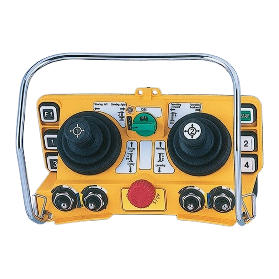
- Page 1 F24-60 Industrial Remote Controller Operating Manual TELECRANE Lee’s Hi-Tech Ent. Co., Ltd.
-
Page 2: Warranty & Precautions Of Operation
Table of Contents Warranty & Precautions of Operation..………….……...2 F24-60 Operation………………...…………….….…….4 F24-60 Software Quick Start ……………………..…….8 Definition of Function Terminology……………..……13... - Page 3 N ever dismantle the equipment by any unauthorized personnel, or equipment may be damaged. Ł ‡After finishing operation of TELECRANE radio controller shut off main power to the crane, power to receiver, and remove transmitter key. If transmitter’s power is controlled by “rotary key switch”, then need turn the key to “OFF”...
-
Page 4: F24-60 Operation
(4) 220/380 VAC Changing Frequency & identify frequency quartz It’s easy to change frequency of new F24-60. The frequency can be changed simply by replacing correspondent frequency quartz into both TX and RX. Note: There are 2 types of frequency are available: VHF and UHF. Do not replace the VHF quartz unit into UHF transmitter or receiver. - Page 5 Instructions: (1). Pry up the existing quartz unit with a flat screwdriver (2). Remove the quartz unit from the RF module. (3). Straight up both pins of the new quartz unit with pliers. (4). Insert new quartz unit vertically into the RF module. (5).
- Page 6 Changing receiver power supply voltage Disconnect receiver power. Remove transformer connector plug from original position (Fig A) Then insert connector plug into new position (Fig B) 220V 110V 110V 220V 380V 220V (Fig. A) (Fig. B) NC/NO output connection Relay module are designed for both type of relay such NO and NC/NO. Both outputs connection of NC/NO relay are available on the relay module.
- Page 7 Transmitter red/yellow LED The joystick #2 memory is damaged. Contact the distributor for indicator flashing crossly service. when start key switch on Red LED indicator flashing Transmitter main memory is damaged. Contact the distributor quickly when start key for service. switch on Transmitter red LED indicator remains on...
-
Page 8: F24-60 Software Quick Start
F24-60 Software Quick Start I. RELAY SELECTION Select quantity of relay to be used for each buttons, selector switch and joystick. (1) Choose COM PORT for your interface is assign (2) Press READ R/C (It may take a while to download the data from transmitter or receiver) (3) Pull down the menu and changing the number of relay to be used of each command. - Page 9 II. FUNCTION SETTING Choose the function for selected buttons, selector switch, joystick and transmitter/receiver parameters. 1) Changing the setting as need and press NEXT when ready Note: You may return to previous step by press RETURN at any time. Refer to annex I for further explanation of all parameters.
- Page 10 III. JOYSTICK SETTING Joystick relay editing Joystick Setting is divided into 4 parts (1) Joystick No. 1 Y axis (2) Joystick No. 1 X axis (3) Joystick No. 2 Y axis (4) Joystick No. 2 X axis (1) Click relay table to edit relay output according to the command. Leave blank for disable.
- Page 11 IV. USER INFORMATION Save user information as record for future use. (1) Fill the necessary information as need. (2) Press WRITE R/C when ready to overwrite the existing data on transmitter or receiver. Note: You may return to previous step by press RETURN at any time. The user information is not saving in either transmitter or receiver memory, and it will be only saving into PC with D24 file format.
- Page 12 V. PRINT PREVIEW Print Preview allows you to have a print copy of receiver wire output which corresponding with all commands. (1) Press the printer icon to print the page. Note: Receiver output wire number is varied with command every time you change the settings.
-
Page 13: Definition Of Function Terminology
(Annex I) Definition of Function Terminology The relative relay is “ON” when the pushbutton is pressed and held; and relay Normal is “off” when the pushbutton is released. Maintained function: the relay is operated by pressing and releasing; press Toggle and release again to turn off the relay. - Page 14 Power Saving Mode: By using firmware to control frequency transmission Power Saving cycle period, thus to reduce power consumption of transmitter. Note: the operating distance will be decreased when the “Power Saving” mode is activated. “Non-continuous transmitting mode”: After “Power-On”, the transmitter Transmit Mode will transmitting the signal only when the pushbutton is pressed.
Need help?
Do you have a question about the F24-60 and is the answer not in the manual?
Questions and answers