Table of Contents
Advertisement
Quick Links
860-7100-19 DTU Operation Manual
OPERATION
MANUAL
Engineered Lifting Systems and Equipment, Inc. DBA Gorbel Canada
T (800) 263-9823 | F (519) 669-9047 | www.gorbel.com
275 Union Street | Elmira, ON N3B 3P1 | Canada
Original Instructions
Destuff-it
Models:
DTU2, DTU3, DTU7,
DTU9, DTU10, DTU12
Unloader
TM
1
Advertisement
Table of Contents

Related Manuals for GORBEL Destuff-it DTU2


Summary of Contents for GORBEL Destuff-it DTU2
- Page 1 Engineered Lifting Systems and Equipment, Inc. DBA Gorbel Canada T (800) 263-9823 | F (519) 669-9047 | www.gorbel.com 275 Union Street | Elmira, ON N3B 3P1 | Canada OPERATION Original Instructions Destuff-it Unloader MANUAL Models: DTU2, DTU3, DTU7, DTU9, DTU10, DTU12...
-
Page 2: Table Of Contents
TABLE OF CONTENTS TABLE OF CONTENTS .............2 CONNECT CONVEYOR TO REMOTE PANEL ....30 MACHINE SPECIFICATIONS ..........3 CONNECT POWER TO REMOTE PANEL ......30 CE DECLARATION OF CONFORMITY ......4 START-UP SEQUENCE ..........31 INTRODUCTION ...............5 QUICK START GUIDE WITH MANUFACTURER INFORMATION ........5 FLEXIBLE CONVEYOR ...........32 WARRANTY POLICY ............6 FLEXIBLE CONVEYOR SAFETY WARNINGS ............6... -
Page 3: Machine Specifications
MACHINE SPECIFICATIONS Thank you for purchasing a Destuff-it Unloader from Engineered Lifting Systems & Equipment, Inc. DBA Gorbel Canada (ELS). ® This manual contains valuable safety and operation information. Ensure operators read the SAFETY and OPERATING sections of this manual prior to operating your new machine. -
Page 4: Ce Declaration Of Conformity
CE DECLARATION OF CONFORMITY 01-13-2023 CE Declaration of Conformity Hereby, Gorbel Inc., declares that this material handling equipment is in compliance with the essential requirements and other relevant provisions listed below. ----------------------------------------------------------------------------------------------------------------------------------------------- EMC Directive: 2014/30/EU Standard EN 61000-6-4:2007 +A1 :2011 Electromagnetic compatibility (EMC) –... -
Page 5: Introduction
INTRODUCTION MANUFACTURER INFORMATION Thank you for purchasing a Destuff-it Unloader. This manual Engineered Lifting Systems & Equipment, Inc. DBA Gorbel ® provides safety and operation information for the machine. Canada (ELS) 275 Union Street, Elmira, ON Canada N3B 3P1 When maintained and operated properly, the unit is designed to provide many years of reliable service. -
Page 6: Warranty Policy
WARRANTY POLICY d) Any incidental, indirect, special or consequential damages. e) Wear items. Engineered Lifting Systems & Equipment, Inc. DBA Gorbel ® SHIPPING: It is the responsibility of the customer to inspect all Canada (ELS) warrants their equipment, when shipped, and their... -
Page 7: Notice To All Operators
NOTICE TO ALL OPERATORS • NEVER operate this equipment without completing daily inspection checklist. • NEVER operate machine if safety devices have been altered KNOW YOUR EQUIPMENT or disabled. • NEVER operate a potentially defective machine. Operators of this unit must be familiar with its principal parts and •... -
Page 8: Reasonably Foreseeable Misuse
REASONABLY FORESEEABLE MISUSE • Do not operate machine with persons on the machine base. • Do not use machine in a wet environment. • Do not drive machine on unstable surface, off the side of Do not operate above design capacities. dock plate or over holes. -
Page 9: Iso Graphical Symbols Legend
ISO GRAPHICAL SYMBOLS LEGEND (For warning labels on the Destuff-it Restuff-it machines) SYMBOL OR LABEL DEFINITION This is the safety alert symbol. It is used to alert to potential personal injury hazards. Obey all safety messages that follow this symbol to avoid a possible injury or death. The addition of this symbol to a DANGER or WARNING safety label indicates that an electrical hazard exists, which will result in personal injury if the instructions are not... - Page 10 ISO GRAPHICAL SYMBOLS LEGEND (For warning labels on the Destuff-it Restuff-it machines) SYMBOL OR LABEL DEFINITION AREA SCANNER LABEL REAR SCANNER FAULTS (RIGHT / REVERSE / LEFT) REVERSE SCANNER BYPASS RECOMMENDED ZERO POINT TURN RECOMMENDED FORWARD SCANNER FRONT SCANNER FAULTS (RIGHT / FORWARD / LEFT) E0604R1 BATTERY CHARGER...
- Page 11 ISO GRAPHICAL SYMBOLS LEGEND (For warning labels on the Destuff-it Restuff-it machines) SYMBOL OR LABEL DEFINITION POWER ON FAULT REMOTE STOP RUN AND JOG CONVEYOR RESET START 860-7100-19 DTU Operation Manual...
- Page 12 MACHINE OVERVIEW 860-7100-19 DTU Operation Manual...
-
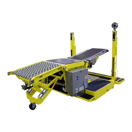
Page 13: Machine Overview
MACHINE OVERVIEW Power Supply Operator Platform Connection Remote Panel Pivoting Conveyor (Mobile or Anchored) Drive Panel End of Travel Sensor Middle Conveyor Lockable Casters Battery Rear Conveyor Remote Section Conveyor (additional conveyor sections are optional) Rear Area Scanner (optional) Control Panel Pressure Sensing Safety Mats (two on both sides of machine) Lifting Points (two on both sides of machine) LED Light Strips (on both masts) - Page 14 UNLOADING THE MACHINE 860-7100-19 DTU Operation Manual...
-
Page 15: Unloading The Machine
UNLOADING THE MACHINE ONLY AUTHORIZED PERSONNEL SHOULD DRIVE THE 6. Ensure your weight is on operator sensing mat when standing DESTUFF-IT on operator platform. 1. Remove all packing materials and tether straps. Roll out remote section and conveyor (if applicable). 2. - Page 16 FACILITY POWER SUPPLY 860-7100-19 DTU Operation Manual...
-
Page 17: Facility Power Supply
FACILITY POWER SUPPLY All electrical installations and connections are to be made by ONLY AUTHORIZED PERSONNEL SHOULD CONNECT qualified installation personnel and adhering to national and local POWER SUPPLY TO THE REMOTE PANEL. PERSONNEL codes. MUST ALWAYS FOLLOW PROPER PROCEDURES AND WEAR APPROPRIATE PPE. -
Page 18: Phasing
PHASING After connecting power supply to the Remote Panel, phasing must be verified. If phasing is correct, the LED Status on the Phasing Monitor Device (PMD) will be green and the White Power Light on the door of the Remote Panel will turn on. If phasing is reversed, the White Power Light on the door of the Remote Panel will not turn on. - Page 19 MACHINE COMPONENTS 860-7100-19 DTU Operation Manual...
-
Page 20: Machine Components
MACHINE COMPONENTS Modular front belt, middle belt, gravity wheel conveyor REMOTE PANELS Mounted in Stand (Anchored) Mounted in Remote Section (Mobile) 860-7100-19 DTU Operation Manual... -
Page 21: Control Panel
CONTROL PANEL REMOTE PANEL White Power ON Light E-Stop Button E-Stop Button Power ON Light Green START Button Fault Light Ground Fault Red LED Indicator Remote Stop Light Ground Check Green LED Indicator Conveyor Start/Stop Selector Switch (if equipped) Control Panel OPERATOR PLATFORM Control Panel Operator platform is equipped with following features:... -
Page 22: Emergency Stop (E-Stop) Buttons
EMERGENCY STOP (E-STOP) BUTTONS There are 5 E-Stop buttons on each unit. E-Stop buttons are located on the control panel, drive panel, remote panel and both sides of front pivoting conveyor. Pressing an E-Stop button will stop all machine motion immediately. Rotate E-Stop buttons gently to release. -
Page 23: Batteries
BATTERIES Maintenance Instruction Notes ODYSSEY® batteries are very different from standard liquid- Batteries (2) 120VAC power cord acid batteries that are openly vented. ODYSSEY battery is and Battery Charger Step-down Transformer operates as a sealed battery, recycling nearly all gases internally under normal operating conditions. -
Page 24: Battery Chargers
BATTERY CHARGERS B) NOCO GENIUS® GENPRO (IF SO PROVIDED) If machine uses a NOCO Genius® GENPRO10X2 Battery A) XANTREX TRUECHARGE (IF SO PROVIDED) ® Charger model 10amp x 2 (12V): If machine uses a Xantrex TrueCharge 2 Battery Charger ® model TC2024 (20A, 24VDC): WARNING: SHOCK HAZARD Truecharge 2 Battery... -
Page 25: Rotary Handle
SENSORS Operator Sensing Mat ROTARY HANDLE Sensing Edge (when equipped) Pressure Sensing Safety Mats Use rotary handle for conveyor UP/DN or to steer when travelling. Area Scanners (when equipped) Gripping rotary handle releases brake allowing side to side front conveyor motion. Rotating rotary handle moves platform and/or pivoting conveyor up and down. -
Page 26: Operator Controls
OPERATOR CONTROLS D - Machine Travel - Turn selector switch to move machine forward or backwards. Hold selector switch in position to maintain travel in desired direction. CONTROLS ON PIVOTING CONVEYOR E - Machine Rotate - Turn selector switch to rotate unit either clockwise or counterclockwise. -
Page 27: Fault Codes
FAULT CODES Three lights of selector switches (B, D, E) flash and beep to Unit has a fan located at top of right mast and can be used to announce a fault. Codes are as follows: direct air flow. Switch is located just below the fan. One Flash/Beep Sensor fault Objects putting pressure on the mats... - Page 28 STARTING THE MACHINE 860-7100-19 DTU Operation Manual...
-
Page 29: Starting The Machine
STARTING THE MACHINE Ensure front conveyor legs are raised 3 inches off the ground. If this step is not followed, damage will occur IMPORTANT: Only persons who are appropriately trained and to the flex conveyor. It is recommended that two people qualified with the safe operation and service of this machine connect conveyor to machine. -
Page 30: Connect Conveyor To Remote Panel
CONNECT POWER TO REMOTE PANEL CONNECT CONVEYOR TO REMOTE PANEL Method 1: Method 1: Suspended Power Drop (connected to cable in post in the Remote Section) Ensure power supply from the building is OFF. Connect Remote Panel to facility’s power supply with Meltric Connector at the end of the post in the Remote Section. -
Page 31: Start-Up Sequence
START-UP SEQUENCE Stand on operator platform. 1. Turn facility fused disconnect to ON position. 7. Press green START button on pivoting conveyor. Button will illuminate green when started. Wait 20 seconds for PLC to 2. Verify all 5 E-Stops are released (by rotating clockwise). start. -
Page 32: Quick Start Guide With Flexible Conveyor
QUICK START GUIDE WITH FLEXIBLE CONVEYOR WARNING: DO NOT operate the Destuff-it machine without 10. To start conveyor, rotate the Belt Motion Control Switch (D). proper authorization. Failure to avoid this hazard could Check that the conveyor belt direction is moving according to result in serious injury. - Page 33 FLEXIBLE CONVEYOR (when provided) 860-7100-19 DTU Operation Manual...
-
Page 34: Flexible Conveyor
FLEXIBLE CONVEYOR pivoting conveyor towards the front of the machine. NOTE: If the blue light on the left mast is on, the sensing mats need to be reset for belts to run. Turn Belt Motion selector switch OPERATING CONVEYOR towards the back; hold for 2 seconds; the blue light will turn off if the mats have been reset. -
Page 35: Procedure To Safely Disconnect Flex Conveyor
PREVENTIVE MAINTENANCE ALWAYS disconnect flex conveyor when container/trailer is fully unloaded and push it manually out of container/trailer. Daily Maintenance NOTE: Conveyors should be started and allowed for a few Keep conveyor clean and free of debris, dirt and grease mintues to warm up O-Rings. - Page 36 OPERATING THE MACHINE 860-7100-19 DTU Operation Manual...
-
Page 37: Operating The Machine
OPERATING THE MACHINE OPERATOR RESPONSIBILITIES FOR MAINTENANCE Serious injury could result from using a Destuff-it machine that is This section provides necessary information needed to operate not properly maintained or kept in good working condition. the Destuff-it machine. It is important for all users to read and understand this section prior to operating the machine. -
Page 38: Driving Instructions
DRIVING INSTRUCTIONS DESTUFFING: UNLOADING CONTAINER • Remember to use proper technique when loading product on ALWAYS ensure clearance of obstructions before driving unit machine. toward dock. • Always position the machine close to the box wall. • Place the pivoting conveyor in front of the box to be ALWAYS drive the machine with the operator platform raised transferred. -
Page 39: Daily Operation Checklist
DAILY OPERATION CHECKLIST DAILY OPERATIONS DESTUFF-IT RESTUFF-IT CHECKLIST [Operator’s Daily/Pre-Shift Inspection Form] Unit #: Department: Date: Operator’s Name: No. of Hours on Machine: ITEM # INSPECT CHECK FOR PASS FAIL Electrical Cables and Damaged connectors or latches. Check for kinked, worn, or Connectors damaged electrical cables. -
Page 40: Transportation And Storage
TRANSPORTATION AND STORAGE 860-7100-19 DTU Operation Manual... -
Page 41: Transporting The Machine
TRANSPORTING THE MACHINE OPERATOR RESPONSIBILITIES FOR SAFE TRANSPORTATION This section provides necessary information needed to safely Serious injury could result from not following the proper transport the Destuff-it machine within a warehouse operation. precautions or using a forklift that is not properly maintained. It is not intended to cover normal operation and use which are Operator is responsible for making sure the forklift has been covered under other sections of this manual. -
Page 42: Preventing Battery Rundown (For Long Term Storage)
PREVENTING BATTERY RUNDOWN (FOR Step 2 - Remove the 4 thumb screw knobs and washers that secure the guard over top of the batteries. Remove the guard LONG TERM STORAGE) and place it on the machine in a safe place. Reinstall the thumb screws and washers to prevent them from being lost. -
Page 43: Safe Handling
SAFE HANDLING Do not operate machine: • Unless trained and authorized. • Unless operator manual is read and understood. • Unless mentally and physically capable of following machine instructions. • Under the influence of alcohol or drugs. • While using a cell phone or other types of electronic devices. •... - Page 44 OPTIONS 860-7100-19 DTU Operation Manual...
-
Page 45: Options
OPTIONS Depending on the options you choose to be included in your Destuff-it unit, your machine may have the following features: SENSORS The Destuff-it machine may use a forward sensing edge switch to stop forward travel if the machine impacts an object. The machine will stop driving forward and the conveyor belts will shut off. -
Page 46: Network Integration
NETWORK INTEGRATION EXTENDED OPERATOR PLATFORM If your machine has Network Integration, the Remote, Control The Standard Operator Platform has a depth of 23.13” and the and Drive Panels will appear different. The Network cable will be Extended Operator Platform has a depth of 32.56”. integrated in the panels and will connect to an ethernet port at the Rear Conveyor. -
Page 47: Spanish
SPANISH 860-7100-19 DTU Operation Manual... -
Page 48: Guía Rápida De Inicio Y Funcionamiento
GUÍA RÁPIDA DE INICIO Y FUNCIONAMIENTO ADVERTENCIA: NO opere la máquina Destuff-it™ o Restuff-it™ sin la los tapetes laterales deben ser reiniciados. Gire hacia atrás debida autorización. El no obedecer esta advertencia puede ocasionar el botón de Movimiento de las Bandas (D), sosténgalo por segundos, lesiones graves. -
Page 49: Descargando Su Máquina
DESCARGANDO SU MÁQUINA 6. Asegúrese de que su peso se encuentre sobre del tapete de detección del operador cuando se encuentre sobre la plataforma SOLAMENTE PERSONAL AUTORIZADO PUEDE del operador. CONDUCIR LA MAQUINA DESTUFF-IT™. 1.Retire todo el material de embalaje y las correas de sujeción. Manualmente mueva la sección remota y la banda transportadora (si corresponde) fuera del camión.
Need help?
Do you have a question about the Destuff-it DTU2 and is the answer not in the manual?
Questions and answers