
Related Manuals for CUH SDVC31 Series


Summary of Contents for CUH SDVC31 Series
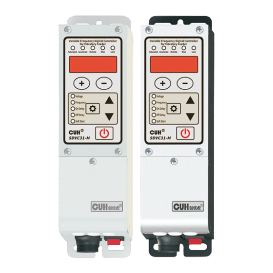
- Page 1 Variable Frequency Digital Controller for Vibratory Feeder SDVC31 Series User Manual...
- Page 2 CUH enjoys and reserves all rights conferred by copyright law and other laws. Without the written consent of CUH, part or all of this user manual shall not be copied, translated, imitated or otherwise utilized.
- Page 3 Variable Frequency Digital Controller for Vibratory Feeder SDVC31 Series Preface Thank you for choosing CUH SDVC31 series digital frequency modulation vibration feeding controller. (The controller for short in the following text). This series of controllers uses high-quality components and incorporates the latest electronic technology, and is carefully designed with high-performance digital signal processors.
- Page 4 Never open the controller shell to avoid electric shock. Contact Essential CUH if the controller break down. Never try to repair the controller yourself which may caused void warranty. 2023-08 SDVC31SMSEN_4.01...
- Page 5 Variable Frequency Digital Controller for Vibratory Feeder SDVC31 Series Operating and Storage Environment Inspection Before Using Every controller will go through rigorous quality inspection before delivery and is packed with crash-proof packaging, Please check the following items after unpacking 1. Whether the controller is damaged during transportation.
- Page 6 Variable Frequency Digital Controller for Vibratory Feeder SDVC31 Series 2023-08 SDVC31SMSEN_4.01...
-
Page 7: Table Of Contents
Variable Frequency Digital Controller for Vibratory Feeder SDVC31 Series Contents Chapter Ⅰ Before Use ------------------------------------------------------------------------ 1.1 Check the Package Contents ----------------------------------------------------------1 1.2 Indicators, Buttons and External Parts Explanation ----------------------------- 1.3 Wiring Ports Explanation --------------------------------------------------------------- 1.4 Nameplate Explanation ----------------------------------------------------------------- Chapter Ⅱ Features ---------------------------------------------------------------------------4 Chapter Ⅲ... - Page 8 Variable Frequency Digital Controller for Vibratory Feeder SDVC31 Series 5.4 Logical Relation Setting of the Control Signal-----------------------------------22 .5 Control Output -------------------------------------------------------------------------- 5.5.1 Wiring Method of Control Output---------------------------------------------23 5.5.2 Logical Relation Setting of the Controlling Output-----------------------24 5.5.3 Main Control Separation Parameter -----------------------------------------25 5.6 Maximum Output Voltage Limit ----------------------------------------------------26...
-
Page 9: Chapter Ⅰbefore Use
Variable Frequency Digital Controller for Vibratory Feeder SDVC31 Series Chapter ⅠBefore Use This chapter introduces product package contents, controller appearance description and controller nameplate information. 1.1 Check the Package Contents Before using, please check the integrity of the controller and accessories. If you find that the product is defective or damaged, missing accessories, etc., please... -
Page 10: Indicators, Buttons And External Parts Explanation
Variable Frequency Digital Controller for Vibratory Feeder SDVC31 Series 1.2 Indicators, Buttons and External Parts Explanation Remote Speed Control Indicator: Stop Indicator: The indicator lights up when The indicator lights up as the Acceleration Indicator: Remote Speed Control signal is... -
Page 11: Wiring Ports Explanation
Max Output Current: 3.0A Max Output Power: 660VA Serial Number For use at altitude 2000m or lower Manufacturer Nanjing CUH Science & Technology Co.,Ltd and address Add.:Building 2, Xueyan Tech Park, Tuscity, No.9 Zhineng Rd, Jiangning, Nanjing, China Serial Number Description INS01... -
Page 12: Chapter Ⅱ Features
Variable Frequency Digital Controller for Vibratory Feeder SDVC31 Series Chapter Ⅱ Features The controller is specially designed for controlling vibratory feeder in the automation systems. Combined with the latest electronic technology and elaborate design, the controller provides the following convenient and practical features: Frequency Adjusting: Output Frequency ranges from 40.0Hz to 400.0Hz. - Page 13 CUH attaches great importance to the product quality management and safety performance. Apart form the high-quality components we use and rigorous quality control system, CUH has taken account of possible accidents users may encounter and provides the following protective functions to maximum the controller's practicability.
-
Page 14: Chapter Ⅲ Installation Guide
Variable Frequency Digital Controller for Vibratory Feeder SDVC31 Series Chapter Ⅲ Installation Guide This chapter introduces the necessary conditions for the use of the controller and how to install and connect it correctly. 3.1 Controller Usage Conditions The controller is powered by AC 110/220V, and the protective ground connection is made through the plug of the power cord. -
Page 15: Install And Use
Variable Frequency Digital Controller for Vibratory Feeder SDVC31 Series 3.3 Install and Use Step One: Open the packing box and check the controller and all accessories. Step Two: Connect the wiring terminals of the Output Power Cable to the vibrator's electromagnetic coil. - Page 16 Variable Frequency Digital Controller for Vibratory Feeder SDVC31 Series Step Three: Connect the Connector of the Input Power Cable Variable Frequency Digital Controller for Vibratory Feeder to the Input Power Socket of the controller. Saturated Accelerate Remote Stop Lock Voltage...
- Page 17 Variable Frequency Digital Controller for Vibratory Feeder SDVC31 Series Step Five: Variable Frequency Digital Controller for Vibratory Feeder Turn on the power switch of the Remote Stop Saturated Accelerate Lock controller, and the voltage "U 150 " Output Voltage should be displayed and Voltage...
- Page 18 Variable Frequency Digital Controller for Vibratory Feeder SDVC31 Series Step Seven: Variable Frequency Digital Controller for Vibratory Feeder Long press to exit the output Saturated Accelerate Remote Stop Lock U means frequency "E" and returns to the Output Voltage voltage adjustment parameter,...
-
Page 19: Chapter Ⅳ Basic Function Description
Variable Frequency Digital Controller for Vibratory Feeder SDVC31 Series Chapter Ⅳ Basic Function Description This chapter introduces basic parameter settings. 4.1 Output Voltage Output voltage rectified mean value of the controller can be set directly and digitally through the keypad. Benefit from the unique voltage stabilizing... -
Page 20: Output Frequency
Variable Frequency Digital Controller for Vibratory Feeder SDVC31 Series 4.2 Output Frequency The controller adopts direct digital frequency synthesis technology (DDS), which has very high frequency accuracy and stability, and does not change with time and temperature. Press and hold for 2 seconds to... -
Page 21: On/Off Delay Of Intelligent Photoelectric Sensor
Variable Frequency Digital Controller for Vibratory Feeder SDVC31 Series 4.3 On/Off Delay of Intelligent Photoelectric Sensor When using a sensors or PLC to turn on or turn off the controller's main output, the action can be delayed for a period of time after the control signal is given or restored. -
Page 22: Soft Startup Time
Variable Frequency Digital Controller for Vibratory Feeder SDVC31 Series 4.4 Soft Startup Time In order to avoid sudden shock to the vibrator coil, the controller can gradually increase output voltage from 0 to the preset value when startup Soft Startup Time ( t ): The period of time it takes for the controller to smoothly rise its output voltage from 0 to the preset value when startup. -
Page 23: Chapter Ⅴ Advanced Function Description
Variable Frequency Digital Controller for Vibratory Feeder SDVC31 Series Chapter Ⅴ Advanced Function Description This chapter introduces advanced parameter settings. 5.1 Remote Speed Control The controller supports external analog signal to control output voltage, analog signal supports potentiometer, 1~5V voltage, 4~20mA current. - Page 24 Variable Frequency Digital Controller for Vibratory Feeder SDVC31 Series 1~5V voltage control connection 1~5V Speed Ctrl Photosensor Sensor Ctrl Out 4~20mA current control connection Speed Ctrl 4~20mA Photosensor Sensor Ctrl Out 2023-08 SDVC31SMSEN_4.01...
-
Page 25: Intelligent Photoelectric Sensing
Variable Frequency Digital Controller for Vibratory Feeder SDVC31 Series 5.2 Intelligent Photoelectric Sensing The intelligent photoelectric port of this controller supports photoelectric through- beam or reflection sensors composed of light-emitting diodes and phototransistors, and can also be set to support NPN switch sensors. The specific wiring diagram is as follows:... -
Page 26: Logical Relation Setting Of The Intelligent Photoelectric Sensor
Variable Frequency Digital Controller for Vibratory Feeder SDVC31 Series 5.2.2 Logical Relation Setting of the Intelligent Photoelectric Sensor Under normal circumstances, the receiving end receives no optical signal, and the controller runs by default. But in some special applications the controller needs to be stopped when the receiving end receives no optical signal. -
Page 27: Switch Sensor
Variable Frequency Digital Controller for Vibratory Feeder SDVC31 Series 5.3 Switch Sensor Switch Sensor port can support NPN, PNP, Ut1, Ut0 modes. The Ut1 mode is a single scan, that is, before the sensor signal is invalid, the high and low levels are changed to detect whether the port is valid. After finding a valid signal, the port sensor type is determined and no longer scans. -
Page 28: On/Off Delay Of The Switch Sensor
Variable Frequency Digital Controller for Vibratory Feeder SDVC31 Series 5.3.2 On/Off Delay the Switch Sensor By default, intelligent photoelectric sensor and switch sensor share the same on delay time and off delay time. Operators can also set on delay time and off delay time independently for the switch sensor. -
Page 29: Logical Relation Setting Of The Switch Sensor
Variable Frequency Digital Controller for Vibratory Feeder SDVC31 Series 5.3.3 Logical Relation Setting of the Switch Sensor Under normal circumstances, the controller receives no signal from the Switch Sensor and runs by default. But in some special applications the controller needs to be stopped when receives no signal from the Switch Sensor. -
Page 30: Logical Relation Setting Of The Control Signal
Variable Frequency Digital Controller for Vibratory Feeder SDVC31 Series 5.4 Logical Relation Setting of the Control Signal The controller can set the logical relation of the Intelligent Photoelectric Sensor and the Switch Sensor when they work simultaneously. Variable Frequency Digital Controller... -
Page 31: Control Output
Variable Frequency Digital Controller for Vibratory Feeder SDVC31 Series 5.5 Control Output The control output port can support NPN output, The NPN output is valid as a low level, and the output is invalid as a high-impedance state. 5.5.1 Wiring Method of Control Output... -
Page 32: Logical Relation Setting Of The Controlling Output
Variable Frequency Digital Controller for Vibratory Feeder SDVC31 Series 5.5.2 Logical Relation Setting of the Controlling Output Variable Frequency Digital Controller for Vibratory Feeder Saturated Accelerate Remote Stop Lock Long press and ▲ simultaneously to enter the advanced parameter interface... -
Page 33: Main Control Separation Parameter
Variable Frequency Digital Controller for Vibratory Feeder SDVC31 Series 5.5.3 Main Control Separation Parameter Normally, main output was followed by control output. In special applications, the control source and relationship can change by this parameter. Variable Frequency Digital Controller for Vibratory Feeder Long press and ▲... -
Page 34: Maximum Output Voltage Limit
Variable Frequency Digital Controller for Vibratory Feeder SDVC31 Series 5.6 Maximum Output Voltage Limit The controller can set the maximum output voltage limit parameter h, which can prevent the user from misoperation to output excessive voltage and damage the vibration equipment. -
Page 35: Acceleration Index
Variable Frequency Digital Controller for Vibratory Feeder SDVC31 Series 5.7 Acceleration Index The controller can achieve a certain degree of acceleration effect by sacrificing the sinusoidal characteristics of the output waveform. When entering the acceleration state, the output current waveform changes from a sine wave to a triangular wave, and the acceleration indicator lights up. -
Page 36: Waveform Index
Variable Frequency Digital Controller for Vibratory Feeder SDVC31 Series 5.8 Waveform Index The controller can continuously balance the performance of the highest efficiency- maximum power and minimum noise to meet the higher demands of customers. This can be achieved by setting the parameter value of the advanced parameter "waveform index r". -
Page 37: Temperature Display Function
Variable Frequency Digital Controller for Vibratory Feeder SDVC31 Series 5.9 Temperature Display Function Long press and ▲ Variable Frequency Digital Controller for Vibratory Feeder simultaneously to enter the Saturated Accelerate Remote Stop Lock advanced parameter interface Example: C means Temperature... -
Page 38: Restore Default Settings
", indicating that the Off Delay Soft Start controller has been restored. SDVC31-M Release ▲ , after the controller displays "CUH", then enter the output voltage adjustment state "U". Variable Frequency Digital Controller for Vibratory Feeder By this time, all parameters have Saturated... -
Page 39: Chapter Ⅵ Technical Specifications
Variable Frequency Digital Controller for Vibratory Feeder SDVC31 Series Chapter Ⅵ Technical Specifications 6.1 Dimensions R2.5 94.5 R2.1 R4.0 Dimensions range tolerance Dimensions (unit: mm) ±0.05 3~10 ±0.1 10~30 ±0.15 30~80 ±0.2 80~180 ±0.3 >180 ±0.5 This tolerance table is applicable to all products in this series. -
Page 40: Technical Specifications
Variable Frequency Digital Controller for Vibratory Feeder SDVC31 Series 6.2 Technical Specifications Item Typical Unit Note Input Voltage AC RMS Lower than 150% of —— Adjustable Output Voltage Range Input Voltage Voltage Adjustment Accuracy ΔVout/ Vin Δ —— Voltage Regulation Accuracy SDVC31-S ——... -
Page 41: Reference Standard
Variable Frequency Digital Controller for Vibratory Feeder SDVC31 Series 6.3 Reference Standard Absolute Parameters: Above the standard will damage the controller, obey it strictly. Standard Item GB Standard IEC Standard Grade Note Requirement Contact ±8 kV Discharge Electrostatic GB/T 17626.2-2006... -
Page 42: Chapter Ⅶ Appendix
Variable Frequency Digital Controller for Vibratory Feeder SDVC31 Series Chapter Ⅶ Appendix 7.1 Parameter Table Definition Symbol Range Default Common 0~260 V Output Voltage parameter 50.0 40.0~400.0 Hz Output Frequency On Delay of the Intelligent 0.0~20.0 s Basic Photoelectric Sensor... -
Page 43: Input And Output Circuit Diagrams
Variable Frequency Digital Controller for Vibratory Feeder SDVC31 Series 7.2 Input and Output Circuit Diagrams 5V Output 10KΩ Input 100KΩ 10uF 249Ω RGND Remote Speed Control Port A 300Ω P +5V 10KΩ 10KΩ Photosensor or NPN: +5V PNP: 0V Intelligent Photosensor Port B 24V Output 2.4KΩ... -
Page 44: Troubleshooting Suggestions And Error Explanations
Variable Frequency Digital Controller for Vibratory Feeder SDVC31 Series 7.3 Troubleshooting Suggestions and Error Explanations Error Code Definition Troubleshooting Methods Make sure the power outlet is live No display after Make sure the Input power Cable is reliably connected to the... -
Page 45: Chapter Ⅷ Product Warranty Information
Variable Frequency Digital Controller for Vibratory Feeder SDVC31 Series Chapter Ⅷ Product Warranty Information 8.1 Warranty Period The warranty period provided by the company for this product is one year from the date of delivery of the product to the location designated by the purchaser. - Page 48 Nanjing CUH Science & Technology Co.,Ltd https://en.cuhnj.com Tel.:+86-25-84730411 / 84730415 / 84730416 Fax:+86-25-84730426 E-mail:sales@cuhnj.com Add.:Building 2, Xueyan Tech Park, Tuscity, No.9 Zhineng Rd, Jiangning, Nanjing, China...
Need help?
Do you have a question about the SDVC31 Series and is the answer not in the manual?
Questions and answers