
Related Manuals for Atlas Copco HiLight V5+ PNE


Summary of Contents for Atlas Copco HiLight V5+ PNE
- Page 1 Instruction Manual Instruction Manual for Portable Light Tower English HiLight V5+ PNE Engine Kohler KDW702...
- Page 3 Instruction Manual for Portable Light Tower HiLight V5+ PNE Printed matter No. 2960 6940 00 ATLAS COPCO - PORTABLE ENERGY DIVISION www.atlascopco.com 03/2021...
- Page 4 Neglecting maintenance or making changes to the setup of the machine can result in major hazards, including fire risk. Copyright 2021, Atlas Copco (India) Ltd. Any unauthorized use or copying of the contents or any part thereof is prohibited. - 4 -...
-
Page 5: Table Of Contents
Table of contents Preface 4.2.2 During towing ......35 4.2.3 After towing ........ 35 Please read the following instructions Safety precautions .......9 4.2.4 Lifting ......... 37 carefully before starting to use your light 1.1 Introduction ........9 4.3 Deployment ......... 38 tower. - Page 6 5.9 U-bolt nut tightening torque ..56 Disposal ........77 5.9.1 Engine maintenance ..... 57 11.1 General .........77 5.9.2 Dry air cleaner ......57 11.2 Disposal of materials ....77 Oil refilling ......... 58 Maintenance log ......78 6.1 Prescribed lubricant ..... 58 Maintenance log ......79 6.2 Lubricant refilling procedure ..
-
Page 7: Safety Precautions
An electrical technician is trained and has the same qualifications as both the operator These safety precautions are general and The policy of Atlas Copco is to provide the and the mechanical technician. In addition, some statements will therefore not always... -
Page 8: General Safety Precautions
The manufacturer does not accept any GENERAL SAFETY PRECAUTIONS safety directives and precautions mainly liability for any damage arising from the 1 The owner responsible applicable to Atlas Copco equipment. non-original parts maintaining the unit in a safe operating modifications, additions or conversions These safety... -
Page 9: Safety During Transport And Installation
6 The machinery and equipment shall be 14 When working on the unit, wear safety SAFETY DURING TRANSPORT kept clean, i.e. as free as possible from clothing. Depending on the kind of AND INSTALLATION oil, dust or other deposits. activities these are: safety glasses, ear To lift the unit, all loose or pivoting parts, protection, safety helmet (including 7 To prevent an increase in working... -
Page 10: Safety During Use And Operation
Atlas Copco. in line with their design load axis. The - attach the safety break-away cable or 13 The electrical connections shall capacity of a lifting device diminishes safety chain to the towing vehicle,... - Page 11 Atlas Copco Instruction Book (AIB). need to wear ear protectors, such guards have been removed, before Keep fuel away from hot parts such as - above 95 dB(A): the warning(s) at the guards are securely reinstalled.
- Page 12 provided and a special warning to 16 Safety shoes should be compulsory in required bodily protection against that effect shall be placed at each any workshop and if there is a risk, electrical hazards is applied. entrance. however small, of falling objects, 22 Never touch the power terminals during wearing of a safety helmet should be 11 The unit has parts, which may be...
-
Page 13: Safety During Maintenance And Repair
27 Running the light tower at low load for SAFETY DURING MAINTENANCE voltage” shall be attached to the fuse long periods will reduce the lifetime of box or main switch. AND REPAIR the engine. 4 Prior to stripping an engine or other Maintenance, overhaul and repair work 28 When operating the light tower in machine or undertaking major overhaul... -
Page 14: Tool Applications Safety
11 Support the towbar and the axle(s) 17 When repair has been completed, the 21 When hot parts have to be handled, e.g. securely if working underneath the unit machine shall be barred over at least shrink fitting, special heat-resistant or when removing a wheel. -
Page 15: Battery Safety Precautions
BATTERY SAFETY PRECAUTIONS 4 When connecting an auxiliary battery (AB) in parallel to the unit battery (CB) When servicing batteries, always wear with booster cables: connect the + pole protecting clothing and glasses. of AB to the + pole of CB, then connect 1 The electrolyte in batteries is a the - pole of CB to the mass of the unit. -
Page 16: Leading Particulars
Leading particulars DESCRIPTION OF SAFETY GENERAL DESCRIPTION Lifting beam PICTOGRAMS USED IN THIS A lifting beam is accessible from the top of Engine MANUAL roof. The light tower is driven by a Kohler diesel This symbol draws your Serial number engine, KDW702. - Page 17 Data plate The light tower is furnished with a data plate showing the product code and the unit serial number. MADE IN INDIA MODEL : LIGHT TOWER HILIGHT V5+ 2CYL KVA RATING : 5 KVA PNE170225 Manuf. Year : S/N : 2021-C - 19 -...
-
Page 18: Labels
LABELS Labels provide instructions and information. They also warn of hazards. For convenience and safety, keep all labels in legible condition, replacing labels when damaged or missing. - 20 -... -
Page 19: Markings And Information Labels
MARKINGS AND INFORMATION LABELS Electric shock warning Danger! Electrical shock Danger! Diesel fuel in use Operation of engine Danger! Electrical power line Tyre Pressure Replace wire or winch Towing instructions Emergency stop Danger! High voltage Lamp ultra violet radiation Crushing and pinching warning warning - 21 -... - Page 20 Use forklift only Lifting point caution Hot surface warning Electrical ground Speed limit Atlas Copco logo with product name - 22 -...
-
Page 21: Main Parts
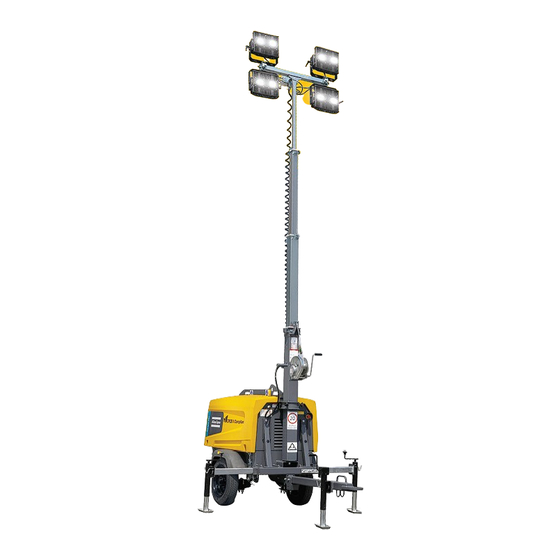
Main parts The light tower is provided with an undercarriage (frame, axle and towbar) and 4 LED floodlights of 350 W each. The light tower is useful for construction sites where neither electricity nor lighting is available. - 23 -... - Page 22 Reference Name Beam Battery Control Panel Drawbar Door Engine Emergency stop Exhaust Frame Fuel filler cap Fuel filter secondary Fuel filter primary Fuel tank Lamp Lifting Jack Mast Radiator Roof Undercarriage Winch - 24 -...
-
Page 23: Electrical Drawings
ELECTRICAL DRAWINGS Circuit Diagram - 9095 9700 74-01 ENGIINE SIDE CONNECTOR Legend 1 Wire size : Colour code : a = 1 mm 0 = black b = 1.5mm 1 = brown c = 2.5mm 2 = red d = 4 mm 3 = orange e = 6 mm 4 = yellow... - Page 24 9095 9700 74-02 CONNECTOR X1' TYPE: 770029-1 ARTICLE NO: 1088 0021 73 CRIMPS PART NO: 770008-3 PIN J1 CONTROLLER EMS324 X2:G1 35 Amp DC - I/P SUPPLY 2 Amp DC SUPPLY DC + I/P SUPPLY X2:P1 X2:P2 FUEL SOLENOID X2:P2 CRANK X2:E1 10 Amp...
- Page 25 9095 9700 74-03 Legend 1 Wire size : Colour code : a = 1 mm 0 = black b = 1.5mm 1 = brown c = 2.5mm 2 = red d = 4 mm 3 = orange e = 6 mm 4 = yellow f = 10 mm 5 = green...
- Page 26 9095 9700 74-04 - 28 -...
- Page 27 9097 4651 01 - Wiring harness - 29 -...
-
Page 28: Dimension Drawing - 9097 2992 13_01
Dimension drawing - 9097 2992 13_01 Type Machine HiLight V5+ Commercial Variant Max. permissible weight on towing eye 26 Kg Max.permissible weight on axle 1000 Kg Max. speed limit 20 Km/hr Net weight dry (Std. Machine) 664 Kg Net weight wet (Std. Machine) 764 Kg 1265 [49,819] 740 [29,1]... - Page 29 9097 2992 13_02 1175 [46,2] Fuel tank drain Engine oil drain LED Lamp Bottom View R638 [R25,1] R638 [R25,1] Level Indicator 62 [ 2,4] Towing eye 580 [22,8] 264 [10,4] Reflector SILENCER EXHAUST 2648 [104,3] 699 [27,5] 1572 [61,9] 920 [36,2] 1109 [43,7] Open Door Condition DATA PLATE...
- Page 30 9097 2992 13_03 Isometric View 2038 [80,230] 1183 [46,563] 1109 [43,662] 1900 [74,816] Overall Dimension for Transportation - 32 -...
-
Page 31: Engine Dimensional Drawing
Engine dimensional drawing Reference Dimension (mm) 269.2 242.5 515.5 169.5 351.5 484.5 - 33 -... -
Page 32: Operating Instructions
Operating instructions LIGHT TOWER OPERATION c Verify that all wheel lugs are in place Read the instruction manual Electric shock hazard. and tightened. Do not tow the trailer if carefully before using the light Contact with overhead electrical a wheel lug is missing or is loose. tower. -
Page 33: During Towing
e Raise, rotate, and lock the front jack 6. Move the tow vehicle away from the in the up position. trailer. Verify approved safety chains are attached properly to both the trailer and tow vehicle. During towing • Do not tow the trailer with any people, parts, supplies, or additional equipment attached to it or loaded onto it. - Page 34 Light fixture wiring - 36 -...
-
Page 35: Lifting
Lifting The light tower may be lifted by means of a hoist ring or through forklift slots on the lifting beam. Prior to lifting • Ensure that the mast is in the lowest position. • Return levelling jacks and outriggers to the travel position, and ensure they are all secured in place with their locking pins. -
Page 36: Deployment
DEPLOYMENT Levelling the trailer 6. Locate the outrigger on either side of the • The lights can be positioned trailer. Pull the outrigger locking pin without tools. Prior to raising and extending the light (not the jack locking pin) and pull the •To aim the lights, loosen the knob on tower mast, the trailer must be level and outrigger outward, away from the... - Page 37 Electric shock hazard. Contact with overhead electrical power lines will cause serious injury or death. Do not position light tower under power lines. 2. To raise the tower, follow these instructions: a Remove the horizontal-lock pin from the transport cradle. b Rotate the handle of the drawbar-mounted winch to tighten the cable and raise the light tower mast.
-
Page 38: Lowering The Tower
Lowering the tower Before moving or storing the light tower, lower the mast and lock it in place. To lower the tower, follow these instructions. 1. Turn off the tower lights and the engine. 2. Rotate the mast: a Loosen the rotation-lock knob. b Use the handle on the mast to rotate the mast until the mast- mounted winch is on the same side of the mast as the trailer tow hitch. -
Page 39: Control Panel
CONTROL PANEL Refer to engine operating instructions before starting the light tower. The light tower control panel comprises of: • Circuit breakers for protecting the light tower from over charge. • An electrical receptacle for powering external equipment (Option) • Controller to track engine use starting and stopping the engine. For electrical receptacle option- Do not overload the Reference Name receptacle with sockets. -
Page 40: Operation
Operation AC Frequency otherwise it jumps to Ready state at the end of 30 seconds. b Manual Start: In response to the front panel push button the unit performs a fully sequenced engine start. c Auto Start: In response to a digital input the unit performs a fully AC Volts Display sequenced engine start. - Page 41 DG Battery Voltage Display Engine RPM Display Service Due Warning Display If any of the alternator or engine Speed Sensing measurements move outside operational The unit obtains the speed information limits the unit deactivates the Fuel Control from the Generator AC output and shows Output to shut down the engine, if required the AC frequency and the Engine RPM on and display the respective Error Code on...
- Page 42 Shut Down To shut down the engine, simply turn off the key switch or Press the Manual Stop Button or remove the Auto Start input (depending on the application). The unit will deactivate the Fuel Control Output causing the engine to shut down. If the unit still sees Oil pressure and/or AC Frequency, 30 seconds after deactivating the fuel output, it will raise a Failed to Stop...
-
Page 43: Floodlight Lux Level - Hilight V5
Floodlight lux level - HiLight V5+ Lamps Rotation angle Inclination angle 70° -80° Case Angle Lamp 1 Lamp 2 Lamp 3 Lamp 4 Inclination Rotation Inclination Rotation Inclination 80-70 80-70 80-70 80-70 -180 Rotation Inclination Rotation - 45 -... - Page 44 Case 1 Case 2 Average Lux: 24 Average Lux: 23 - 46 -...
- Page 45 Case 3 Case 4 Average Lux: 21 Average Lux: 32 Lux level: - 47 -...
-
Page 46: Maintenance
The order number of the Service Pack are The order numbers of the Service kits are listed in the Atlas Copco Parts List (ASL). listed in the Atlas Copco Parts List (ASL). Contact Atlas Copco. -
Page 47: Maintenance Schedule
4153 1367 87 For the most important sub-assemblies, Atlas Copco has developed service kits that combine all wear parts. These service kits offer you the benefits of genuine parts, save on administration costs and are offered at reduces price, compared to the loose components. Refer to the parts list for more information on the contents of the service kit. - Page 48 Replace fuel pre-filter Replace fuelfilter Check rubber flexible Check emergency stop Replace air filter element Inspection by Atlas Copco service technician Inspect starter motor Inspect main alternator Check battery charging alternator for battery charging Check engine protective devices Jack / support lubrication...
- Page 49 Maintenance schedule for engine Maintenance Schedule (hours) Notes Every 50 Every 250 Every 500 Every 5000 Every 10000 hours hours / 3 hours hours hours months Clean the head and cylinder fins Clean the fuel injector Check the air cleaner for level of oil Check the valve/rocker arm clearance Check the injector setting Replace the Air filter...
- Page 50 Notes: 1. More frequently when operating in a dusty environment. 2. HiLight V5+ - 3.5 lit 3. After a days work. 4. Gummed or clogged filters means fuel starvation and reduced engine performance. 5. See section "Before starting". 6. Replace all rubber flexible each 3 years. 7.
-
Page 51: Maintenance Activities
MAINTENANCE ACTIVITIES Daily inspection Lamp unit replacement Replacement parts For replacement parts, refer to the parts When the light tower is in regular use, the In case the LED does not glow after overall manual. following items should be checked daily: wiring checks and replacement, the LED lamp unit has to be replaced. - Page 52 Transport mode • Horizontal position Tilting • Release the safety screw (A). • Rotate the lamps as per your desired position. • Refit safety screw. - 54 -...
-
Page 53: Battery Care
BATTERY CARE introduced into the battery. When charging batteries, each cell must be Before handling batteries, read open, i.e. plugs and/or cover removed. Always pour the sulphuric acid the relevant safety precautions carefully into the distilled water; Use a commercial automatic and act accordingly. -
Page 54: Axle Maintenance
AXLE MAINTENANCE Safety precautions Re-adjust the axle hub bearing axial Wheel bolt tightening torque clearance: • Welding or drilling on shaft tube is not Thread Hexagon Tightening torque • Remove the wheels and wheel covers. allowed. Size square width • Remove the slotted nut cotter pin. •... -
Page 55: Engine Maintenance
Engine maintenance Priming instructions Do not loosen the fuel lines at the detailed servicing fuel manifold. The fittings may Fuel leaked or spilled onto hot procedure, please refer to the be damaged and/or a loss of surfaces or electrical engine maintenance manual. priming pressure may occur components can cause a fire. -
Page 56: Oil Refilling
Oil refilling PRESCRIBED LUBRICANT Abbreviations reference It is strongly recommended to use AGIP Society of Automotive SUPER DIESEL MULTIGRADE 15W40 Engineers 10 5 oil. The oil capacity for the engine is 1.5 SAE 10W-30** American Petroleum Institute litres. The specifications of the prescribed SAE 10W-40** lubricant are as mentioned below: SAE 10W-60**... - Page 57 • Never operate the engine with too much or too little lubricant. Too much lubricant can raise the rpm abnormally and too little can cause excessive wear and burnout of components. • Always use the correct lube oil as per your application.
-
Page 58: Fuel Refilling
Fuel refilling PRESCRIBED FUEL FUELS FOR LOW TEMPERATURE BIODIESEL FUELS APPLICATIONS best results clean, fresh, Biodiesel containing less than 20% methyl commercial-grade diesel fuel. ester (B20) can be used as fuel for Kohler In case the unit has to be run at following fuels are best suited for the KDW702. -
Page 59: Troubleshooting
Troubleshooting ENGINE TROUBLESHOOTING Sr.No. Description Possible causes Troubleshooting Check points Engine does not start Check battery voltage and charge health. Check battery cable connections. Check that the start circuit is as per electrical drawing (e.g key switch, start relay, connector connections etc.) Check the supply at starter motor while cranking it (supply should be Fault in Electrical 12VDC). - Page 60 Mechanical component Check the governor linkage adjustment and ensure that it is free to malfunction or damage slide. Check if the cylinder head gasket is damaged and replace if necessary. Engine starts but stops Fault in Electrical If overloaded, stop the engine. Allow the engine to cool. Check all system connections for continuity and avoid running the engine overloaded.
- Page 61 Engine does not stop Fault in Electrical Check fuel solenoid circuit. system Check if the fuel solenoid de-energizes after turning the key to the OFF position. Check if fuel solenoid is working correctly. Engine does not accelerate Fault in Electrical If overloaded, stop the engine.
- Page 62 Check the cylinder for scores. Call Atlas Copco Service Technician for further assistance. Check if the piston rings are worn out or jammed. Call Atlas Copco Service Technician for further assistance. Check the valve guides fro wear or damage. Call Atlas Copco Service Technician for further assistance.
- Page 63 Check the cylinder for scores. Call Atlas Copco Service Technician for further assistance. Check if the piston rings are worn out or jammed. Call Atlas Copco Service Technician for further assistance. Check the valve guides fro wear or damage. Call Atlas Copco Service Technician for further assistance.
- Page 64 Check the cylinder for scores. Call Atlas Copco Service Technician for further assistance. Check if the piston rings are worn out or jammed. Call Atlas Copco Service Technician for further assistance. Check the valve guides fro wear or damage. Call Atlas Copco Service Technician for further assistance.
-
Page 65: Light Tower Troubleshooting
LIGHT TOWER TROUBLESHOOTING Sr.No. Description Possible causes Troubleshooting Check points Check alternator voltage at alternator output connector. Check for loose connections and fasten connectors if necessary. Check panel circuit as per drawing. Fault in Electrical Check that selector switch is on position '1'. system Lamp does not ON Check wire connections and supply (230VAC) to the junction box... -
Page 66: Technical Specifications
Technical specifications GENERAL TORQUE VALUES For hexagon screws and nuts with strength grade 12.9 The following tables list the recommended torques applied for general applications at assembly of the light tower. Thread size Torque value (Nm / lbf.ft) Thread size Torque value (Nm / lbf.ft) 15 (11.07) 9 (6.64) -
Page 67: Reference Conditions 1) 4)
REFERENCE CONDITIONS 1) 4) Designation Unit Hilight V5+ Rated frequency Rated speed 1500 Generator service duty Absolute inlet pressure Relative air humidity Air inlet temperature °C LIMITATION 2) Designation Unit Hilight V5+ Maximum ambient temperature °C Altitude capability 1000 Relative air humidity maximum Minimum starting temperature unaided °C Minimum starting temperature aided... -
Page 68: Performance Data 2) 3) 5)
PERFORMANCE DATA 2) 3) 5) Designation Unit Hilight V5+ Rated active power (PRP) 1ph Rated power factor (lagging) 1phase cos f 1.00 Rated apparent power 1ph Rated voltage 1ph. line to line Rated current 1ph. 21.7 Fuel consumption at no load (0%) kg/h 0.435 Fuel consumption at 1 lamp on... -
Page 69: Application Data
APPLICATION DATA Designation Unit Hilight V5+ Mode of operation Site land use Operation single Start-up and control mode manual Start-up time unspecified Mobility/ Config. acc. to ISO 8528-1:1993 mobile Mounting fully resilient Climatic exposure open air Status of neutral earthed Auxiliary power Socket size - 71 -... -
Page 70: Design Data 4)
DESIGN DATA 4) Alternator Designation Unit Hilight V5+ EN 60034-1 Standard IEC 60034-1 Make Meccalte Model LT3N Rated output, class H temp. rise Degree of protection - 72 -... -
Page 71: Engine
Engine Designation Unit Hilight V5+ Standard ISO 3046 Make KOHLER Model KDW702 Rated output 5.1KW@1500rpm Production tolerance ±5 ETHYLENE GLYCOL Coolant BASED ANTI-FREEZE Combustion system Direct injection Aspiration Naturally aspirated Number of cylinders Swept volume 0.686 Speed governing Mechanical Capacity of oil sump Electrical system LED LOAD Each LED power watt (PRP) 1ph... -
Page 72: Power Circuit
Power circuit Circuit breaker Designation Unit Hilight V5+ Number of poles Thermal release as per UL489 Magnetic release as per UL489 Fault current protection Residual current release Dimension and weight Overall Dimensions for transportation (Approx) - Length - Width - Height Overall Dimensions ready to operation (Approx) - Length - Width... - Page 73 Notes: 1. Reference conditions for engine performance to ISO 3046-1 / GB/T 6072.1 2. See derating diagram or consult the factory for other conditions 3. At reference conditions unless otherwise stated 4. Rating Definition (ISO 8528-1 / GB/T 2820.1): Limited Time Power is the maximum electrical power which a generating set is capable of delivering (at variable load), in the event of a utility power failure (for up to 500 hours per year of which a maximum of 300 hours is continuous running).
-
Page 74: Options
Options - 76 -... -
Page 75: Disposal
Do not drain into the sewage unavoidable rates of not recyclable system or surface water. materials. Your Atlas Copco light tower consists for the most part of metallic materials, that can be remelted in steelworks and smelting works and that is therefore almost infinite recyclable. -
Page 76: Maintenance Log
Maintenance log Light tower Customer............................Serial number............................... Service hours Maintenance action Date By initials - 78 -... -
Page 77: Maintenance Log
Maintenance log Light tower Customer............................Serial number............................... Service hours Maintenance action Date By initials - 79 -... -
Page 78: Maintenance Log
Maintenance log Light tower Customer............................Serial number............................... Service hours Maintenance action Date By initials - 80 -...
Need help?
Do you have a question about the HiLight V5+ PNE and is the answer not in the manual?
Questions and answers