Advertisement
Advertisement
Table of Contents

Related Manuals for Radioddity CB-900 PRO


Summary of Contents for Radioddity CB-900 PRO
- Page 1 CB-900 PRO CB RADIO...
-
Page 2: Table Of Contents
CONTENTS 1.STANDARD ACCESSORIES .............1 ...............1 3.INSTALLATION ..................1 4.GETTING ACQUAINTED ..............5 5.HOW TO USE YOUR RADIO ............7 6.SLIDE SWITCHES ................8 7.FUNCTION MENU ................9 8.SPECIFICATIONS ................11... -
Page 3: Standard Accessories
Adhesive Case Radio Microphone Mounting Bracket Microphone Hanger Protectors DC Power Screws for Pads for Adjusting Spare Fuses Self-tapping Pads Cable bracket bracket screws Screws (3A,250V) External Speaker Choose the most appropriate location from a simple and practical point of view. If installed in a vehicle, care should be taken to ensure your radio does not obstruct the driver or passengers. -
Page 4: Installation
1. Plug microphone connector into the microphone jack. 2. Tighten the retaining ring on the microphone connector by hand. ANTENNA INSTALLATION Before using this radio, please install an efficient and resonant antenna. Using an antenna that is correctly installed and tuned will enable excellent communication performance. - Page 5 1. Connect the positive (red) power cable to the + terminal of the battery. 2. Connect the negative (black) power cable to the - terminal of the battery. 3. Connect the DC power cable to the transceiver's power supply connector. electrical systems.
- Page 6 INSTALL MICROPHONE HANGER Choose a location which will not interfere with the driver. Use the supplied self-tapping screws and pads to install the hanger. INSTALL EXTERNAL SPEAKER (Optional) If using an external speaker, please choose an 8 ohm speaker with a 3.5mm mono (double cable) TS type plug.
-
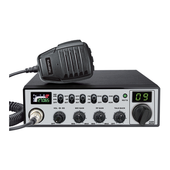
Page 7: Getting Acquainted
4. GETTING ACQUAINTED Front Panel No. Functions TFT LCD Channel Display: CH and Scrolling Frequency Display 4-Pin Microphone Connector Squelch Control Microphone Gain Control RF Gain Control... - Page 8 Rear Panel Functions Antenna Connector Public Address Speaker Jack External Speaker Jack Power Jack Microphone Connector Microphone cable...
-
Page 9: How To Use Your Radio
5. HOW TO USE YOUR RADIO Power OFF/ON 1. Turn the VOL the beep function is enabled). The LED display will show a channel number. 2. Turn the VOL knob anti-clockwise, until hear Ka Ta, the radio is powered off. Volume Control Turn the VOL knob clockwise to increase the Volume, Turn it anti-clockwise to decrease the Volume. -
Page 10: Slide Switches
UP / DN Buttons On Microphone In normal operation, press UP / DN buttons on the microphone to change the channel. UP to increase, and DN to decrease the channel. PUSH knob for about 3 seconds to activate this mode), the UP or DN buttons allows to select the mune to be set. -
Page 11: Function Menu
Select the CB mode Mode Select the Public Address (PA) mode Select the Frequency Modulation (FM) mode Modulation Mode Select the Amplitude Modulation (AM) mode To access Instant channel 9 Instant Channel Return to the original channel selected 7. FUNCTION MENU 1. - Page 12 Squelch (default) Scan type setting Scan Type Time ON : turn on ECHO OFF : turn off (default) 1 ~ 32 ECHO Volume Default : 28 setting 1 ~ 32 ECHO Delay Default : 28 ON : turn on ALERT function ALERT function setting WX Alert OFF : turn off ALERT function (default)
-
Page 13: Specifications
8. SPECIFICATION GENERAL Modulation Mode Frequency Range 26.965-27.405MHz 162.400-162.550MHz Frequency Tolerance ±5.0ppm Input Voltage Dimensions 1.02kg to +50 Transmit Current Drain Receive Squelched 0.3A 0.7A Antenna Connector TRANSMITTER Transmission interference Frequency Response 300-3000Hz Modulated signal distortion inferior to 5% 50 ohms RECEIVER Sensitivity Image Rejection... - Page 14 SAIN3 LLC Address: 36 Berkley Drive Newark Delaware 19702 United States support@radioddity.com...
Need help?
Do you have a question about the CB-900 PRO and is the answer not in the manual?
Questions and answers