
Related Manuals for ErGear EGESD25B


Summary of Contents for ErGear EGESD25B
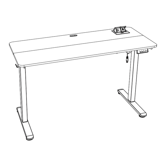
- Page 1 Electric Standing Desk Instruction Manual EGESD25B / EGESD25WN EGESD26B / EGESD26WN Rev00(A) support@ergear.com 1-800-651-9525 (US/CA) Mon–Fri, 8am–8pm (CST) 44-808-196-3875 (UK) Mon–Fri, 2pm–10pm (UTC) https://ergear.com WWW.
-
Page 3: Specifications
Tools Needed (Not lncluded) Drill Phillips Screwdriver Specifications Height Adjustment Range RATED 28.4”–46.5” (72-118cm) Power Input Max. Speed Operating Noise Max. Load 100V-240V 21mm/s ≤52dB 176 lbs / 80 kg Step 1 Supplied Parts and Hardware Bolt Bolt Right Crossbar Left Crossbar Right Desk Leg M6 x 12mm... - Page 4 Step 3 Supplied Parts and Hardware x 11 Bolt Screw Large Allen Wrench Fixed Rod Middle Crossbar M6 x 42mm ST4.8 X 12mm 3/16” (5mm) Step 4 Supplied Parts and Hardware Bolt Transmission Rod Wrench M4 x 3.5mm Step 5 Supplied Parts and Hardware Screw Controller...
- Page 5 Step 7 Supplied Parts and Hardware AC Adapter Cable Clip Step 8 Supplied Parts and Hardware Screw Power Outlet Box M6 x 35mm Step 9 Supplied Parts and Hardware Cable Hole Cover...
- Page 6 Assembling the Leg Sections Step 1 Attach the crossbars. 01 01 01 01 01 01 To install correctly, align these small round protrusions with the round holes on the crossbars. Attach the side plates.
- Page 7 Screw in the bolts, but do not fully tighten them until all four bolts are in place. Slightly loosen four pre-installed bolts on the crossbars. 01 01...
- Page 8 Assembling the Desktop Step 2 Connect the desktop panels using the wood dowel pins. Secure the desktop panels with the connectors. Phillips Drill Screwdriver (not included) (not included) You can use a drill (with suitable torque and speed) or a Phillips screwdriver.
- Page 9 Attaching the Frame to the Desktop Step 3 Place the vertical support bar and middle crossbar on the desktop, and pay attention to their positions. Also, make sure their screw holes are aligned with large screw hole on the desktop. Loosely thread the bolt through the middle crossbar and vertical support bar, then into the desktop.
- Page 10 Slide two leg sections onto the middle crossbar. 01 01 Adjust two leg sections. Ensure the screw holes are aligned.
- Page 11 Fully tighten four pre-installed bolts on the crossbars securing the frame. Secure the frame to the desktop. 01 01...
- Page 12 Attaching the Transmission Rod Step 4 Fig 1 Left Leg Left Leg Left Leg Left Leg 10 10 Turn clockwise Turn clockwise Turn clockwise Turn clockwise Fig 2 Left Leg Left Leg Left Leg Left Leg 10 10 10 10 Turn Turn Turn...
- Page 13 Use the set screws to secure the rod coupler. Phillips Screwdriver (not included) Attaching the controller and the Step 5 storage hooks 12 12 11 11 11 11...
- Page 14 Attaching the Cable Management Tray Step 6 Fold the cable management tray [13] along the dashed line. 13 13 You can use a drill (with Phillips suitable torque and speed) Drill Screwdriver or a Phillips screwdriver. (not included) (not included) 13 13...
-
Page 15: Connecting The Cables
Connecting the Cables Step 7 15 15 15 15 11 11 11 11 Motor Motor 14 14 Cable Cable Attaching the Power Outlet Step 8 Press the button to open the cover. Separate the power outlet by loosening the pre-installed bolts, and save them for later use. Phillips Screwdriver (not included) - Page 16 Secure the power outlet box to the desktop. 16 16 16 16 Secure the other part to the power outlet box. Pre-installed Pre-installed bolt bolt...
-
Page 17: Using The Controller
Installing the Cable Hole Cover Step 9 17 17 Using the Controller Note: After initial power-on, the screen will show the current height. If the displayed height doesn't match the actual height or if the desk legs are unequal, please follow the reset instructions. Reset 1. - Page 18 Save Current Height Setting Press and hold the button for 3 seconds. The screen will show ‘S-1,’ and the current height will be saved to that button. Short-press the button, and the desk will move to the height that was previously set for that button. Press any button to stop the desk.
- Page 19 Protection Mode Error Codes Overheating Protection: When the motor has been working continuously for too long, it will stop operating to prevent overheating. Wait 18 minutes for the motor to cool down before making any further height adjustment. Reset Warning: Continue to complete reset. Overloading Protection: Max load exceeded.
- Page 20 Thank you for choosing this ErGear product. At ErGear we strive to provide you with the best quality products and services in the industry. Should you have any issues, please don't hesitate to contact us. 1-800-651-9525 (US/CA) Mon–Fri, 8am–8pm (CST) 44-808-196-3875 (UK) Mon–Fri, 2pm–10pm (UTC)
Need help?
Do you have a question about the EGESD25B and is the answer not in the manual?
Questions and answers