Advertisement
Quick Links
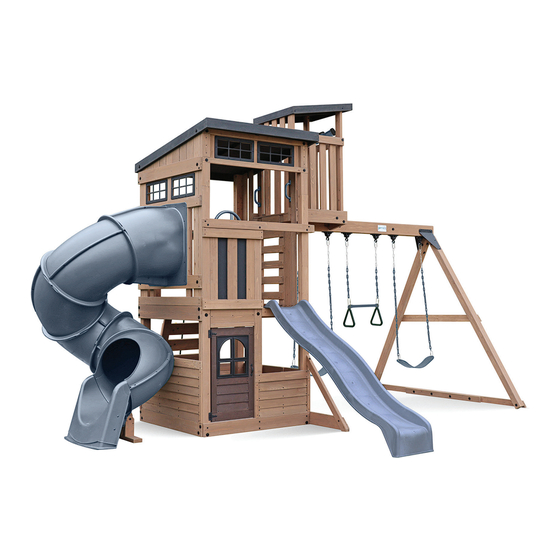
Skyline Lookout Outdoor Playset
IMPORTANT, RETAIN FOR FUTURE REFERENCE: READ CAREFULLY
10-14 Hrs
Two Person
Assembly
Adult Assembly Required
WARNING
T
o reduce the risk of serious injury or death, you must read and follow these instructions.
Keep and follow these instructions often and give them to any future owner of the play
system. Manufacturer contact information provided on this page.
OBSTACLE FREE SAFETY ZONE: 28' 4-5/16" x 27" 4-1/4" (8.64m x 8.34m), area requires Protective Surfacing, see page 10
MAXIMUM VERTICAL FALL HEIGHT: 7.1' (2.16m)
CAPACITY: 10 users Maximum, Ages 3 to 10, Weight Limit 110 lbs (49.9 kg) per child
RESIDENTIAL HOME USE ONLY. Not intended for public areas such as schools, churches, nurseries, day cares or parks.
51-1130
05/22/2024
playsets
playsets
Copyright © 2023 Gorilla Playsets
All Rights Reserved
166 Etowah Industrial Court
Canton, GA 30114
1-800-882-0272
www.gorillaplaysets.com
Made in China
1
™
™
Model: GM52000
ITM. / ART. 1740603
(BOXES: 1, 2, 3
8.64m
28'-4 5/16"
4.97m
16'-3 5/8"
5.37m
17'-7 3/8"
Height:
11' 3-1/2" (3.44m)
22'-3 5/16"
www.gorillaplaysets.com/customer-care
www.gorillaplaysets.com/customer-care
& Slide)
Height = 11' 3-1/2"
8.34m
3.59m
27'-4 1/4"
11'-9 3/8"
6.79m
Advertisement

Related Manuals for Gorilla Playsets Skyline GM52000


Summary of Contents for Gorilla Playsets Skyline GM52000
- Page 1 ITM. / ART. 1740603 (BOXES: 1, 2, 3 & Slide) Skyline Lookout Outdoor Playset IMPORTANT, RETAIN FOR FUTURE REFERENCE: READ CAREFULLY Copyright © 2023 Gorilla Playsets 10-14 Hrs All Rights Reserved 166 Etowah Industrial Court Height = 11' 3-1/2" Canton, GA 30114 8.64m...
- Page 2 Please inspect and inventory all parts immediately upon accepting delivery. Use the inventory pages in the manual to make sure you have received all necessary parts. The quickest method to get any parts that are missing or damaged is to use our “Quick Response Center”...
- Page 3 This decision is subject to verification of the defect, which, at Gorilla’s discretion, may be accomplished by submitting photographs or by delivery of the defective part to Gorilla Playsets • 166 Etowah Industrial Ct. • Canton, GA 30114 • 1-800-882-0272 Monday to Friday 9AM-5PM EST. Any warranty claim must include proof of purchase, including the date of purchase.
- Page 4 IMPORTANT SAFETY GUIDELINES This product is recommended for use by children ages 3-10. This product is intended for residential use only and not intended for use in any public setting. A safety surface such as mulch or recycled tire should be used under the play set to prevent injury from falls.
- Page 5 WARRANTY REGISTRATION NAME: Gorilla Playsets manufactures ™ 3 EASY WAYS TO REGISTER the finest quality products that Mail this completed form to: are designed for outstanding Fax this completed form to: Gorilla Playsets OPTION 1 strength and durability. We back...
- Page 6 THIS PAGE INTENTIONALLY LEFT BLANK www.gorillaplaysets.com/customer-care...
- Page 7 IMPORTANT – PLEASE READ Congratulations! You have just purchase one of the finest residential wooden swing sets available today. As with any wooden product that spends its entire life outside, in varying elements, it is important to know what to expect with your new swing set so that your family can enjoy it for many years.
- Page 8 Safety and Maintenance Tips for Your New Play Set: NOTE: Your children’s safety is our #1 concern. Observing the following statements and warnings reduces the likelihood of serious or fatal injury. Please review these safety rules regularly with your children. •...
- Page 9 Safety and Maintenance Tips for Your New Play Set: (continued) Playgrounds should be inspected on a regular basis. If any of the following conditions are noted, they should be removed, corrected, or repaired immediately to prevent injuries. • Hardware that is loose, worn or that has protrusions or projections. •...
- Page 10 PLAYGROUND SURFACING MATERIALS SECTION 4 OF THE CONSUMER PRODUCT SAFETY COMMISSION’S OUTDOOR HOME PLAYGROUND SAFETY HANDBOOK Select Protective Surfacing One of the most important things you can do to reduce the likelihood of serious head injuries is to install shock-absorbing protective surfacing under and around your play equipment.
- Page 11 Play Set Surfacing Recommendations: Below are some of the recommendations that the U.S. Consumer Product Safety Commission (CPSC) offers from its Handbook for Public Playground Safety. The guide can be downloaded in full at www.cpsc.gov/cpscpub/pubs/325.pdf 1. Protective Surfacing - Since almost 60% of all injuries are caused by falls to the ground, protective surfacing under and around all playground equipment is the most critical safety factor on playgrounds.
- Page 12 2. Fall Zones - A fall zone, covered with a protective surfacing material, is essential under and around equipment where a child might fall. This area should be free of other equipment and obstacles onto which a child might fall. Stationary climbing equipment and slides should have a fall zone extending a Minimum of 6’...
- Page 13 General Info to Review Before Installation • Depending on your experience, assembly of the playset can take as little as 6 hours up to 24 hours, depending on size, after inventory of parts; therefore, we recommend you set aside a full two days for assembly. •...
- Page 14 This page is a list of definitions and explanations used throughout our instructions to aid you in the assembly of your play set. Offset Holes- Throughout the installation procedures we will refer to parts with offset holes. This refers to the orientation of the holes on the board. An offset hole is one that is closer to one side than it is the other or in other words, it is not centered on the board.
- Page 15 Keys to Assembly Success Tools Required • Tape Measure • #2 Phillips bit or • Open End Wrench • 8’ Step Ladder x 2 • Carpenters Level Screwdriver (7/16", 1/2”, 9/16" & 5/8”) • Safety Glasses • Carpenters Square • Ratchet with extension •...
- Page 16 . . Gorilla Playsets 166 Etowah Industrial Court Canton, GA.
- Page 17 Part Identification ( Dimensions are approximate and are shown to assist in the identification of parts for assembly. Actual dimensions may be smaller or larger. 4pc. (P001) - Long Post 2336.8mm (92") (G50229-P001) 4pc. (P002) - Lower Post 1092.2mm (43") FSC (G50229-P002) 2pc.
- Page 18 Part Identification ( Dimensions are approximate and are shown to assist in the identification of parts for assembly. Actual dimensions may be smaller or larger. 3pc. (P023) - Top Siding 1141.4mm (44-15/16") FSC 3pc. (P024) - Transom Upright 295mm (11-5/8") FSC (G50229-P023) (G50229-P024) 8pc.
- Page 19 Part Identification ( Dimensions are approximate and are shown to assist in the identification of parts for assembly. Actual dimensions may be smaller or larger. 1pc. (P044) - Turbo SL Center Post 227.2mm (8-15/16") FSC 2pc. (P045) - Turbo SL Side Post 198.1mm (7-13/16") FSC (G50229-P044) (G50229-P045) 1pc.
- Page 20 Part Identification ( Dimensions are approximate and are shown to assist in the identification of parts for assembly. Actual dimensions may be smaller or larger. 5pc. (P066) - Sky Loft Step 457.2mm (18") FSC 1pc. (P067) - Short Sky Loft Post LT 1106.3mm (43-9/16") (G50229-P066) (G50229-P067) 1pc.
- Page 21 Part Identification ( Dimensions are approximate and are shown to assist in the identification of parts for assembly. Actual dimensions may be smaller or larger. 1pc. (P098) - Mid Chalk Wall Upright 838.2mm (33") FSC 2pc. (P099) - Gusset 304.8mm (12") FSC (G50229-P098) (G50229-P099) 1pc.
- Page 22 Hardware Identification ( Dimensions are approximate and are shown to assist in the identification of parts for assembly. Actual dimensions may be smaller or larger. #8 x 1-1/8" 68pc. Wood Screw (Y06018-514) 1pc. #2 x 2" Robertson Driver (Y00400-005) #8 x 1-1/2" 326pc.
- Page 23 Hardware Identification ( Dimensions are approximate and are shown to assist in the identification of parts for assembly. Actual dimensions may be smaller or larger. 4pc. Hex Bolt 1/4 x 4-1/2" - (Y07718-242) 10pc. Hex Bolt 1/4 x 4-1/4" - (Y07718-241) 5/16 x 2"...
- Page 24 ( Dimensions are app_ r oxim�te and are shown to assist in the identification of parts for ) assembly. Actual dimensions may be smaller or larger. Part Identification 1 pc. Plastic Dormer Window - Black 1 pc. Square Window Pane - Black (4pk) 1 pc.
- Page 25 www.gorillaplaysets.com/customer-care...
- Page 26 ( Dimensions are app_ r oxim�te and are shown to assist in the identification of parts for ) assembly. Actual dimensions may be smaller or larger. Part Identification PICTURE DESCRIPTION PICTURE PICTURE DESCRIPTION 1 pc. Plastic Dormer Window - Black 1 pc.
- Page 27 ( Dimensions are app_ r oxim�te and are shown to assist in the identification of parts for ) assembly. Actual dimensions may be smaller or larger. 1733Z Wrench 1381Z Square Drive Square lock nut QTY: 1 QTY: 18 QTY: 45 Part Identification 1 pc.
- Page 28 Step 1: Inventory Parts - Read This Before Starting Assembly STOP STOP STOP STOP This is the time for you to inventory all your hardware, wood and accessories, referencing the parts identification sheets. This will assist you with your assembly. •...
- Page 29 Step 2: Front Post Assemblies A: Lay one (P001) Long Post on a flat surface, taking note of hole orientation. Place one (P002) Lower Post on (P001) Long Post making sure that it’s flush to the end with the bolt hole and the holes are aligned. Attach Posts Step 1 - Front Post Assembly with 10 #8 x 2-1/4”...
- Page 30 Step 3: Back Post Assemblies A: Lay one (P001) Long Post on a flat surface, taking note of hole orientation. Place one (P002) Lower Post on (P001) Long Post making sure that it’s flush to the end with the bolt hole and the holes are aligned. Attach Posts with 10 #8 x 2-1/4”...
- Page 31 Step 4: Front Wall Assembly Part 1 A: Place each Front Post Assembly so the 4” [101.6mm] opening is on the underside, then place one (P008) Ground across the bottom of the assembly, loosely attach using two 5/16 x 3” Hex Bolts (with 5/16” lock washer, 1/4-5/16”...
- Page 32 Step 4: Front Wall Assembly Part 2 F: Attach (P011) Mid Post to (P060) Front Floor Support with one 1/4 x 2-1/2” Hex Bolt (with 1/4” lock washer, 1/4-5/16” large washer and 1/4” t-nut) and (P020) Mid Front with one 1/4 x 2-1/4” Hex Bolt (with 1/4” lock washer, 1/4-5/16”...
- Page 33 Step 5: Back Wall Assembly A: Place Back Post Assemblies so the 4” [101.6mm] opening is on the underside, then place one (P008) Ground across the bottom of the assemblies so that each end is flush. Loosely attach using two 5/16 x 3” Hex Bolts (with 5/16”...
- Page 34 Step 6: Swing Wall Assembly Part 1 A: With at least one helper, stand the assemblies so the Front Wall Assembly is on the left and the Back Wall Assembly is on the right, making sure (P001) Long Posts are facing the outside. Place (P059) SW Ground along the bottom of the Wall Assemblies, the end with the sharper angle should be to the left.
- Page 35 Step 6: Swing Wall Assembly Part 2 Note: Pre-drill all pilot holes using a 1/8” drill bit before installing Lag Screw. D: At the left end of the (P059) SW Ground, position (P017) Diagonal behind SW Ground with the countersunk hole at the top.
- Page 36 Step 7: Turbo SL Wall Assembly sembly Note: Pre-drill all pilot holes using a 1/8” drill bit before installing Lag Screw. A: Place (P009) Side Ground along the bottom and install two 1/4 x 4” Hex Bolts (with 1/4” lock washer, 1/4-5/16” large washer and 1/4”...
- Page 37 Step 8: Install Gussets Note: Pre-drill all pilot holes using a 1/8” drill bit before installing Lag Screw. A: On each side of the SW Wall, position one (P099) Gusset as shown in F8.1, making sure it’s flush with the edge of the posts.
- Page 38 Step 9: Floor Assembly Part 1 A: On the Turbo SL Wall side, slide one (P007) Floor Board into the gaps, making sure that it’s tight to (P061) Floor End. Attach each end of the floor board to the Floor Supports using one #8 x 1-1/2” Wood Screw per side. Repeat to install a second (P007) Floor Board on the Swing Wall side.
- Page 39 Step 9: Floor Assembly Part 2 D: Evenly space the remaining seven (P007) Floor Boards and attach using six #8 x 1-1/2” Wood Screws per board. (F9.3) F9.3 #8 x 1-1/2” Wood Screw x 42 (P007) Floor Board Flush Wood Parts Hardware 42 x #8 x 1-1/2”...
- Page 40 Step 10: Large Roof Assembly Part 1 A: Stand (P050) Side Roof Joist LT and (P049) Side Roof Joist RT on their edges with the cut-outs to the inside, taking note of board placement and hole orientation. Place a (P051) F/B Roof Fascia across each end, making sure all corners are flush and pilot holes are to the top.
- Page 41 Step 10: Large Roof Assembly Part 2 E: Place 14 (P053) Roofing boards evenly spaced along the frame cut-outs as shown in F10.4 and attach using three #8 x 7/8” Truss Screws per board. (F10.4) #8 x 7/8” Truss Screw x42 F10.4 (P050) Roofing (P115)
- Page 42 Step 11: Install Large Roof A: With at least one helper, lift Large Roof up and over the frame assembly so the bolt holes in the roof frame line up with the posts and the longer overhang is at the front. Attach the Large Roof Assembly to the posts from the outside using four 1/4 x 4-1/2”...
- Page 43 Step 12: Install Siding Part 1 A: From outside the Front Wall Assembly, place one (P014) Trim on the (P008) Ground so that it’s flush with the left edge of (P011) Mid Post, then attach using three #8 x 1-1/2” Wood Screws. Place a second (P014) Trim on (P008) Ground so that it’s flush to the right outside edge of the Front Post Assembly.
- Page 44 Step 12: Install Siding Part 2 F: From outside the SW Wall Assembly, place one (P014) Trim on the (P059) SW Ground so they’re flush with the outside edges of the Posts. Attach to each Post Assembly using three #8 x 1-1/2” Wood Screws per side. (F12.3 and F12.4) G: Place a (P028) SW Mid Wall across the top of both (P014) Trims so the ends are flush.
- Page 45 Step 12: Install Siding Part 3 K: From outside the Back Wall Assembly, place one (P014) Trim on the (P008) Ground so they’re flush with the outside edges of the Posts. Attach to each Post Assembly using three #8 x 1-1/2” Wood Screws per side. (F12.5 and F12.6) L: Place a (P028) SW Mid Wall across the top of both (P014) Trims so the ends are flush.
- Page 46 Step 12: Install Siding Part 4 P: From outside the Turbo Wall Assembly, place one (P013) Turbo Trim Wall on the (P009) Side Ground so they’re flush with the outside edges of the Posts. Attach to each Post Assembly using three #8 x 1-1/2” Wood Screws per side.
- Page 47 Step 13: Install Uprights A: From inside the assembly, center five (P016) Uprights over the pilot holes in the Front Wall, Back Wall and SW Wall. Attach using four #8 x 1-1/8” Wood Screws per Upright. (F13.1) B: From inside the assembly, center two (P089) Long Uprights over the pilot holes and notches in the Turbo Wall. Attach using four #8 x 1-1/8”...
- Page 48 Step 14: Swing Beam Assembly Part 1 A: Attach six Swing Hangers to (P055) SW Beam using twelve 3/8 x 6” Hex Bolts (with two 3/8“ flat washers and 3/8” lock nut), making sure bolts are installed through the countersunk holes. (F14.1 and F14.2) Countersunk F14.1 3/8 x 6”...
- Page 49 Step 14: Swing Beam Assembly Part 2 B: At the locations shown in F14.4 install three 5/16 x 3-1/4” Hex Bolts (with 5/16” lock washer, 1/4-5/16” large washer and 5/16” t-nut). (F14.3 and F14.4) THESE BOLTS MUST BE INSTALLED TO HELP REDUCE CHECKING OF THE WOOD. F14.3 5/16 x 3-1/4”...
- Page 50 Step 15: Attach Triplate A: Position Triplate on (P033) SW Mount so bolt holes align and overhang is towards the outside. Attach using the outside holes with two 3/8 x 3-1/2” Carriage Bolts (with 3/8” large washer and 3/8”lock nut). (F15.1 and F15.2) F15.1 (P033)
- Page 51 Step 16: A Frame Assembly Part 1 A: Position two (P057) A-Frame Supports so the straight ends meet, taking note of the orientation. Tap four 5/16” t-nuts into the bolt holes. Flip (P057) A-Frame Supports over and place (P058) A-Frame Support Joiner centered over both supports so bolt holes are aligned and edges are flush.
- Page 52 Step 16: A Frame Assembly Part 2 C: Position one (P056) A-Frame Leg under each end of the A-Frame Support Assembly so holes are aligned, and T-Nuts are on top. The double bolt holes should be at the top end. Loosely attach A-Frame Support Assembly to both (P056) A-Frame Legs with two 1/4 x 4”...
- Page 53 Step 16: A Frame Assembly Part 3 E: Place a Post SW Beam Under Bracket so the holes align with the (P056) A-Frame Legs. Loosely attach with two 3/8 x 3-1/2” Carriage Bolts (with 3/8” large washer and 3/8” lock nut). (F16.6 and F16.7) F16.6 attach all bolts loosely (P056)
- Page 54 Step 16: A Frame Assembly Part 4 F: With two helpers position the Swing Beam end with the double holes between the Post SW Beam Plate Bracket - Left and Post SW Beam Plate Bracket - Right so holes align. Loosely attach with one 3/8 x 5-1/2” Hex Bolt (with 3/8”...
- Page 55 Step 17: Attach Swing End Part 1 A: Carefully lift the Swing Assembly and center on the Triplate. Loosely attach with one 3/8 x 8-3/4” Hex Bolt (with two 3/8” flat washers and 3/8” lock nut) and one 3/8 x 5-1/2” Hex Bolt (with 3/8” flat washer and 3/8” lock nut). F17.1 F17.2 3/8 x 8-3/4”...
- Page 56 Step 17: Attach Swing End Part 2 Note: Pre-drill all pilot holes using a 1/8” drill bit before installing Pan Screws. B: Attach (P117) A-Frame Mid Support to (P056) A-Frame Legs using two 5/16 x 3-3/4” Hex Bolts (with 5/16” lock washer, 5/16”...
- Page 57 Step 18: Attach Ground Stakes MOVE FORT TO FINAL LOCATION PRIOR TO STAKING. FINAL LOCATION MUST BE LEVEL GROUND WARNING! To prevent tipping and avoid potential injury, stakes must be driven fully into ground. Digging or driving stakes can be dangerous if you do not check first for underground wiring, cables or gas lines.
- Page 58 Step 19: Chalk Wall Assembly Part 1 A: From outside the assembly on the left side of the Front Wall, place one (P096) Chalk Wall Board so it’s tight under (P020) Mid Front and flush to the frame on both ends. Attach with four #8 x 1-3/4” Wood Screws. (F19.1 and F19.2) B: Place a second (P096) Chalk Wall Board so it lines up with the floor boards and is flush to the frame on both ends then attach with four #8 x 1-3/4”...
- Page 59 Step 19: Chalk Wall Assembly Part 2 C: From inside the assembly, place one (P097) Chalk Wall Upright on each side of the chalk wall opening so they are tight to the frame. Attach using four #8 x 1-1/8” Wood Screws per board. (F19.4, F19.5 and F19.6) D: Place (P098) Mid Chalk Wall Upright so it’s evenly spaced between the (P097) Chalk Wall Uprights and attach using four #8 x 1-1/8”...
- Page 60 Step 19: Chalk Wall Assembly Part 3 E: From inside the assembly, center one (P110) Chalk Frame A so it is flush with the top of (P096) Chalk Wall Board, attach with three #8 x 1-1/8” Wood Screws. (F19.7, F19.8 and F19.9) F: Insert Chalk Board behind (P110) Chalk Frame A so it’s centered and sitting on the cutout of the chalk frame.
- Page 61 Step 20: Rockwall Climber Assembly Part 1 A: Lay two (P036) Rock Rails side by side, flat, with the angled ends facing downward. (F20.1 and F20.2) B: Place (P037) Rock Bottom across the bottom ends and flush to the right of the (P036) Rock Rails with the large hole towards the bottom.
- Page 62 Step 20: Rockwall Climber Assembly Part 2 G: Place 2 Rocks on each (P038) Rock Board, alternating colors as desired. Attach using two 1/4 x 1-1/4” Hex Bolts (with 1/4” lock washer, 3/16” flat washer and 1/4” t-nut) per Rock. (F20.3, F20.4 and F20.5) Rock Black/Grey F20.3...
- Page 63 Step 20: Rockwall Climber Assembly Part 3 H: Flush to the inside end of (P059) SW Ground, position one (P039) Rock Wall Block as shown in F20.6 and F20.7. Attach loosely using one 5/16 x 2” Hex Bolt (with 5/16” lock washer, 1/4-5/16” large washer and 5/16” t-nut). Check that the edge of the block is flush to the edge of the board, then tighten bolt and install one #8 x 1-1/2”...
- Page 64 Step 21: Attach Rockwall Climber Assembly Part 1 A: Place Rock Wall Assembly so it’s centered in the opening on the Back Wall. (P037) Rock Bottom should be flush to the outside of (P059) SW Ground. Have a helper hold the Rock Wall in place, then attach (P037) Rock Bottom to (P039) Rock Wall Block using two #8 x 1-3/4”...
- Page 65 Step 21: Attach Rockwall Climber Assembly Part 2 WARNING! To prevent tipping and avoid potential injury, stakes must be driven fully into ground. Digging or driving stakes can be dangerous if you do not check first for underground wiring, cables or gas lines. D: Drive Anchor Stake into the ground at the location shown in F21.5 and F21.6 then attach with one #12 x 2”...
- Page 66 Step 22: Sky Loft Access Part 1 A: Lay two (P069) Sky Loft Access Sides so they are side by side with the cut outs facing up. Place four (P066) Sky Loft Steps into the cut outs without holes so they are flush to the edges of the access sides. Make sure Access Assembly is square and attach with four #8 x 1-1/2”...
- Page 67 Step 22: Sky Loft Access Part 2 C: From inside the assembly, position Sky Loft Access so it is centred between posts and the end with the pre- installed t-nuts is at the top and aligns with the bolt holes in (P033) SW Mount. Attach to (P033) SW Mount using two 5/16 x 3”...
- Page 68 Step 23: Sky Loft Assembly Part 1 A: Taking note of hole orientation, loosely attach one (P068) Sky Loft Post and one (P067) Short Sky Loft Post LT to a (P079) Sky Loft Base using two 1/4 x 4” Hex Bolts (with 1/4” lock washer, 1/4-5/16” large washer and 1/4” t-nut).
- Page 69 Step 23: Sky Loft Assembly Part 2 E: Stand the assemblies side by side with Posts to the inside, then loosely attach (P080) Sky Loft End to the lower holes of (P068) Sky Loft Posts using two 1/4 x 2-1/2” Hex Bolts (with 1/4” lock washer, 1/4-5/16” large washer and 1/4”...
- Page 70 Step 24: Install Sky Loft Part 1 A: With at least 1 helper, center Sky Loft Assembly onto (P055) SW Beam and loosely attach through (P049) Side Roof Joist RT using two 1/4 x 2-1/2” Hex Bolts (with 1/4” lock washer, 1/4-5/16” large washer and 1/4” t-nut). (F24.1 and F24.2) B: Attach (P112) Loft Access Brace to (P055) SW Beam with two #8 x 3”...
- Page 71 Step 24: Install Sky Loft Part 2 D: Place two (P081) Sky Loft Gussets under (P080) Sky Loft End as shown in F24.4. Attach using six #8 x 3-1/2” Wood Screws and from underneath with two #8 x 3-1/2” Wood Screws. (F24.3 and F24.4) E: Attach (P081) Sky Loft Gussets to (P068) Sky Loft Posts using three #8 x 2-1/4”...
- Page 72 Step 24: Install Sky Loft Part 3 F: Install one #8 x 2-1/4” Wood Screw into each (P079) Sky Loft Base, two #8 x 2-1/4” Wood Screws into each (P076) Sky Loft T/B Rail and two #8 x 1-1/2” Wood Screws into (P077) Sky Loft End Rail. (F24.5 and F24.6) F24.5 F24.6 (P076) Sky...
- Page 73 Step 25: Sky Loft Floor Assembly Part 1 A: Attach a (P083) Sky Loft Joist to each (P079) Sky Loft Base as shown in F25.2 using two 1/4 x 2-1/2” Hex Bolts (with 1/4” lock washer, 1/4-5/16” large washer and 1/4” t-nuts) and one #8 x 1-3/4” Wood Screw per board. (F25.1 and F25.2) F25.1 F25.2...
- Page 74 Step 25: Sky Loft Floor Assembly Part 2 B: Slide one (P084) Sky Loft Floor Board B under the Short Sky Loft Posts so it’s flush to the edges of the (P079) Sky Loft Bases. At the opposite end of the floor, place (P082) Sky Loft Floor Board A so it’s tight to the (P068) Sky Loft Posts.
- Page 75 Step 25: Sky Loft Floor Assembly Part 3 C: Evenly space the remaining five (P084) Sky Loft Floor Board B’s and attach to (P083) Sky Loft Joist and (P055) SW Beam using five #8 x 1-1/2” Wood Screws per floor board. (F25.5 and F25.6) F25.5 F25.6 (P082) Sky...
- Page 76 Step 26: Sky Loft Wall Boards Part 1 A: Place three (P078) Sky Loft Wall Boards so they are tight to the floor and evenly spaced in the swing end opening of the Sky Loft. Attach to (P077) Sky Loft End Rail and (P080) Sky Loft End using four #8 x 1-1/2” Wood Screws per board.
- Page 77 Step 26: Sky Loft Wall Boards Part 2 B: Evenly space four (P078) Sky Loft Wall Boards in each side wall opening of the Sky Loft and attach to (P079) Sky Loft Base and (P076) Sky Loft T/B Rail using four #8 x 1-1/2” Wood Screws per board. (F26.4 and F26.5) F26.4 F26.5 #8 x 1-1/2”...
- Page 78 Step 27: Sky Loft Roof Assembly A: Place (P071) Sky Loft Roof Side LT and (P070) Sky Loft Roof Side RT on their edges with the cut-outs to the inside. Place one (P072) Sky Loft Fascia at each end of the Roof Sides so the corners are flush and middle hole is to the top then attach using four #8 x 2-1/4”...
- Page 79 Step 28: Install Sky Loft Roof A: With a helper, place Sky Loft Roof Assembly onto Sky Loft Posts so bolt holes align and overhang is towards the A-Frame end. Attach with four 1/4 x 4-1/4” Hex Bolts (with 1/4” lock washer, 1/4-5/16” large washer and 1/4” t-nut).
- Page 80 Step 29: Sky Loft Upper Wall Boards A: From inside the assembly place (P085) Sky Loft Board A, (P086) Sky Loft Board B and (P087) Sky Loft Board C into the opening on the back of the Sky Loft, so boards are evenly spaced. Attach using four #8 x 1-1/8” Wood Screws per board.
- Page 81 Step 30: Transom Assembly A: From inside the assembly center one (P024) Transom Upright in the upper opening of the Front Wall so it’s tight to (P052) Joist. Attach to (P022) Top Transom and (P063) Bottom Transom using four #8 x 1-1/2” Wood Screws.
- Page 82 Step 31: Door Assembly Part 1 A: On the outside of (P100) Door, insert Plastic Dormer Window as shown in F31.1 and attach using four #8 x 1 1/8” Wood Screws. (F31.1 and F31.3) B: On the outside of (P100) Door attach one Door Handle approximately half way up the door using two #8 x 1/2” Pan Screws.
- Page 83 Step 31: Door Assembly Part 2 D: On the inside of (P100) Door, measure 12” [30.5cm] up from the bottom and install the Catch Plate flush to the outside edge of the Door using one #7 x 3/4” Wood Screws. (F31.4 and F31.5) E: On the inside of the (P100) Door attach one Door Handle at approximately the same height as the handle that was previously installed using (two) #8 x 1/2”...
- Page 84 Step 32: Install Door Part 1 A: Above the door opening on the Front Wall, attach (P012) Top Door to (P060) Front Floor Support, flush to the top of the floor boards using three #8 x 2-1/4” Wood Screws. (F32.1 and F32.2) B: Place (P109) Door Header under (P012) Top Door so the angled edges are towards the front and the inside edges are flush.
- Page 85 Step 32: Install Door Part 2 C: In the opening for the Door Assembly measure 5/8” [15.9mm] down from (P109) Door Header. Position the Door Assembly and attach Hinges to Post Assembly using three #8 x 1/2” Pan Screws per hinge. (F32.3, F32.4 and F32.5) F32.3 F32.4...
- Page 86 Step 32: Install Door Part 3 D: In the cutout of (P010) Door Stop, install Magnet using two #8 x1/2” Pan Screws. (F32.7) E: From inside the assembly attach (P010) Door Stop to (P011) Mid Post with three #8 x 1-1/2” Wood Screws, making sure that it overhangs (P011) Mid Post and is aligned properly to receive the Catch Plate.
- Page 87 Step 33: Turbo Wall Assembly Part 1 A: On the outside of the Turbo Wall, place (P041) Turbo Bottom tight to (P061) Floor End making sure the ends are flush. Attach using four #8 x 2-1/4” Wood Screws. (F33.1 and F33.2) B: Taking note of hole orientation, attach (P043) Turbo SL Bottom in the holes above (P041) Turbo Bottom using two 1/4 x 4-1/4”...
- Page 88 Step 33: Turbo Wall Assembly Part 2 Note: Pre-drill all pilot holes using a 1/8” drill bit before installing Lag Screw. C: From inside the assembly, place two (P040) Turbo Uprights so the bolt holes line up with (P043) Turbo SL Bottom.
- Page 89 Step 33: Turbo Wall Assembly Part 3 26b partA H: From outside the assembly attach (P047) Turbo SL Filler to (P040) Turbo Upright using three #8 x 1-3/4” Wood Screws per board. (F33.7 and F33.8) I: From inside the assembly attach one (P021) Turbo Spacer to (P042) Turbo SL Top and a second (P021) Turbo Spacer flush to the top of the (P043) Turbo SL Bottom using three #8 x 1-3/4”...
- Page 90 Step 34: Back Wall Boards A: Place one (P065) Back Wall Board at each side of the rock wall so they are evenly spaced between the Rock Wall Climber and Back Post Assemblies. The top end of the boards should be on the inside of (P088) Back Top and flush at the top.
- Page 91 Step 35: Swing Wall Boards A: Place (P032) Wall Board D Tight to the Front Post Assembly, (P029) Wall Board A tight to the Back Post Assembly. Attach using four #8 x 1-1/2” Wood Screws per board. (F35.1 and F35.2) B: Place (P031) Wall Board C and (P030) Wall Board B tight to each side of (P079) Sky Loft Base and attach with four #8 x 1-1/2”...
- Page 92 Step 36: Turbo Slide Wall Part 1 A: From inside the assembly place one (P032) Wall Board D on the left side of the Turbo Wall so it’s tight to the Front Post Assembly and flush to the floor. Attach with six #8 x 1-1/2” Wood Screws. (F36.1, F36.2 and F36.3) B: On the opposite side of the wall place one (P029) Wall Board A so it’s tight to the Back Post Assembly and flush to the floor.
- Page 93 Step 36: Turbo Slide Wall Part 2 Note: Pre-drill all pilot holes using a 1/8” drill bit before installing Lag Screw. E: From outside the assembly, place one (P034) Roof Support 8-3/4” [22.2cm] above (P042) Turbo SL Top and flush to the Front and Back Post Assemblies. Attach (P034) Roof Support with two 5/16 x 3” Lag Screws (with 1/4-5/16 large washer).
- Page 94 Step 36: Turbo Slide Wall Part 3 G: From inside the assembly, place (P090) Transom Board A, (P091) Transom Board B and (P092) Transom Board C, in the upper opening, to the right of (P035) Mid Window. Attach using four #8 x 1-1/2” Wood Screws per board.
- Page 95 Step 37: Install Windows A: On the outside of the Front Wall, place two Square Window Panes into the Front Transom Assembly and attach using ten #7 x 3/4” Wood Screws per Window. (F37.1 and F37.2) B: Repeat to install two Square Window Panes into the Turbo Wall. (F37.1 and F37.2) F37.1 (P024) #7 x 3/4”...
- Page 96 Step 38: Slide Block A: From outside the assembly, attach (P105) Slide Block to (P060) Front Floor Support with three #8 x 2-1/4” Wood Screws, making sure it’s flush to the floor boards. (F38.1 and F38.2) F38.1 (P105) Slide F38.2 Flush Block (P007) Floor...
- Page 97 Step 39: Wave Slide Note: Pre-drill all pilot holes using a 1/8” drill bit before installing Pan Screws. A: Place Wave Slide centered between Front Post Assembly and (P011) Mid Post. Ensure Wave Slide is flush to the back of (P105) Slide Block, pre-drill and attach using three #12 x 2” Pan Screws. (F39.1 and F39.2) F39.1 F39.2 (P011) Mid...
- Page 98 Step 40: Steering Wheel Note: Pre-drill all pilot holes using a 1/8” drill bit before installing Lag Screw. A: Place Steering Wheel centered at the top of (P098) Mid Chalk Wall Upright and attach with one 5/16 x 2” Lag Screw (with 5/16”...
- Page 99 Step 41: Safety Handles Part 1 A: Center Safety Handles on (P107) Short Sky Loft Post RT and (P067) Short Sky Loft Post LT, above the Sky Loft Access Assembly as shown in F41.1 and F41.2. Attach using two 1/4 x 1-1/4” Pan Screws (with 1/4” flat washer) per Safety Handle.
- Page 100 Step 41: Safety Handles Part 2 B: Center one Safety Handle on each (P040) Turbo Upright as shown in F41.3 and F41.4. Attach using two 1/4 x 1-1/4” Pan Screws (with 1/4” flat washer) per Safety Handle. F41.3 F41.4 (P040) Turbo Upright 1/4”...
- Page 101 Step 42: Telescope A: Center Telescope Base on (P077) Sky Loft End Rail and attach using one #8 x 2” Wood Screw. (F42.1 and F42.2) B: Snap the Telescope onto the Telescope Base. (F42.1, F42.2 and F42.3) F42.1 F42.3 Telescope Telescope Base (P077) Sky...
- Page 102 Step 43: Climbing Rope A: Feed one end of the Climbing Rope through the hole in (P088) Back Top and tie a knot in that end of the rope. (F43.1 & F43.2) B: Tie 4 more knots in the rope making sure that they are evenly spaced from top to bottom. (F43.1) C: Wrap Climbing Rope under (P037) Rock Bottom then feed rope back through the hole in (P037) Rock Bottom and pull tight.
- Page 103 Step 44: Turbo Slide Assembly Part 1 A: Fasten Entrance Section - Right Side and Entrance Section - Left Side together with eight 5/16 x 1/2” Pan Bolts. (F44.1 and F44.2) Entrance Section F44.1 - Left Side Entrance Section - Right Side 5/16 x 1/2”...
- Page 104 Step 44: Turbo Slide Assembly Part 2 B: Fasten two Elbow Sections together with eight 5/16 x 1/2” Pan Bolts. (F44.3 and F44.4) C: Repeat Step B two more times to create 3 Elbow Section Assemblies. F44.3 Elbow Section F44.4 5/16 x 1/2”...
- Page 105 Step 44: Turbo Slide Assembly Part 3 D: Fasten Elbow Sections together with six 5/16” x 1/2” Pan Head bolts. (F44.5) E: Fasten Slide Mount Bracket to Elbow with two 5/16” x 3/4” Pan Head Bolts. (F44.5) F44.5 Elbow Section Slide Mount Bracket 5/16 x 3/4”...
- Page 106 Step 44: Turbo Slide Assembly Part 4 F: Fasten Elbow Section and Exit Elbow Section together with eight 5/16 x 1/2” Pan Bolts. (F44.6) F44.6 Exit Elbow Section 5/16 x 1/2” Pan Bolt x 8 Elbow Section Components: Hardware 1 x Elbow Section 8 x 5/16 x 1/2”...
- Page 107 Step 44: Turbo Slide Assembly Part 5 G: Fasten the tab on the bottom of the Exit Section to the Exit Support Bracket with two 5/16 x 9/16” Pan Bolts (with 5/16” Square Lock Nut). (F44.7) F44.7 Exit Section 5/16” Square Lock Nut Exit Support 5/16 x 9/16”...
- Page 108 Step 44: Turbo Slide Assembly Part 6 H: Fasten the Entrance Assembly to the Elbow Section Assembly with six 5/16 x 9/16 Pan Bolts (with 5/16” Square Lock Nut) (F44.8, F44.9, F44.10 and F44.11) Tip: Hold the bolt with the wrench provided. Use a 5/8” wrench to tighten nut. Note: Align Arrows F44.8 Entrance...
- Page 109 Step 44: Turbo Slide Assembly Part 7 I: Fasten three Clamp Ring sections together over the intersection with three 5/16 x 1-3/8 Pan Bolts. Partially thread each bolt into the next Clamp Ring. When all bolts are partially installed, tighten all bolts. (F44.12) F44.12 Clamp Ring 5/16 x 1-3/8”...
- Page 110 Step 44: Turbo Slide Assembly Part 8 J: Fasten the Elbow Section Assemblies together with six 5/16 x 9/16” Pan Bolts (with 5/16” Square Lock Nut). (F44.13 and F44.14) Note: Align Arrows. F44.14 ALIGN ARROWS F44.13 Elbow Section Assembly 5/16” Square Lock Nut x 6 Elbow Section Assembly...
- Page 111 Step 44: Turbo Slide Assembly Part 9 K: Fasten three Clamp Ring sections together over the intersection with three 5/16 x 1-3/8 Pan Bolts. Partially thread each bolt into the next Clamp Ring. When all bolts are partially installed, tighten all bolts. (F44.15) F44.15 Clamp Ring Section...
- Page 112 Step 44: Turbo Slide Assembly Part 10 L: Fasten the Elbow Section Assemblies together with six 5/16 x 9/16” Pan Bolts (with 5/16” Square Lock Nut). (F44.16) Note: Align Arrows. F44.16 Elbow Section Assembly ALIGN ARROWS 5/16” Square Lock Nut x 6 Elbow Section 5/16 x 9/16”...
- Page 113 Step 44: Turbo Slide Assembly Part 11 M: Fasten three Clamp Ring sections together over the intersection with three 5/16 x 1-3/8 Pan Bolts. Partially thread each bolt into the next Clamp Ring. When all bolts are partially installed, tighten all bolts. (F44.17) F44.17 Clamp Ring Section...
- Page 114 Step 44: Turbo Slide Assembly Part 12 N: Fasten the Elbow Section Assembly and Elbow Section Assembly with Slide Mount Bracket together with six 5/16 x 9/16” Pan Bolts (with 5/16” Square Lock Nut). (F44.18) Note: Align Arrows. F44.18 Elbow Section Assembly ALIGN ARROWS 5/16”...
- Page 115 Step 44: Turbo Slide Assembly Part 13 O: Fasten three Clamp Ring sections together over the intersection with three 5/16 x 1-3/8 Pan Bolts. Partially thread each bolt into the next Clamp Ring. When all bolts are partially installed, tighten all bolts. (F44.19) F44.19 Clamp Ring Section...
-
Page 116: Elbow Section Assembly
Step 44: Turbo Slide Assembly Part 14 P: Fasten the Elbow Section Assembly and Exit Elbow Section Assembly together with six 5/16 x 9/16” Pan Bolts (with 5/16” Square Lock Nut). (F44.20) Note: Align Arrows. F44.20 ALIGN ARROWS Exit Elbow Section Assembly Elbow Section... - Page 117 Step 44: Turbo Slide Assembly Part 15 Q: Fasten three Clamp Ring sections together over the intersection with three 5/16 x 1-3/8 Pan Bolts. Partially thread each bolt into the next Clamp Ring. When all bolts are partially installed, tighten all bolts. (F44.21) F44.21 Clamp Ring Section...
- Page 118 Step 44: Turbo Slide Assembly Part 16 R: Fasten the Exit Section to the Exit Base through the bottom and 3rd holes with four 5/16 x 9/16” Pan Bolts (with 5/16” Square Lock Nut). (F44.22 and F44.23) F44.22 Exit Section 5/16 x 9/16”...
- Page 119 6" Step 45: Turbo Slide Exit Support Assembly A: Note the position of the small holes in the (P045) Turbo SL Side Post then install 5/16” T-Nut. (F45.1) B: Loosely connect two (P045) Turbo SL Side Posts and one (P044) Turbo SL Center Post using one 5/16 x 4-1/4”...
- Page 120 Step 46: Turbo Slide Exit Assembly Part 1 A: Place the flange of the Exit Section into the channel of the Exit Assembly and attach with three 5/16 x 9/16” Pan Bolts (with 5/16” Square Lock Nut). (F46.1, F46.2 and F46.3) F46.1 Exit Elbow Assembly...
-
Page 121: 5/16" Square Lock Nut X
Step 46: Turbo Slide Exit Assembly Part 2 B: Fasten the Exit Elbow Section with cutout area to the Exit Assembly with two 5/16 x 9/16” Pan Bolts (with 5/16” Square Lock Nut). Use wrench on inside radius to pre-align holes with nut as shown in F46.6 and F46.7. Hold nut in place and install bolt. - Page 122 Step 46: Turbo Slide Exit Assembly Part 3 Note: Pre-drill all pilot holes using a 1/8” drill bit before installing Lag Screws. C: Position Exit Support Assembly against the Exit Bracket. (F46.8 and F46.9) D: Center the Exit Support Assembly on the Exit Bracket hole and mark the holes. (F46.8 and F46.9) E: Pre Drill at marked locations.
- Page 123 Step 47: Turbo Slide Installation Part 1 Note: Pre-drill all pilot holes using a 1/8” drill bit before installing Lag Screw. A: With a helper place Turbo Slide Entrance over the opening in Turbo Slide Wall. Ensure Turbo Slide Entrance is flush to the top of (P043) Turbo SL Bottom.
- Page 124 Step 47: Turbo Slide Installation Part 2 Note: Pre-drill all pilot holes using a 1/8” drill bit before installing Lag Screw. C: Pre-drill a hole through the plastic only. Example shown at top, bottom and on sides below. (F47.5 and F47.6) D: Install a 1/4 x 1-1/4”...
- Page 125 Step 48: Check Bolts A: From outside the assembly install one 5/16 x 3-1/4” Hex Bolt (with 5/16” lock washer, 1/4-5/16” large washer and 5/16” t-nut) into all four Post Assemblies at the locations shown in F48.1 and F48.2. F48.1 F48.2 1/4-5/16”...
- Page 126 Step 49: Swing Accessories Part 1 A: Using one Threaded Quick Link per Chain 50in, join one Chain 50in to each side of the Belt Swing. Make sure to close the Threaded Quick Link tightly using an adjustable wrench. (F49.1 and F49.2). B: Using one Threaded Quick Link per Chain 19in, join the Chain 19in to the Acro Bar and Acro Handle.
- Page 127 Step 50: Plaques Part 1 A: Center Gorilla Plaque on (P055) SW Beam and attach using two #7 x 3/4” Wood Screws (F50.1 and F50.2) B: Attach ASTM Warning Plate of preferred language to a location that is easily seen and visible to supervising adult using four #8 x 3/4”...
- Page 128 Step 50: Plaques Part 2 C: Attach Playset ID Plaque to a prominent location on your Playset with two #8 x 1/2” Pan Screws. This provides important contact information. A tracking number is provided to allow you to get critical information or order replacement parts for this specific model. (F50.4 and F50.5) F50.4 F50.5 #8 x 1/2”...
- Page 129 NOTES www.gorillaplaysets.com/customer-care...
- Page 130 . . Gorilla Playsets Yardistry 375 Sligo Road West, P.O.
Need help?
Do you have a question about the Skyline GM52000 and is the answer not in the manual?
Questions and answers