Table of Contents
Advertisement
AUDIO/VIDEO MULTI-CHANNEL RECEIVER
VSX-815-K
VSX-815-S
VSX-915-K
THIS MANUAL IS APPLICABLE TO THE FOLLOWING MODEL(S) AND TYPE(S).
Model
Type
VSX-815-K
KUXJ/CA
VSX-815-S
KUXJ/CA
VSX-915-K
KUXJ/CA
For details, refer to "Important Check Points for Good Servicing".
PIONEER CORPORATION
PIONEER ELECTRONICS (USA) INC. P.O. Box 1760, Long Beach, CA 90801-1760, U.S.A.
PIONEER EUROPE NV Haven 1087, Keetberglaan 1, 9120 Melsele, Belgium
PIONEER ELECTRONICS ASIACENTRE PTE. LTD. 253 Alexandra Road, #04-01, Singapore 159936
PIONEER CORPORATION 2005
ADVANCED
ST/DIRECT
STANDARD
SURR
/AUTO SURR
LISTENING MODE
STANDBY / ON
PHONES
Power Requirement
AC 120V
AC 120V
AC 120V
4-1, Meguro 1-chome, Meguro-ku, Tokyo 153-8654, Japan
AUDIO/VIDEO MULTI-CHANNEL RECEIVER
ENTER
SIGNAL
DVD/LD
TV/SAT
DVR/VCR
VIDEO
CD
CD-R/TAPE/MD
TUNER
AUX
SELECT
INPUT
EXTENDED
ACOUSTIC
FL DIMMER
ATT
SPEAKERS
MODE
EQ
VIDEO INPUT
MCACC
S-VIDEO
VIDEO
L AUDIO R
DIGITAL IN
SETUP MIC
TUNING
TUNER
QUICK
SYSTEM
BAND
TONE
RETURN
/STATION
EDIT
SETUP
SETUP
DOWN
MULTI JOG
VSX-815-K
MULTI JOG
MASTER
VOLUME
ORDER NO.
UP
RRV3093
Remarks
ZZK MAR. 2005 printed in Japan
Advertisement
Table of Contents

Related Manuals for Pioneer VSX-915


Summary of Contents for Pioneer VSX-915
- Page 1 PIONEER CORPORATION 4-1, Meguro 1-chome, Meguro-ku, Tokyo 153-8654, Japan PIONEER ELECTRONICS (USA) INC. P.O. Box 1760, Long Beach, CA 90801-1760, U.S.A. PIONEER EUROPE NV Haven 1087, Keetberglaan 1, 9120 Melsele, Belgium PIONEER ELECTRONICS ASIACENTRE PTE. LTD. 253 Alexandra Road, #04-01, Singapore 159936 PIONEER CORPORATION 2005 ZZK MAR.
-
Page 2: Safety Information
(water pipe, conduit, etc.) by connecting a leakage c u r r e n t t e s t e r s u c h a s S i m p s o n M o d e l 2 2 9 - 2 o r 2. - Page 3 9 There should be no spark traces or similar marks on the power plug. When spark traces or similar marks are found on the power supply plug, please check the connection and advise on secure connections and suitable usage. Please exchange the power cord if necessary.
-
Page 4: Table Of Contents
4.5 AMP & PRIMARY and AMP INPUT ASSYS .................... 46 4.6 F. DISPLAY, R. ENCODER, P. SW & KEY, H. P. and F. KEY ASSYS ............48 4.7 B TO B, DIGITAL IN, VIDEO, 5.1CH and VIDEO CONVERTER ASSYS ..........52 4.8 S.VIDEO, F. -
Page 5: Specifications
Front ..110 W per channel (1kHz, 1.0%, 8 Crosstalk ......50dB Ω... - Page 6 Power consumption... .360W / 480 VA In standby ......0.5 W ®...
-
Page 7: Exploded Views And Parts List
2. EXPLODED VIEWS AND PARTS LIST NOTES: Parts marked by "NSP" are generally unavailable because they are not in our Master Spare Parts List. mark found on some component parts indicates the importance of the safety factor of the part. -
Page 8: Exterior Section
2.2 EXTERIOR SECTION VSX-815-S ONLY VSX-915-K ONLY 3 34 17 14 47(2/2) Refer to "2.3 FRONT PANEL SECTION". 47(1/2) VSX-815-K... - Page 9 J36 23P F.F.C/60V XDD3167 Screw FBT40P080FNI Screw BPZ30P120FTC J37 10P F.F.C/30V XDD3178 J38 5P F.F.C/60V XDD3166 (2) CONTRAST TABLE VSX-815-K/KUXJ/CA, VSX-815-S/KUXJ/CA and VSX-915-K/KUXJ/CA are constructed the same except for the fol- lowing: VSX-815-K VSX-815-S VSX-915-K Mark Description /KUXJ/CA /KUXJ/CA /KUXJ/CA MAIN Assy...
-
Page 10: Front Panel Section
2.3 FRONT PANEL SECTION 25(1/2) 18 8 25(2/2) No. 25 (2/2) VSX-815-K... - Page 11 • • • • • • TUNER BTN See Contrast table(2) Sub BTN See Contrast table(2) JOG BUTTON See Contrast table(2) (2) CONTRAST TABLE VSX-815-K/KUXJ/CA, VSX-815-S/KUXJ/CA and VSX-915-K/KUXJ/CA are constructed the same except for the fol- lowing: VSX-815-K VSX-815-S VSX-915-K Mark Description /KUXJ/CA...
-
Page 12: Block Diagram And Schematic Diagram
3. BLOCK DIAGRAM AND SCHEMATIC DIAGRAM 3.1 BLOCK DIAGRAM CN103 IC101 CN108 BD3841FS-TBB CN952 (FUNCTION SEL) 2 18 MIC IN NJM2100M IC102 CN109 CN701 IC701 uPC4570G2 (CODEC) AK4628VQ (LPF) CN901 CN107 IC105 IC107 (ADC) (DAC) IC103 IC801 IC104 (for DECODE) - Page 13 1551 14.1/24.1 14.1/24.1 14.2/24.9 Q1552 CN702 IC110 uPC4570G2 (PRE AMP) IC602 RY751 CN601 CN601 CN106 IC602 (FL) IC601 (FR) Q653 (VSX-915, 815) IC108 BD3813FS Q651 IC111 IC602 RY753 IC602 (SL) IC603/600 (SR) Q632 (VSX-915, 815) Q631 IC112 IC601 RY752 Q601...
-
Page 14: Overall Wiring Connection Diagram
3.2 OVERALL WIRING CONNECTION DIAGRAM Others 51063-0705 51063-0705 CN511 None D15A07-075-2651 R.ENCODER FRONT OPT FRONT DISPLAY ASSY ASSY & MIC (XWZ3911) (XWZ3922) CN450 ASSY (XWZ3926) FRONT KEY ASSY FRONT INPUT D20PYY1407E (XWZ3965) CN951 CN901 CN952 XDD3160 AMP INPUT ASSY 21/130... - Page 15 P. SW & FUNC. KEY ASSY (XWZ3919) NOTES: • When ordering service parts, be sure to refer to “EXPLODED VIEWS and PARTS LIST” or “PCB PARTS LIST”. • The > mark found on some component parts indicates the H.P. ASSY importance of the safety factor of the part.
-
Page 16: Main Assy (1/3)
Q168 MICSW GDAC DTC143EK MICSW CN108 INPUTATT 52045-0545 TO FRONT INPUT ASSY CHASSIS V+5A GNDU NOTES: NO INDICATED PARTS IS..V-12 RESISTOR: RS1/16S***J-T, RS1/10S***J-T CEMICAL CAPASITOR: CEAT***M**-T,-TS CERAMIC CAPASITOR: CCSRCH****50-T GDAC CKSRYB****50-T CN109 (SQ):CKSQ.CCSQ KP200TA20L : AUDIO SIGNAL FLOW CN804... - Page 17 R245 R247 C241 (VSX-915 : XWK3162) 3.3K 3.3K 3.3K 2.2/50 C249 (VSX-815 : XWK3159) R257 10/50 R251 R253 1.8K (SL) For Front Input (J29, J30) INSLA GDAC C248 GDAC GDAC IC103 (2/2) 330p V-12 C242 R244 R246 R248 (SR) C250 R258 3.3K...
-
Page 18: Main Assy (2/3)
GNDA INSBL INSBR STBY NOTE R383 2.2K 1.RESISTORS Unit: k-kΩ, M-MΩ or Ω unless otherwise noted. C385 Rated power: 1/16W unless otherwise noted. 10/50 + – Tolerance: (J) 5% unless otherwise noted. 2.CAPACITORS Unit: p-pF or µF unless otherwise noted. - Page 19 PRE-AMP PREG IC110 C321 (FL) uPC4570G2 10/50 (2/2) C325 TO AMP INPUT ASSY Q321 47/25 GNDU 2SC5938A CN106 R327 R321 52045-2145 4.7k C323 100p GNDA GNDA C324 100p 4.7k V+12 GNDA C327 R322 R328 (FL) Q322 GNDA (FR) 2SC5938A 0.01...
-
Page 20: Main Assy (3/3)
C115 0.01 0.01 NOTE D102 D101 1.RESISTORS RB501V-40 Unit: k-kΩ, M-MΩ or Ω unless otherwise noted. Rated power: 1/16W unless otherwise noted. + – Tolerance: (J) 5% unless otherwise noted. 2.CAPACITORS Unit: p-pF or µF unless otherwise noted. SWPR Ratings: Capacity(µF)/Voltage(V) unless otherwise noted. - Page 21 Q9003 DTA124EK-TLB DTA124EK-TLB V-12 R9012 D9011 R9011 V+5U 1SS355 Q9065 D9068 UMD2N-TLB 1SS355 C9000 STBY Q9065 GNDU CN112 GNDU 52045-1545 TO CORE ASSY UMD2N-TLB (TO DSP CORE) Q9064 UN5112-TLB GNDD CN808 FOR FLASH U-COM (for Prototype & TP only) VSX-815-K...
-
Page 22: Dsp Assy (1/2)
IC501 L605 TC74HCU04AF TC74HCU04AF (1/6) (2/6) QTL1013 R504 C622 stby R630 R629 GNDD CN601 V5D1 R601 48 47 46 45 44 43 42 41 VKN1414 stby LOCK C623 C601 INT0 R626 DRCS AVSS OPT IN1 stby R625 CCLK V+5D R624... -
Page 23: Dsp Assy
MCLK GDAC R714 R715 GVCM R716 GNDA(DAG) DZF 2/OVF SDOS C714 GNDA(DAG) GDAC 470p SMUTE BCKO BICK C713 R701 VCOMG LCKO IC701 470p LRCK (TST) FDTO R712 SDTI1 ROUT1 AK4628VQE C712 RCMUT/OVF SDTO R711 470p SDTI2 LOUT1 CDTO R710 8ch CODEC... -
Page 24: Dsp Assy (2/2)
3.7 DSP ASSY (2/2) V5D1 IC952 TC74VHCT244AFT Level shifter GNDD V5D1 R970 RAB4C104J STBY 100k Q951 UMD2N (2/2) Q951 UMD2N (1/2) GNDD R962 RAB4C104J 100k R974 GNDD L953 QTL1013 GNDD stby R983 L954 GNDC2 QTL1013 stby CN952 XKP3078 CN807 VSX-815-K... - Page 25 R855 R856 R857 C833 C831 C829 C832 C830 C828 470p 470p 470p R801 FDTI 80 79 71 70 66 65 64 63 62 61 R826 stby SDI1 FST_1 GNDIO SDI0_1 VDDIO SDI1_1 DSM5 BDTO SDO3 R823 CDTO SDO2 SDTO SDO1...
-
Page 26: Amp & Primary (1/2), Trans2 And Trans3 Assys
3.8 AMP & PRIMARY (1/2), TRANS2 and TRANS3 ASSYS AMP&PRIMARY ASSY D608 R620 1SS133 (VSX-915 : XWZ3948) (VSX-815 : XWZ3945) O.L. Q606 (FR) C606 2SC2240 R602 2.2k 4.7/50 R622 Q602 IC601(1/2) R628 2SC5974A STK412-230B CN601 0.22 R604 AMUTE ACN7094 KM200TA20 4.7k... - Page 27 Unit:k-kΩ,M-MΩ or unless otherwise noted. Rated power:1/4W unless otherwise noted. Tolerance:(J) ± 5% unless otherwise noted. 2.CAPACITORS Q605,606,633,655,656,683, Unit: p-pF or µF unless otherwise noted. Q505: OVERLOAD DETECTOR Q696,697: CN604 Ratings:Capacity(µF)/Voltage(V) unless otherwise noted. DC OUTPUT DETECTOR Rated Voltage:50V except for electrolytic capacitors.
-
Page 28: Amp&Primary(2/2), Regulator, Amp Input And Trans1 Assys
3.9 AMP&PRIMARY(2/2), REGULATOR, AMP INPUT and TRANS1 ASSYS TO DSP ASSY CN808 XNP3067 CN807 52045-1545 DEC MUTE GNDD DSP DI XTLO DSP DO DIR ERR DSP CK DIR RST DSP RST DEC MUTE DSP SS DSP DI BUSY DSP DO... - Page 29 (XWZ3956) Unit:k-kΩ,M-MΩ or unless otherwise noted. S3B-EH Rated power:1/4W unless otherwise noted. Tolerance:(J)±5% unless otherwise noted. 2.CAPACITORS Q253 Q257 R266 R265 Umit: p-pF or µF unless otherwise noted. R269 DTC124ES 2SA933 100k Ratings:Capacity(µF)/Voltage(V) unless otherwise noted. C251 CN254 -12V D254...
-
Page 30: Video, 5.1Ch, B To B And S. Video Assys
3.10 VIDEO, 5.1CH, B TO B and S. VIDEO ASSYS L303 QTL1013 SR IN L304 JA351 L305 XKN3015 L306 SR IN SR PLUS SR OUT L302 JA352 R393 FURN L301 CKS4124- 4.7k SR OUT R311 KP200TA7L C379 R312 SB OUT 0.01... - Page 31 NOTE 1.RESISTORS Unit: k-kΩ, M-MΩ or Ω unless otherwise noted. Rated power: 1/16W unless otherwise noted. Tolerance: (J) ±5% unless otherwise noted. 2.CAPACITORS Unit: p-pF or µF unless otherwise noted. Ratings: Capacity(µF)/Voltage(V) unless otherwise noted. Rated Voltage: 50V expect for electrolytic capacitors.
-
Page 32: Front Display, R. Encoder, P. Sw&Func Key And F. Key Assys
3.11 FRONT DISPLAY, R. ENCODER, P. SW&FUNC KEY and F. KEY ASSYS S511 FRONT DISPLAY ASSY S512 ENTER 51063-0705 51063-0705 (XWZ3911) VOL LED ENTER FENC A FENC B XSX3006-A GNDU V401 D511 STBY VENC B (XAV3024) R512 XAV3025 D512 VENC A... - Page 33 NOTE 1.RESISTORS POWER SW ASSY Unit: k-kΩ, M-MΩ or Ω unless otherwise noted. S501 : POWER STANDBY/ON Rated power: 1/16W unless otherwise noted. Tolerance: (J) ±5% unless otherwise noted. S502 : STANDARD 2.CAPACITORS S503 : ADVANCED SURROUND Unit: p-pF or µF unless otherwise noted.
-
Page 34: Trans4, H.p., Pre-Out, D. In, Component And F.opt & Mic Assys
3.12 TRANS4, H.P., PRE-OUT, D. IN, COMPONENT and F.OPT & MIC ASSYS FRONT OPT & MIC ASSY (XWZ3926) MIC IN R965 IC951(1/2) JA952 UPC4570G2 L951 C967 R954 RKN1004 R962 C966 STBY 10/50 L952 100 10/50 STBY R961 R966 C965 R952... - Page 35 NOTE CAUTION : FOR CONTINUED PROTECTION 1.RESISTORS AGAINST RISK OF FIRE. Unit: k-kΩ, M-MΩ or Ω unless otherwise noted. Rated power: 1/16W unless otherwise noted. REPLACE ONLY WITH SAME TYPE Tolerance: (J) ±5% unless otherwise noted. NO. 491.800 FOR IC891 AND IC892 2.CAPACITORS...
-
Page 36: Video Converter Assy
R1102 XTF3006 +8dB L1102 IC1101 (2/2) TK15420M V-56VCON V+56VCON SYNC V-SYNC Q1102 IC1104 C1122 UN5212 LA7213 1 2 3 4 5 V5VCON 4.7/50 D1103 R1115 C1120 R1117 R1119 D1102 DAN202K 4.7k 3.3/50 330 C1123 4.7k 1SS355 4.7/50 Q1103 UN5112 Q1101... - Page 37 V+12VCON KN1101 with SYNC "H" SYNC VNE1948 w/o SYNC "L" NOTE GSHVN 1.RESISTORS Unit: k-kΩ, M-MΩ or Ω unless otherwise noted. Rated power: 1/16W unless otherwise noted. Tolerance: (J) ±5% unless otherwise noted. MUTE MUTE "H" 2.CAPACITORS Normal "L" R1129 Unit: p-pF or µF unless otherwise noted.
-
Page 38: Pcb Connection Diagram
4. PCB CONNECTION DIAGRAM NOTE FOR PCB DIAGRAMS : 1. Part numbers in PCB diagrams match those in the schematic 3. The parts mounted on this PCB include all necessary parts for diagrams. several destinations. 2. A comparison between the main parts of PCB and schematic For further information for respective destinations, be sure to diagrams is shown below. -
Page 39: Trans2, Trans3, Trans1 And Trans4 Assys
4.2 TRANS2, TRANS3, TRANS1 and TRANS4 ASSYS SIDE A SIDE B TRANS4 ASSY TRANS3 ASSY CN251 J6 J4 J3 J5 CN891 HCI40HI CN891 C881 C882 C883 R881 C893 R882 D891 C892 C891 W209 XWZ3936 XWZ3936 TRANS TRANS (XNP3091-B) SIDE A... -
Page 40: Main Assy
4.3 MAIN ASSY SIDE A CN401 CN808 MAIN ASSY CN101 CN112 FLAC2 MAIN ASSY XNP3092-B R9038 C5015 FLAC1 X5001 R9041 C343 R343 GNDU R379 R347 R345 DIS.RST C345 C341 Q5001 DIS.CLK R377 Q341 DIS.DI Q341 IC111 DIS. DO IC111 Q6001 DIS.RDY... - Page 41 SIDE A FM/AM TUNER CN307 CN303 UNIT CN105 CN104 CN103 C5002 C5005 N ASSY CN103 CN104 C5007 PRODUCTION CODE CN105 C122 R379 C341 D5007 C121 R377 C5001 Q5001 C277 C5004 R341 R277 C5003 R5008 C342 C278 C257 C258 R317 R275...
- Page 42 SIDE B MAIN ASSY CN103 CN104 CN105 XNP3092 C198 R116 Q5003 Q5004 C197 R115 IC5001 GNDU Q5002 Q9065 IC109 Q5009 Q9003 Q9064 IC109 Q361 IC107 Q230 IC107 Q230 Q229 Q229 Q232 Q231 Q9001 Q232 Q231 IC101 IC101 Q9002 Q9007 Q168...
- Page 43 SIDE B CN112 Q5003 Q5004 NP3092-B MAIN ASSY FLAC2 FLAC1 R349 DIS.RST DIS.CLK DIS.DI DIS. DO DIS.RDY DIS.EN SRIN Q5002 SROUT GNDU 1W WP D+5.6V ST+5.6V Q5009 GNDU GNDU R367 Q9003 Q361 R378 Q230 C9019 C9018 SRTXD C9020 Q229 T_BUSY...
-
Page 44: Dsp Assy
4.4 DSP ASSY SIDE A SIDE A DSP ASSY C609 C608 L602 C619 R628 C621 C620 JA501 JA502 KN501 C618 L503 C506 R507 R504 L605 R916 R505 C508 L851 R601 C601 L802 R602 C602 R838 R603 C603 R826 R825 R824... - Page 45 SIDE B SIDE B DSP ASSY C905 R910 C906 R911 C512 C511 C505 R513 R506 C507 R512 D901 R509 R904 C907 IC501 R502 C504 R503 R508 R510 C509 C617 L901 C616 R901 C615 C614 D902 R912 R578 R902 C610 L902...
-
Page 46: Amp & Primary And Amp Input Assys
4.5 AMP & PRIMARY and AMP INPUT ASSYS SIDE A FAN MOTOR CN252 Q252 Q252 Q254 Q254 Q256 Q255 Q255 FAN+ IC251 IC251 FAN- STOP Q253 C251 Q251 R253 AMP INPUT ASSY W636 C252 R264 W635 -12V GNDU GNDU AMP INPUT... - Page 47 SIDE A SECONDARY PRIMARY RISK OF FIRE -REPLACE FUSE AS MARKED. BLUE XWZ3966 KN51 BROWN IC52 W666 GREY RED BLACK AC IN CMKM-P3X IC51 IC51 W650 C767 NEUTRAL W649 C711 W648 PRIMARY LIVE D711 FLAC FLAC CN753 SECONDARY RY754 C764...
-
Page 48: Display, R. Encoder, P. Sw & Key, H. P. And F. Key Assys
4.6 F. DISPLAY, R. ENCODER, P. SW & KEY, H. P. and F. KEY ASSYS SIDE A FRONT DISPLAY ASSY XNP3090-B W261 W252 W290 C412 W266 C420 IC402 1 KEY1 W254 FRONT DISPLAY V401 2 PWRON W281 3 GNDU W255 W265 I.C.T. - Page 49 SIDE A 17 FLAC2 12 DISPDI 6 RMC 7 VOL LED 5 1WUP 16 FLAC1 11 DISPDO 6 ENTER 15 -VF 10 DISPRDY 4 D+5.6V 5 FENC A 14 DISPRST 9 DISPEN 3 STBY+5.6V 4 FENC B 13 DISPCK 8 SRIN...
- Page 50 4 D+5.6V 1 GNDU 14 DISPRST 13 DISPCK 10 DISPRDY 7 LED C413 C482 6 ENTER R412 C483 C481 5 FENC A C422 4 FENC.B R413 C484 3 GNDU R414 2 ENC B IC401 R415 1 ENC A R416 R402...
- Page 51 SPEAKER (PTY SEARCH) (EON MODE) (SPK IMPEDANCE) HCI40HI SYSTEM SETUP TONE TUNER EDIT TUNING/STATION BAND (CLASS) QUICK SETUP RETURN H.P ASSY POWER SW & KEY ASSY 1551 HCI40HI XWZ3918 PWR & KEY XWZ3924 R505 R504 R503 XWZ3919 SIGNAL STEREO/ SELECT...
-
Page 52: B To B, Digital In, Video, 5.1Ch And Video Converter Assys
4.7 B TO B, DIGITAL IN, VIDEO, 5.1CH and VIDEO CONVERTER ASSYS SIDE A SIDE A DIGITAL IN ASSY 5.1CH ASSY JA1902 JA1901 JA1900 10 OPT1 9 D+5V 8 GNDD W233 7 F.OPT 6 GNDD 5 GNDD 4 OPT2 3 GNDD... - Page 53 VIDEO CONVERTER ASSY C334 D303 R314 (XNP3090-B) CN301 B TO B ASSY CN390 COMPOSIT VIDEO IC1101 Csite V+12V ORG_Y V+56V V-56V GNDV S-VIDEO Q1101 ORG_C IC1103 VOUT IC1102 +12V V+5.6V Q1103 V-5.6V Q1102 C1125 (XNP3090-B) (XNP3093-A) I J K T W VSX-815-K...
-
Page 54: S.video, F. Input, Component And Pre-Out Assys
4.8 S.VIDEO, F. INPUT, COMPONENT and PRE-OUT ASSYS SIDE A SIDE A PRE-OUT ASSY COMPONENT ASSY CN1576 1575 JA552 JA553 JA551 (6pin Jack) (3pin Jack) W134 CN305 COMPONENT VIDEO W135 W126 W128 5 SW2 W129 W120 4 SW1 3 V-5.6... - Page 55 CN351 CN354 CN952 CN951 C950 C961 C954 C953 C952 FRONT C957 INPUT R964 R963 XWZ3926 ASSY XWZ3925 HCI40HI INPUT FRONT C965 R954 IC951 D951 IC951 R956 (XNP3090-B) R953 R951 L952 R966 L S U V L S U V VSX-815-K...
-
Page 56: Electrical Parts List
When ordering resistors, first convert resistance values into code form as shown in the following examples. Ex.1 When there are 2 effective digits (any digit apart from 0), such as 560 ohm and 47k ohm (tolerance is shown by J=5%, and K=10%). - Page 57 S. VIDEO ASSY XWZ3995 and XWZ3932 are constructed the same except for the following : Mark Symbol and Description XWZ3932 XWZ3995 D355, D356 1SS355 Not used R373, R374 RS1/16S750J Not used R383, R384 RS1/16S0R0J Not used C364, C365 CKSRYB221K50 Not used...
- Page 58 Mark No. Description Part No. Mark No. Description Part No. C503, C504, C701, C820, C825 CKSRYB103K50 RESISTORS C917 CKSRYB103K50 C606, C609, C614, C619, C704 CKSRYB104K16 > R311, R312 RS1LMF101J C706, C716, C720, C802, C804 CKSRYB104K16 Other Resistors RS1/16S###J C806, C808, C810, C815, C819...
- Page 59 851 7P CABLE HOLDER XKP3047 C515, C615, C616, C638 CEANP2R2M50 C665, C666, C688 CEANP2R2M50 TRANS3 ASSY C775, C776 CEANP470M50 C712 CEAT101M10 TRANS3 ASSY has no service part. C509, C609, C610, C635 CEAT101M16 C659, C660, C685 CEAT101M16 REGULATOR ASSY C711 CEAT101M35 CEAT102M16 SEMICONDUCTORS C697 CEAT221M10 >...
- Page 60 52044-2145 OTHERS CN253 20P SOCKET KP200TA20L CN252 3PIN CONNECTOR S3B-EH CN390, CN391 9P PLUG KM200TA9 TRANS1 ASSY S. VIDEO ASSY TRANS1 ASSY has no service part. SEMICONDUCTORS IC351, IC352 NJM2595M D351–D358 1SS355 VIDEO ASSY CAPACITORS SEMICONDUCTORS C375, C376, C381–C386 CCSRCH470J50...
- Page 61 All Resistors RS1/16S###J KN1551 EARTH METAL FITTING VNF1084 OTHERS 511 CABLE HOLDER (7P) 51063-0705 PRE-OUT ASSY CAPACITORS C1581 CKSRYB103K50 POWER SW & KEY ASSY SEMICONDUCTORS RESISTORS D501 SLR-343BBT(FGHJ) All Resistors RS1/16S###J SWITCHES AND RELAYS OTHERS S501–S505 SWITCH VSG1024 CN1575 8P CONNECTOR...
-
Page 62: Adjustment
FM/AM TUNER UNIT has no service part. SEMICONDUCTORS IC951 UPC4570G2 D951–D953 UDZS5R1(B) COILS AND FILTERS 6. ADJUSTMENT F951 CHIP BEAD DTF1067 There is no information to be shown in this chapter. CAPACITORS C901, C902, C915, C916, C960 CCSRCH101J50 C965 CCSRCH330J50 C952, C959 CCSRCH471J50 C903, C905 CEAL470M25... -
Page 63: General Information
7. GENERAL INFORMATION 7.1 DIAGNOSIS 7.1.1 DISASSEMBLY Note: Even if the unit shown in the photos and illustrations in this manual may differ from your product, the procedures described here are common. Remove the top cover (seven screws). Heat Sink Rear Panel ×2... - Page 64 MAIN Assy AMP INPUT Assy FRONT INPUT Assy TRANS 1 Assy TRANS 3 Assy TRANS 4 Assy R. ENCODER Assy FRONT DISPLAY Assy H.P. Assy FRONT KEY Assy POWER. SW & KEY Assy NOTE : This photograph is VSX-915-K. VSX-815-K...
-
Page 65: Parts
7.2 PARTS 7.2.1 IC • The information shown in the list is basic information and may not correspond exactly to that shown in the schematic diagrams. • List of IC PEG094B, PE5487A 7 PEG094B (MAIN ASSY : IC9001) • System Control MCU... - Page 66 Wake up signal from display u-com P81/TA4IN/U DECO MUTE 1st DSP detect port P80/TA4OUT/U NECK_SEL 5.1ch, surround mode and A+B Stereo : H / Stereo : L P77/TA3IN DC PROT AMP DC detect P76/TA3OUT Boad DET AMP INPUT ASSY detect, H : detected...
- Page 67 • Pin Function Port Pin Name Pin Function P43/A19 INPUT_ATT Analog input ATT(H : ATT ON) P42/A18 GAIN_SEL Gain select (5.1ch and Stereo of analog input : H ) P41/A17 AMUTE System mute P40/A16 RY_B Speaker B relay ON/OFF P37/A15 RY_C/R...
- Page 68 7 PE5487A (FRONT DISPLAY ASSY : IC401) • System Control MCU Pin Arrangement (Top View) VDD1 P-CH VLOAD VSS1 P-CH VDD2 Resonator CMOS P-CH FIP20 Resonator CMOS P-CH FIP21 IC(VPP) CMOS P-CH FIP22 DISP RESET RESET P-CH FIP23 DISP CK...
- Page 69 P21/SO3 P20/SCK3 P00/INTP0 DISP EN enable signal from main u-com P01/INTP1 P02/T1 SR IN remote control signal input from main room AVSS ground potential for A/D converter ANI3 KEY IN4 ANI2 KEY IN3 ANI1 KEY IN2...
- Page 70 Display FIP24/P30 Display FIP23 Display FIP22 Display FIP21 Display FIP20 Display VDD2 positive power supply to FIP controller. VLOAD pull down resistor connection of FIP controller FIP19 Display FIP18 Display FIP17 Display FIP16 Display FIP15 Display FIP14 Display FIP13 Display...
-
Page 71: Explanation
7.3 EXPLANATION 7.3.1 POWER ON AND OFF INITIAL TIMING CHART VSX-815-K... - Page 72 (LC72131) E-VOLUME mute ( port31,61PIN,EVR CLK | port30,63PIN,EVR DT ) (BD3813FS) ( port60,38pin,DSP RST | port61,37pin,DSP CLK | port62,36pin,DSP DO | port63,35pin,DSP DI) (DSP*58387) ( port46,48pin,DIR CDC RST | port51,45pin,DIR DO ) (AK4114VQ) CODEC ( port46,48pin,DIR CDC RST | port51,45pin,DIR DO )
-
Page 73: Ic Data Transmission Timing Chart
7.3.2 IC DATA TRANSMISSION TIMING CHART VSX-815-K... - Page 74 VSX-815-K...
- Page 75 VSX-815-K...
-
Page 76: Detection Circuit
Q633, Q683 OL DET Q655, Q656 Pin 73 O.L. DET L : ON H : OFF IC601, IC602 3. Fan Stop Prottection Circuit Diagram: u-con IC9001 DC PROT DC DET. Pin 23 L : ON H : OFF Fan Stop DET. -
Page 77: Amplifier System Protection Operation Specification
However, when the following keys are pushed so that the key input of a line and the service can be carried out, power can be on. (If don't push these key, need to wait 1 min then power can be on again.) 1 TESTMODE ON (A55F+A55F) 2 When power off, push FRONT ENTER key + ADVANCED SURROUND key continuously 2sec. - Page 78 The power is shut off. ↓ The power key is disabled. However, when the following keys are pushed so that the key input of a line and the service can be carried out, power can be on. 1 TESTMODE ON (A55F+A55F) 2 When power off, push FRONT ENTER key + ADVANCED SURROUND key continuously 2sec.
-
Page 79: Amplifier Failure Diagnosis Flow Chart
3) After turn on the power, confirm that the supply voltage of the point that can be measured is appropriate. 4) Whether the voltage of pin3 of IC601 or IC602 is equal to (VL-0.7V). If not (eg, equal to VH), then change the corresponding power pack IC601 or IC602. -
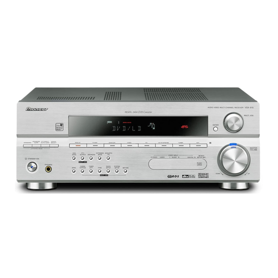
Page 80: Panel Facilities
See Display. MCACC indicator Lights when Acoustic Calibration EQ is on (Acoustic Calibration EQ is automatically set to ALL CH ADJUST after the Auto MCACC Setup or EQ Auto Setup is complete). ENTER MULTI JOG dial Use the MULTI JOG dial to select various settings and menu options. -
Page 81: Rear Panel
21 TONE reproduction of a source. Also Press this button to access the bass and treble selects the Auto Surround mode (Auto controls, which you can then adjust with the playback). MULTI JOG dial. - Page 82 16 MIDNIGHT Lights during Midnight listening. When the (STANDARD) Pro Logic II mode of the receiver is on, 2 PRO LOGIC II lights to 17 D.E. indicate Pro Logic II decoding. 2 PRO LOGIC Lights when Dialog Enhancement (DIALOG E) IIx lights to indicate Pro Logic IIx decoding (see is switched on.
-
Page 83: Remote Control
CD, DVD, etc. DISC (ENTER) can be used to enter commands for TV or DTV, and can also be used to select a disc in a multi-CD player. The following are accessed by pressing the... - Page 84 SYSTEM SETUP Component control buttons (Press RECEIVER first to access) The main buttons ( , , etc.) are used to control a component after you have selected it Use to access the System Setup menu. using the MULTI CONTROL buttons.
- Page 85 Press repeatedly to select a channel, then 15 MUTE use LEVEL +/– to adjust the level. Mutes the sound or restores the sound if it has Also adjusts the level of the been muted (adjusting the volume also Advanced Surround effects as restores the sound).
- Page 86 TV/SAT to control the receiver using the remote control if you switch the plasma AUDIO IN AUDIO IN display off AUDI O/VIDEO MULTI-CHANNEL RECEIVER he automatic volume muting feature is enabled separately...