
Related Manuals for Alfa Laval S 921


Summary of Contents for Alfa Laval S 921
- Page 1 Separator Manual High Speed Separator S 921 & S 926 Specification No. 881201-09-01 & 881201-10-01 Book No. 594863-02, rev. 3...
-
Page 2: Table Of Contents
Contents Read This First Safety Instructions Warning signs in text Environmental issues Requirements of personnel Remote start Basic Principles of Separation Introduction Separation by gravity Centrifugal separation Separating temperatures Design and function Overview The Drive Section The Process Section Sensors and indicators Separating function 4.5.1 The liquid balance in the bowl... - Page 3 Emergency stop Service, Dismantling, Assembly Periodic maintenance 6.1.1 Maintenance intervals 6.1.2 Maintenance procedure 6.1.3 Tightening of screws 6.1.4 Service kits 6.1.5 Cleaning Maintenance logs Dismantling 6.3.1 Introduction 6.3.2 Tools 6.3.3 Frame hood 6.3.4 Bowl 6.3.5 Driving device 6.3.6 Centrifugal clutch Actions before assembly 6.4.1 Cleaning...
- Page 4 Fault Finding Mechanical Functions 7.1.1 Separator vibration 7.1.2 Smell 7.1.3 Noise 7.1.4 Speed too low 7.1.5 Speed too high 7.1.6 Starting power too high 7.1.7 Starting power too low 7.1.8 Starting time too long Separating functions 7.2.1 Bowl opens accidentally during operation 7.2.2 Bowl fails to open for sludge discharge 7.2.3...
- Page 5 Storage at out of operation Before start-up...
- Page 6 Study instruction manuals and observe the warnings before installation, operation, service and maintenance. Not following the instructions can result in serious accidents. In order to make the information clear only foreseeable conditions have been considered. No warnings are given, therefore, for situations arising from the unintended usage of the machine and its tools.
-
Page 7: Read This First
Alfa Laval separator If the separator has been delivered and installed by Alfa Laval as a part of a processing system, this manual should be viewed as part of the System Documentation. Study carefully all instructions in any System Documentation. - Page 8 1 Read This First Fault Finding Refer to this chapter if the separator functions abnormally. If the separator has been installed as a part of a processing system, always refer to the trouble-tracing instructions, in the System Documentation. Technical Reference This chapter contains technical data concerning the separator and drawings.
-
Page 9: Safety Instructions
Strictly follow the instructions for installation, operation and maintenance. • Ensure that personnel are competent and have sufficient knowledge of maintenance and operation, especially concerning emergency stopping procedures. • Use only Alfa Laval genuine spare parts and the special tools supplied. - Page 10 If excessive vibration occurs, stop separator and keep bowl filled with liquid during rundown. • Use the separator only for the purpose and parameter range specified by Alfa Laval. • Check that the gear/pulley ratio is correct for power frequency used. If incorrect, subsequent overspeed may result in a serious break down.
- Page 11 2 Safety Instructions Electrical hazard • Follow local regulations for electrical installation and earthing (grounding). • To avoid accidental start, switch off and lock power supply before starting any dismantling work. Crush hazards • Use correct lifting tools and follow lifting instructions.
- Page 12 2 Safety Instructions Flying objects • Risk for accidental release of snap rings and springs when dismantling and assembly. Wear safety goggles. Health hazards • Risk for unhealthy dust when handling friction blocks/pads. Use a dust mask to make sure not to inhale any dust...
-
Page 13: Warning Signs In Text
2 Safety Instructions Warning signs in text Pay attention to the safety instructions in this manual. Below are definitions of the three grades of warning signs used in the text where there is a risk for injury to personnel. DANGER indicates an imminently hazardous situation which, if not avoided, will result in death or serious injury. -
Page 14: Environmental Issues
2 Safety Instructions Environmental issues Unpacking Packing material consists of wood, plastics, cardboard boxes and in some cases metal straps. Wood and cardboard boxes can be reused, recycled or used for energy recovery. Plastics should be recycled or burnt at a licensed waste incineration plant. -
Page 15: Requirements Of Personnel
2 Safety Instructions Requirements of personnel Only skilled or instructed persons are allowed to operate the machine, e.g. operating and maintenance staff. • Skilled person: A person with technical knowledge or sufficient experience to enable him or her to perceive risks and to avoid hazards which electricity/mechanics can create. - Page 16 2 Safety Instructions...
-
Page 17: Basic Principles Of Separation
3 Basic Principles of Separation Introduction The purpose of separation can be: • to free a liquid of solid particles, • to separate two mutually insoluble liquids with different densities while removing any solids presents at the same time, • to separate and concentrate solid particles from a liquid. -
Page 18: Centrifugal Separation
3.4 Separating temperatures 3 Basic Principles of Separation Centrifugal separation In a rapidly rotating bowl, the force of gravity is replaced by centrifugal force, which can be thousands of times greater. Separation and sedimentation is continuous and happens very quickly. The centrifugal force in the separator bowl can achieve in a few seconds what takes many hours in a tank under influence of gravity. -
Page 19: Design And Function
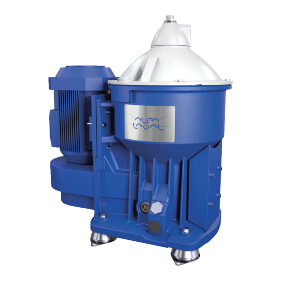
4 Design and function G08706w1 1. Process section The feed inlet and outlets are situated at the top of the separator. The liquid is cleaned in the rotating separator bowl inside the frame hood. 2. Sensors The separator is monitored by a speed sensor. An unbalance sensor and an interlocking switch are optional. -
Page 20: Overview
4.1 Overview 4 Design and function Overview The separator comprises a process section and a drive section powered by an electric motor. The separator frame comprises a lower body and a frame hood. The motor is attached to the frame. The frame feet dampen vibration. The bottom part of the separator contains a flat belt transmission, a centrifugal clutch and a vertical spindle. -
Page 21: The Drive Section
4 Design and function 4.2 The Drive Section The Drive Section The separator bowl is driven by an electric motor via a belt transmission. The belt pulley on the motor shaft includes a centrifugal clutch. The centrifugal clutch (2) with friction pads ensures a gentle start and smooth acceleration, and at the same time prevents overloading of the belt and motor. -
Page 22: The Process Section
4.3 The Process Section 4 Design and function The Process Section The separation process takes place inside the rotating separator bowl. The feed and outlet of process liquid takes place in the in and outlet unit on top of the separator frame hood. Inlet and outlet The inlet and outlet unit consists of the following parts:... - Page 23 4 Design and function 4.3 The Process Section Separator bowl The separator bowl, with its sludge discharge mechanism, is built-up as follows: The bowl body and bowl hood are held together by a lock ring (Centrilock). Inside the bowl are the distributor and the disc stack.
-
Page 24: Sensors And Indicators
4.4 Sensors and indicators 4 Design and function Sensors and indicators The separator is equipped with a speed sensor. As options, an unbalance sensor and an interlocking kit can be fitted. Speed sensor (optional) A speed sensor (3) indicates the speed of the separator. -
Page 25: Separating Function
4 Design and function 4.5 Separating function Separating function The separator separates water and solids from the uncleaned oil. Water normally leaves the separator through the water outlet. During sludge discharge, solids (sludge) and water are removed through the discharge ports. 4.5.1 The liquid balance in the bowl The liquid levels in the bowl depend on many... -
Page 26: Liquid Flow
4.5 Separating function 4 Design and function 4.5.2 Liquid flow Unseparated oil is fed into the bowl through the inlet pipe and travels via the distributor towards the periphery of the bowl. When the oil reaches slots in the distributor, it rises through the channels formed by the disc stack, where it is evenly distributed. -
Page 27: Discharge Of Sludge And Water (Alcap™ Concept)
4 Design and function 4.5 Separating function 4.5.3 Discharge of sludge and water (ALCAP™ concept) As the sludge space fills up and water enters the disc stack, traces of water will escape with the cleaned oil. The increase of water content in the cleaned oil is the sign of reduced separation efficiency. -
Page 28: Discharge Of Water Through Water Outlet
4.5 Separating function 4 Design and function 4.5.4 Discharge of water through water outlet G08862b1 Discharge of water through water outlet A. Unseparated oil B. Separated oil C. Water 1. Water paring tube 2. Water paring chamber 3. Holes in distributor 4. -
Page 29: Operating Instructions
5 Operating Instructions These operating instructions describe routine procedures to follow before and during the start, running and stopping sequences of the separator. If system documentation is available, always follow the operating instructions therein. If there is no system documentation, the instructions below are to be followed. -
Page 30: Start After Service
5.1 Before first start 5 Operating Instructions • Remove the oil pin and make sure that the oil level is above the lower end of the pin, see change on page 159. Too much or too little oil can damage the separator bearings. -
Page 31: Normal Operation
5 Operating Instructions 5.2 Normal operation Normal operation 5.2.1 Before normal start To achieve the best separation results, the bowl should be in a clean condition. Check: that all couplings and connections (1) are securely tightened to prevent leakages. Leaking hot liquid can cause burns. -
Page 32: Start
5.2 Normal operation 5 Operating Instructions 5.2.2 Start Start of separator: a. Open the water supply valve. b. Start the separator by pushing the start button at the starter unit. After every start the separator must always be run continuously for a minimum of 1 hour to ensure proper lubrication. - Page 33 5 Operating Instructions 5.2 Normal operation Ensure that the separator is at full speed. The time by full speed can be checked by studying the ammeter. Current increases during start (1). When full speed has been reached, the current decreases to a stable value (2). For normal length of the start-up period, see Technical data on page 179.
-
Page 34: Operating
5.2 Normal operation 5 Operating Instructions 5.2.3 Operating Checkpoints during operation. Burning hazard Lubricating oil and various machine surfaces can be hot and cause burns. a. Check all connections for leakage. b. Check that the feed has correct flow and temperature. - Page 35 5 Operating Instructions 5.2 Normal operation 5.2.3.1 Sludge discharge Turn off the oil feed. Perform a displacement of the oil by adding hot water (not more than bowl volume). Perform a sludge discharge. a. Add opening water until a discharge sound is heard (max.
-
Page 36: Stop
5.2 Normal operation 5 Operating Instructions 5.2.4 Stop Stopping the separator. Turn off the oil feed. Perform a displacement of the oil by adding hot water (not more than bowl volume). Perform a sludge discharge. a. Add opening water until a discharge sound is heard (max. - Page 37 G0871381 Disintegration hazard After an emergency stop, the cause of the fault must be identified. If all parts have been checked and the cause not found, contact Alfa Laval for advice before restarting the separator.
- Page 38 7 Fault Finding These fault finding instructions are for the separator only. If a fault occurs, study the System Documentation fault finding section (if applicable). Mechanical Functions 7.1.1 Separator vibration Disintegration hazards If excessive vibration occurs, stop separator and keep bowl filled with liquid during rundown.
- Page 39 7.1 Mechanical Functions 7 Fault Finding 7.1.2 Smell Cause Corrective action None. Normal occurrence during start while the friction blocks are slipping. If smell continues when separator is at full speed, stop the separator and replace friction blocks. Oil level in oil sump too low. Check oil level and add oil if necessary.
- Page 40 7 Fault Finding 7.1 Mechanical Functions 7.1.6 Starting power too high Cause Corrective action Incorrect transmission parts (60 Hz belt pulley for 50 Hz power supply). Stop and change the belt transmission to suit the power supply frequency. Wrong direction of rotation. Change electrical phase connections to the motor.
- Page 41 7.2 Separating functions 7 Fault Finding Separating functions 7.2.1 Bowl opens accidentally during operation Cause Corrective action Strainer in the operating water supply is clogged. Clean the strainer. No water in the operating water system. Check the operating water system and make sure the valve(s) are open.
- Page 42 7 Fault Finding 7.2 Separating functions 7.2.4 Bowl fails to close Cause Corrective action Nozzle in operating slide clogged. Clean nozzle. Hoses reversed. Adjust. Rectangular ring in discharge slide is defective Renew rectangular ring. Valve plugs in operating slide missing or Renew valve plugs.
- Page 43 7.2 Separating functions 7 Fault Finding...
- Page 44 8 Technical Reference Product description Alfa Laval ref. 594174 Rev. 0 Alfa Laval ref. 594175 Rev. 0 The separator is a component operating in an integrated system including a monitoring system. If the technical data in the system description does not agree with the technical data in this instruction manual, the data in the system description is the valid one.
- Page 45 8.1 Product description 8 Technical Reference 8.1.1 Directives and standards Alfa Laval ref. 591985 Rev. 3 Declaration of Incorporation of partly completed Machinery. The machinery complies with the relevant, essential health and safety requirements of the Machinery Directive 2006/42/EC To meet these requirements the following standards have been used...
- Page 46 8 Technical Reference 8.2 Technical data Technical data Alfa Laval ref. 574297 Rev. 3 Subject Value Unit General technical data: Motor power: 5,5 / 6,4 kW 50Hz/60Hz Jp reduced to motor 5,01/3,45 50Hz/60Hz Gear ratio: 50 Hz 283 / 70...
- Page 47 8.3 Connection list 8 Technical Reference Connection list Alfa Laval ref. 567321 Rev. 2 Connection Description Requirements/limits Inlet for process liquid - Max. Allowed density 8.2 Technical data on page 179. - Allowed flow Max. 4,5 m³/h - Allowed temperature Min.
- Page 48 8 Technical Reference 8.3 Connection list Connection Description Requirements/limits Motor for separator - Allowed frequency variation ± 5% (momentarily during 5 seconds) ± 10% Speed sensor for bowl spindle 8.4 Interface Description on page 182. - Type Inductive proximity switch - Supply voltage, nominal - With sensor activated (near metal) •...
- Page 49 8.4 Interface Description 8 Technical Reference Interface Description Alfa Laval ref. 564834 Rev. 3 8.4.1 Scope This document gives information, requirements, and recommendations about operational procedures and signal processing for safe and reliable operation of the separator. It is intended to be used for designing auxiliary equipment and control systems for the separator.
- Page 50 8 Technical Reference 8.4 Interface Description 8.4.4 Goal To eliminate situations that can cause harm, i.e. injury, damage to health or property and unsatisfactory process result are e.g.: Situation Effect Unbalance caused by uneven sediment Too high stress on bowl and bearing system accumulation in the bowl.
- Page 51 8.4 Interface Description 8 Technical Reference If above conditions are not fulfilled the separator will be in SERVICE mode. Stand still means: • The power to the separator motor is off • The bowl is not rotating. Starting means: • The power to the separator motor is on.
- Page 52 8 Technical Reference 8.4 Interface Description 8.4.6 Remote start This machine may be started from a remote location under the following conditions; • First start after any kind of service or manual cleaning must be supervised locally in order to ensure that no mistakes has been made during assembly.
- Page 53 8.4 Interface Description 8 Technical Reference 740 Speed sensor A proximity sensor of inductive type according to Namur standard is giving a number of pulses per revolution of the bowl (see Connection List). Signal processing in STARTING: • The separator should be stopped automatically according to NORMAL STOP procedure and an alarm should be given when the accumulated time for acceleration is longer...
- Page 54 8 Technical Reference 8.4 Interface Description Signal processing in RUNNING: • If the speed exceeds “Bowl speed, synchronous” in Technical Data with more than 5% for a period longer than 1 minute or momentarily during maximum 5 seconds more than 10% the separator shall be stopped automatically by NORMAL STOP and a high speed alarm shall be given.
- Page 55 8.4 Interface Description 8 Technical Reference The vibration monitor shall include self check function to be performed at least at initiation of STARTING. If vibrations exceed the second alarm level the separator shall be stopped the quickest way possible and it shall not been restarted until the reasons for the unbalance have been found and measures to remove them have been taken.
- Page 56 8 Technical Reference 8.4 Interface Description Signal processing in STARTING, RUNNING and CLEANING: • If the circuit is broken the separator should be stopped automatically by NORMAL STOP. This is to minimise the risk of having access to moving parts. Fluid connections Complementary information is given in the document Connection List.
- Page 57 8.4 Interface Description 8 Technical Reference 375 Inlet for discharge and make-up liquid Processing in all modes: • It is recommended to supervise the supply pressure. If pressure is too low (see Connection List), start should be interlocked and if it happens in PRODUCTION or CLEANING turn over to STAND BY should take place.
- Page 58 4. 6,5 < pH < 9 Bicarbonate content (HCO ) min. 70 mg HCO per litre, which corresponds to 3,2 °dKH. Alfa Laval accepts no liability for consequences arising from unsatisfactorily purified operating water supplied by the customer.
- Page 59 8.6 Drawings 8 Technical Reference Drawings 8.6.1 Basic size drawing Alfa Laval ref. 574283 Rev. 0 G1028611 Connection house, with connections 201, 220 and 221, turnable in 60° steps all around. All connections to be installed non-loaded and flexible. All dimensions are nominal. Reservation for individual deviations due to tolerances.
- Page 60 8 Technical Reference 8.6 Drawings 8.6.2 Foundation drawing Alfa Laval ref. 574284 Rev. 1 G1028711 A. Centre of separator bowl. B. Holes for foundation bolts (8x). C. Centre of motor. D. Min. lifting capacity required during service: 300 E. Max. height of largest component incl. lifting tool.
- Page 61 8.6 Drawings 8 Technical Reference 8.6.3 Interconnection diagram Alfa Laval ref. 561786 Rev. 5 G1019311 Wiring without junction box Wiring of connector “X”: Wire colour codes: Junction box RD=A BK=Black BU=B BN=Brown 740: Speed sensor, (bowl speed) GN=C BU=Blue 752:...
- Page 62 8 Technical Reference 8.6 Drawings 8.6.4 Electric motor Alfa Laval ref. 565595 Rev. 11 G1028881 Manufacturer: ABB Motors Type of mounting Degree of protection Type: M3AA 112 MB2 IEC 34-7 IEC 34-5 Poles: IM 2111 IP 55 G0541421 Bearings: D-end 6306-2Z/C3...
Need help?
Do you have a question about the S 921 and is the answer not in the manual?
Questions and answers