Table of Contents
Advertisement
Quick Links
Advertisement
Table of Contents

Related Manuals for Robe iBOLT


Summary of Contents for Robe iBOLT
- Page 1 QR code for user manual Version 2.1...
-
Page 2: Table Of Contents
16.2 Torques of Pan/Tilt motors screws ................. 60 16.3 Checking and replacing the silica gel desiccants ..........61 16.4 Disposing of the product ..................63 17. Robe Ethernet Access Portal (REAP) ............... 64 18. Technical Specifications .................... 72 19. ChangeLog ......................... 76... -
Page 3: Safety Instructions And Operating Determinations
The manufacturer will not accept liability for any resulting damages caused by the non-observance of this manual or any unauthorized modification to the device. The Robin iBOLT was designed for outdoor use and it is intended for professional application only. It is not for household use. - Page 4 The user or service worker must not remove covers of the laser source! The user or service worker must not do any servis works on the laser source! Operators shall control access to the beam within the hazard distance or install the devicet at the height that will prevent spectators’...
- Page 5 Always keep transparent covers of LIDAR sensors on the device head clean and do not block them with any objects. Warning! If some obstacle (person, object) appears in the light beam in distance to 5 metres from the device, its light output is automatically closed. It is a default setting of the device. Change of the safety function can be done by means of DMX channel 8 (Safety control, Lidar distance setting).
- Page 6 Please use only an original ROBE packaging (paper box, loader case or foam shell) for transporting the device, otherwise potential damage of the device during its transport...
- Page 7 When the new device (device directly from the manufacturer) is switched on for the first time, the light output from the device is disabled (dimmer is closed). Enabling light output from the device can be done only in two ways: 1.
-
Page 8: Loader Case Manipulation
The iBolt can be placed in the loader case in two ways. Fixture base down Place the iBolt on the bottom part (3) of the loader case and slide the middle part (2) with the top part (1) on the iBolt. - Page 9 Fixture base up Remove the top part (1) of the loader case and insert the iBolt into the middle part (2) of the loader case and close the case by the top part (1). The iBOLT is heavy, two persons should manipulate with it. During manipulation, the...
-
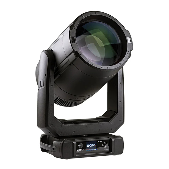
Page 10: Fixture Exterior View
3. Fixture exterior view 1 - Transparent covers of LIDARS 2 - Head 3 - Tilt lock 4 - Arm 5 - Handle 6 - Pan lock 7 - Base 8 - Front lens The head has to be locked for transportation - the tilt lock latch (3) and the pan lock latch (6) have to be in the locked positions. -
Page 11: Installation
Fixtures must be installed by a qualified electrician in accordance with all national and local electrical and construction codes and regulations. The Robin iBOLT´s panel connectors are dust and water protected according to IP 65 by mating with related cable connectors. They cannot stay disconnected outdoor. -
Page 12: Connection To The Mains
(residual-current circuit breaker)! Wiring and connection work must be carried out by a qualified electrician. The Robin iBOLT is equipped with auto-switching power supply that automatically adjusts to any 50-60Hz AC power source from 100-240 Volts. Mains cable powerCON TRUE1 In/open ended is enclosed to the fixture. -
Page 13: Replacing Rotating Gobos
4.2 Replacing rotating gobos Unplug the fixture from mains before replacing the gobos! Do not replace gobos in a damp environment (e.g. rain, snowfall)! Do not remove fixture covers in smoky or particularly dirty environment (e.g. with fog machines). 1. Close a light output of the fixture and allow the fixture to cool about 40 minutes. 2. - Page 14 the accessible position for its changing. Note: "G1-Mg" means the gobo holder with a magnet. 6. Check that the position point (7) on the gobo holder aims exactly to the toothlike projection (8) on the edge of the rotating gobo wheel. If not, go to the option "Gobo Offset" and adjust the position point (7) exactly opposite of the toothlike projection (8).
- Page 15 Warning! Use only gobos intended for the Robin iBOLT. Do not try to use gobos from the Robin Pointe. Orientation of gobos in the gobo holders: 11. Insert the gobo holder (4) back into rotating gobo wheel (3) in this way, that its position point (7) has to aimed at a small toothlike projection (8) on the edge of the rotating gobo wheel.
- Page 16 13. Switch the fixture off, place the head cover back on the fixture and screw it by means of the six hex socket head screws M5x16. Keep required tightening torque as stated in the chapter Maintenance. Do not forget to connect grounding wire between chassis and head cover. 14.
-
Page 17: Rigging The Fixture
4.3 Rigging the fixture A structure intended for installation of the fixture(s) must safely hold weight of the fixture(s) placed on it. The structure has to be certificated to the purpose. The fixture (fixtures) must be installed in accordance with national and local electrical and construction codes and regulations. - Page 18 Omega holders points Truss installation 1. Bolt each clamp (1) to the omega holder (2) with M12 bolt and lock nut through the hole in the holder. 2. Fasten the omega holders to the bottom of the base by inserting both quick-lock fasteners (3) into the holes of the base and tighten fully clockwise.
- Page 19 Allowed installation positions of the iBOLT: Note for open-air installation: if the fixture has to stand on the ground, min. distance of 4" (10cm) between the fixture base and the ground has to be kept.
-
Page 20: Dmx-512 Connection
4.4 DMX-512 connection The fixture is equipped with 5-pin XLR sockets for DMX input and output. Use a shielded twisted-pair cable designed for RS-485 and 5-pin XLR-plugs and connectors in order to connect the controller with the fixture or one fixture with another. DMX output DMX input XLR mounting sockets (rear view):... -
Page 21: Ethernet Connection
The Universe is a single DMX 512 frame of 512 channels. The Robin iBOLT is equipped with 8-pin RJ- 45 sockets for Ethernet connection. Use a network cable category 5 (with four “twisted” wire pairs) and standard RJ-45 plugs in order to connect the fixture to the network. - Page 22 The fixture is equipped with Ethernet Pass through switch which sustains Ethernet integrity, when the fixture has no power, it automatically maintains network connectivity. If you use the Ethernet IN-OUT way for the Ethernet connection, max. 8 fixtures can be connected in the IN-OUT line.
-
Page 23: Wireless Dmx Operation
4.6 Wireless DMX operation The ROBE wireless DMX/RDM module has full support for wireless communication protocols at entertainment market. Module is based on well known LumenRadio RF technology, with implemented wire interface for con- nection with Robe products. RF output for MCX interface antenna as standard output. -
Page 24: Stage Mode And Sky Mode
Switching between the Stage mode and the Sky mode during programming is possible, but safety requirements for Sky mode must be observed. Stage mode - the mode is set as DEFAULT mode in the new iBolt from the factory and is also activated after using the function Default Settings (tab "Personality", option "Default Settings"). - Page 25 Sky mode - the fixture utilize all power of the light source during all procedures of its operation. The device operated in the SKY MODE must not be pointed at any time and any circumstances to the spectators or to the spaces where people can appear. The light output from the device in the SKY MODE must not aim - to the area where people or animals can occur - to the populated area...
-
Page 26: Fixture Operation With Lidar
4.8 Fixture operation with LIDAR The fixture is equipped with two LIDAR sensors placed on the front of the head (under glass covers). Behaviour of the LIDAR sensors can be set by means of the channel 8 (Safety control). The channel allows you to set a distance to which the light output from the fixture will be automatically closed if some obstacle (person, object) will appear in the light beam. -
Page 27: Checking The Ip65 Integrity Of The Fixture
5. Checking the IP65 integrity of the fixture. The Robin iBOLT is IP65 rated lighting fixture which has been designed to be protected against the ingress of dust and pressure water jets from any direction. 1. Smart pressure test - for this test serves the function "Pressure Test" in the tab Service. Unique testing procedure allows you easy testing of the IP65 integrity of the fixture. - Page 28 "Enhanced pressure test". For this type of pressure test is needed the Pressure IP Testing Set ROBE (P/N 10980659). Please ask your ROBE distributor for help. The message "Valve Seal Error" means that valve or coil in the valve is defective or there is a connection problem.
-
Page 29: Operating The Fixture At Ambient Temperatures Below 0°C
150 mbar maximally! 6. Operating the fixture at ambient temperatures below 0°C Design of the iBOLT allows its operation at ambient temperature up to -30°C, but you have to take some specific into account before operating the fixture. 1.Fixture is not in Standby mode. -
Page 30: Standby Mode
7. Standby mode The fixture can be switched to Standby mode by means of web interface REAP or DMX command (channel Power/Special functions, DMX values 22-23). Standby mode can be cancelled by means of web interface REAP, DMX command (channel Power/Special functions, DMX values 24-25) or by switching the fixture off and on. -
Page 31: Remotely Controllable Functions
8. Remotely controllable functions Colour wheel This wheel contains 13 dichroic filters + open.The colour wheel can be positioned between two adjacent col- ours in any position. It is also possible to rotate the colour wheel continuously at different speeds ("Rainbow effect“... - Page 32 Pan/Tilt Fast pan/tilt movement due to built-in electronic motion stabilizer (EMS). The electronic motion stabilizer ensures precise position of the fixture´s head during its movement and reduces its swinging when the truss shakes. Motionless absolute positioning system for Pan and Tilt (MAPS) Pan /Tilt movement range: 0-540°/0-265°.
- Page 33 Pan control channel - shortcut on/off Pan control channel = 0 DMX (default value). Pan range = 540°, shortcut Off If the pan receives a value 255 DMX from a DMX controller and next received DMX value for the pan will be 0 DMX, the pan will move to the point 0 DMX around entire track 255-0 DMX.
-
Page 34: Control Menu Map
9. Control menu map Default settings=Bold print Level 1 Level 2 Level 3 Level 4 Level 5 Level 6 Addressing DMX Address 001-512 DMX Preset Channels Dimmer F. Ethernet Settings Ethernet Mode Disable ArtNet gMAI gMA2 sACN Ethernet To DMX Off, On IP Address/Net Mask Default IP Address... - Page 35 Level 1 Level 2 Level 3 Level 4 Level 5 Level 6 SW HW Versions M Product IDs Mac Address RDM UID RDM Label View Logs Fixture Errors Fixture States Power On Power Off Fixture Position Fixture Temperatures LEDs B.1 Temperature LEDs B.2 Temperature Base Temperature Sensors Logs...
- Page 36 Level 1 Level 2 Level 3 Level 4 Level 5 Level 6 1200Hz 2400Hz Frequency Adjust Init Effect Positions 0-255 Dimmer Fine 0-255 Reset Init Effect Pos. Screen Settings Display Intensity 1-10 Off-10min. Screen Saver Delay Touchscreen Lock Off-10min. Recalibrate Touchscreen Display Orientation Normal Inverted...
- Page 37 Level 1 Level 2 Level 3 Level 4 Level 5 Level 6 Static Gobo Rot. Gobo Wheel 1 0-255 R. Gobo Index 1/1 0-255 R. Gobo Index 1/9 0-255 Prism 1 0-255 Prism 1 Rot.1 0-255 Prism 1 Rot.2 0-255 Prism 1 Rot.3 0-255 Prism 2...
-
Page 38: Control Menu
- [slider control] used to recall slider system for setting desired value. - [keyboard control] used to recall keyboard system for setting desired value. After switching the fixture on, the screen shows the screen with the ROBE logo. Battery indication... - Page 39 The green icon at the top right corner of the screen indicates the level of the display battery charging. If the whole icon is green, the battery is fully charged while the red icon indicates exhausted battery. The battery charges during fixture operation, its charging lasts cca 6 hours. We recommend that the fixture should be in operation at least 7 hours per week to keep the battery fully charged.
- Page 40 REAP. Locking/unlocking the screen. To lock the screen, display the screen with ROBE logo, touch the [ESCAPE] button and slide your finger clockwise in a circular track of 360° across buttons [ESCAPE] --> [NEXT] --> [ENTER/Display On] -->[PREV]--> [ESCAPE].
-
Page 41: Tab " Address
Resettable Hours - The item shows the number of the operation hours that the Robin iBOLT has been powered on since the counter was last reset. In order to reset this counter to 0, touch the text box next to the item "Resettable Hours:"... - Page 42 RAINS Status - The menu item gives you information about environment in the fixture. RAINS (Robe Automatic Ingress Neutralization System) manages humidity, temperature and pressure control using an active monitoring system to automatically remove any moisture detected within the fixture and provides permanent monitoring to ensure peak performance of the fixture.
- Page 43 The bar chart MAX WET informs you about maximum humidity achieved in the fixture since the chart was last reset. The bar chart also informs you about saturation of silica gel desiccants in the fixture arm with water and is deciding indicator for their checking and replacement. The option MAX WET reset resets the bar chart MAX WET.
- Page 44 Module H - a Laser control processor (backup) Module O - a Focus/Zoom control processor Module P - a Prisms/frost control processor Module DL- a Data Logger control module Module GR- a Gyroscope control module Module FAN- a Fans control module Module T - a Focus/Zoom control processor (backup) Product IDs - The menu is used to read the MAC Address, RDM UID and RDM Label.
-
Page 45: Tab "Personality
10.3 Tab "Personality" DMX Preset Channels - The menu item offers you overview of DMX channels used in the fixture. DMX Input- Use the menu to select mode of DMX signal receiving. Wired - DMX signal is received by means of the standard DMX cable. Wireless - DMX signal is received by means of the inbuilt wireless module. - Page 46 Password Protection - allows to enter password in order to prevent unauthorized person from changing setting of the fixture. Password is set to 7623 and cannot be changed. Reset Web Password - The menu item allows you to reset a password for access to the REAP (default pass- word: 2479, user: robe).
-
Page 47: Tab "Manual Control
10.4 Tab "Manual Control" Reset Functions - The menu allows to reset the fixture either per function modules or all modules together. Total System Reset - The item resets all function modules. Pan/Tilt Reset - The item resets pan and tilt. Colour Reset - The item resets colour wheel and CMY system. - Page 48 Calibration of the effects via the control board 1. Disconnect DMX controller from the fixture and enter the "Calibrate Effects" menu. 2. Use the [up arrow] and [down arrow] to find "Pan" and press [Enter] to enter the fine effect adjustment screen. 3.
-
Page 49: Software Update
11. Software update For software update of the fixture serves Robe Toolkit. The Robe Toolkit is a universal tool for Robe fixtures which includes Device Updater, Library Manager, Device Manager and simple DMX controller. Please see the Toolkit user manual for more details about fixture update. -
Page 50: Rdm
DMX512, the RDM protocol allows a console or dedicated RDM controller to send commands to and receive messages from specific moving lights. RDM allows explicit commands to be sent to a device and responses to be received from it. The list of commands for Robin iBOLT is the following: Parameter ID Discovery command SET command... -
Page 51: Error And Information Messages
13. Error and information messages Error in the fixture is signalled by the yellow warning icon at the bottom line of the screen: Touch the warning icon or press the [ESCAPE] button to display error messages. List of error and information messages: Pan Error 1 Mechanical end of the pan track was not detected. - Page 52 Focus 1 Error 1 Impact to the mechanical end of the focus module track was not detected. Focus Error 4 Incorrect detection of a focus track. Impact to a mechanical obstruction was detected within running of the focus module. Gobo Carousel Error 1 Magnetic/optic sensor was not detected.
-
Page 53: Nfc
The NFC point is situated on the front panel of fixture´s base. Download and install the ROBE COM from Google Play (for Android 5.0 and higher) or App Store (for iOS 12.0 and higher) to your mobile phone. Your mobile phone has to support NFC. -
Page 54: Maintenance
Another maintenance and service operations should be carried out by trained technician only. If you need any spare parts, please order genuine parts from your local Robe distributor. In case of problem with smooth running of CMY colour mixing system, lubricate sliding bars of CMY flags. As lubricant we recommend ÄRONIX silicone oil 500 cSt - it is a medium viscosity lubricant, release agent, high... - Page 55 Replacing the battery. Before replacing the battery, disconnect the fixture from mains. 1. Using a flat-blade screwdriver, unscrew (anti-clockwise) the metal cover of battery compartment from rear panel of the base. 2. Loosen (anti-clockwise) the battery holder cap. 3. Remove the exhausted battery from the battery holder. 4.
-
Page 56: Fixture Watertight Covers And Torques Of Covers Screws
16.1 Fixture watertight covers and torques of covers screws Keep values of torques as stated on pictures below otherwise leakage issues can occur! Run the procedure Pressure Test (Service Pressure Test) after replacing --> any watertight cover! Bottom base cover 16 x hex socket head screw M4x14 Screws must be tightened Tightening torque*: 2.5 Nm... - Page 57 Head covers (on both sides of the head) Screws must be tightened 6 x hex socket head screw M5x16 in the order 1-->6 Tightening torque*: 2.5 Nm * Tighten all screws in two steps: Step 1 - use tightening torque 0.5Nm (pre-tightening) Step 2- use tightening torque 2.5Nm (final tightening) Carefully check the gasket for signs of deformities or damages and if it is correctly placed before screwing head covers back.
- Page 58 Yoke cover Screws must be tightened 8 x hex socket head screw M4x8 in the order 1-->8, Tightening torque*: 2.5 Nm * Tighten all screws in two steps: Step 1 - use tightening torque 0.5Nm (pre-tightening) Step 2- use tightening torque 2.5Nm (final tightening) Carefully check the gasket for signs of deformities or damages and if it is correctly placed before screwing the yoke cover back.
- Page 59 Cover of laser section Screws must be tightened 4 x hex socket head screw M5x12 in the order 1-->4, Tightening torque*: 2.5 Nm * Tighten all screws in two steps: Step 1 - use tightening torque 0.5Nm (pre-tightening) Step 2- use tightening torque 2.5Nm (final tightening) Carefully check the gasket for signs of deformities or damages and if it is correctly placed before screwing the cover of laser source back.
-
Page 60: Torques Of Pan/Tilt Motors Screws
16.2 Torques of Pan/Tilt motors screws In case of change of pan motor or tilt motor or pan/tilt control PCB (RB 3138 in the fixture yoke), you have to run the procedure Calibrate Pan/Tilt Reset in the tab "Service" (tab Service--> Calibrations --> Calibrate Pan/ Tilt Reset). -
Page 61: Checking And Replacing The Silica Gel Desiccants
16.3 Checking and replacing the silica gel desiccants The silica gel desiccants are used for humidity indication in the fixture. Dry silica gel has an orange colour, if it is saturated with water, its colour changes to dark grey. If most of silica gel changed colour to dark grey, it has to be replaced. - Page 62 Each silica gel box is fastened in the fixture by means of two screws. Example: Dry silica gel Silica gel saturated with water The silica gel desiccants in the fixture head should be checked (and alternatively replaced) at removing head covers, e.g.
-
Page 63: Disposing Of The Product
In case that silica gel in the fixture arm is fully saturated with water, the warning message " Too Much Humidity in Device" will appear on the fixture display (yellow warning icon) and also in the Robe Ethernet Access Portal (Logs screen). -
Page 64: Robe Ethernet Access Portal (Reap)
You do not need change any IP settings on the fixture, there is no need to set the fixture into Art-Net mode. Type the IP address of the iBOLT to your web browser, e.g. http://2.248.16.0, enter the user name: robe and the password: 2479, the Status screen of the iBOLT will appear. - Page 65 10 minutes of its operating, after closing fixture dimmer etc. RAINS (Robe Automatic Ingress Neutralization System) manages humidity, temperature and pressure control using an active monitoring system to automatically remove any moisture detected within the fixture and provides permanent monitoring to ensure peak performance of the fixture.
- Page 66 Desiccants saturated with water Device status ready means, that all fixture resets are OK and the fixture is ready for operation. It does not assess state of desiccants or result of pressure test! Desiccants fully saturated with water Silica gel desiccants in the fixture arm should be replaced. After replacing them, reset MAX WET resettable bar chart.
- Page 67 The Personality screen allows you to set fixture behaviour and run a pressure test. The icon allows you to change values in a corresponding table. Example for Pan/Tilt settings: The table "Pressure test " with green button Start test allows you to run a procedure which checks IP65 in- tegrity of the fixture.
- Page 68 Examples of pressure test messages: Pressure test is 10 minutes delayed due to fixture cooling Pressure test is running Pressure test passed Pressure test failed The screen Logs displays operating information of the fixture which have been saved. The icon offers you two options: "Download log file"...
- Page 69 The option Logs filter allows you to select desired group of recorded errors and recorded operating values. Expanded menu Logs filter If the option "all must pass" is checked, only logs which contain all selected errors will be displayed. Menu "Sorting filter pass" --> option "single groups" means that logs which contain at least one selected error will be displayed.
- Page 70 You can select range of temperature, humidity and pressure in desired time interval. Tab Pressure measurements shows history of pressure tests. If you have two and more iBOLTs, the Discovery screen allows you to show all connected iBOLTs in network. Click on the blue button Discover and fixtures connected in the network will be displayed.
- Page 71 Example: Fixture which do not communicate with computer are indicated by yellow background. If the option Move devices with warning to top is checked, fixtures with some error will be displayed on the top of fixture list. The option Columns selection allows you to check desired items which will be displayed in columns. Max. 6 items can be selected.
-
Page 72: Technical Specifications
18. Technical Specifications Electrical Power supply: electronic auto-ranging Input voltage range: 100-240V, 50-60Hz Fuse: T 10A/250V ~ Max. power consumption: 700 W (power factor 0.97) Optic Light source type: LSW-5™ 500W White Laser Source Zoom optical system: 21:1 Zoom range: 0.4° - 8.5° Output lens diameter: 300 mm Illuminance: 120 000 lx @ 100 m Colour wheel... - Page 73 Gobos order: Prism wheel 1 1- Rotating 6-facet linear prism with continuous rotation in both directions 2- Rotating 6-facet linear multicoloured prism with continuous rotation in both directions 3- Rotating 8-facet 12° circular prism with continuous rotation in both directions Prism wheel 2 1- Rotating 6-facet linear prism with continuous rotation in both directions 2- Rotating 32-facet circular prism with continuous rotation in both directions...
- Page 74 2 user editable programs, each up to 80 steps Supported protocols: USITT DMX 512, RDM, ArtNet, MA Net, MA Net2, sACN 1 DMX mode (37 control channels) REAP™ - Robe Ethernet Access Portal Wireless DMX/RDM module type RW 001 Supported protocols: full RDM support, CRMX , W-DMX...
- Page 75 Thermal hazard distances Sky mode Min. distance from flammable surface: 0.5 m Min. distance to illuminated surface: 45 m Stage mode Min. distance from flammable surface: 0.5 m Min. zoom Min. distance to illuminated surface: 30 m (SINGLE BEAM) Min. distance to illuminated surface: 20 m (MULTIPLE BEAM output with one inserted prism) Min.
-
Page 76: Changelog
22/05/2024 Sky a Stage mode behaviour changed May 22, 2024 Copyright © 2023-2024 Robe Lighting - All rights reserved All Specifications subject to change without notice Made in CZECH REPUBLIC by ROBE LIGHTING s.r.o. Palackeho 416/20 CZ 75701 Valasske Mezirici... - Page 77 DMX protocol Robin iBOLT - DMX protocol The iBolt cannot be programmed in the Stage mode and then used in the Sky mode and vice versa. Version: 2.2 Mode 1-Standard 16-bit Mode/ Total channels Type of Function 1/37 DMX Value...
- Page 78 DMX protocol Mode/ Total channels Type of Function 1/37 DMX Value control 54-121 Reserved Dimmer curve: Linear 122-123 step 124-125 Dimmer curve: Square law step 126-127 Parking position: On step 128-129 Parking position: Off step To activate following functions (130-255 DMX), stop in DMX value for at least 3 seconds.
- Page 79 DMX protocol Mode/ Total channels Type of Function 1/37 DMX Value control 29-30 Lidar is active to 65 m step 31-32 Lidar is active to 70 m step 33-34 Lidar is active to 75 m step 35-36 Lidar is active to 80 m step 37-38 Dimmer deactivation...
- Page 80 DMX protocol Mode/ Total channels Type of Function 1/37 DMX Value control 244-249 Reserved 250-255 Auto random colour selection from fast to slow proportional Colour wheel - fine positioning 0 - 255 Fine positioning (0=default) proportional Cyan 0 - 255 Cyan from min.
- Page 81 DMX protocol Mode/ Total channels Type of Function 1/37 DMX Value control 71-72 Filter 147 (Apricot) step 73-74 Filter 148 (Bright Rose) step 75-76 Filter 152 (Pale Gold) step Filter 154 (Pale Rose) 77-78 step Filter 157 (Pink) 79-80 step 81-82 Filter 158 (Deep Orange) step...
- Page 82 DMX protocol Mode/ Total channels Type of Function 1/37 DMX Value control 40-45 Gobo 7 step 46-51 Gobo 8 step 52-57 Gobo 9 step 58-63 Gobo 10 step 64-69 Beam reducer 1 step 70-75 Beam reducer 2 step 76-81 Beam reducer 3 step 82-87 Beam reducer 4...
- Page 83 DMX protocol Mode/ Total channels Type of Function 1/37 DMX Value control 47-49 Gobo 6 step 50-52 Gobo 7 step 53-55 Gobo 8 step 56-59 Gobo 9 step Continual positioning Index - set indexing on channel 20 Open/hole proportional Gobo 1 proportional Gobo 2 proportional...
- Page 84 DMX protocol Mode/ Total channels Type of Function 1/37 DMX Value control 0 - 3 Open position/hole (0=default) step Index - set indexing on channel 23 Prism 1 - 6-facet linear step 8-11 Prism 2 - 6-facet linear multicoloured step 12-15 Prism 3 - 8-facet 12°...
- Page 85 DMX protocol Mode/ Total channels Type of Function 1/37 DMX Value control 18-19 Pattern 8 step 20-21 Pattern 9 step 22-23 Pattern 10 step 24-25 Pattern 11 step 26-27 Pattern 12 step Rotation - set rotation on channel 27 28-29 Pattern 1 step 30-31...
- Page 86 DMX protocol Mode/ Total channels Type of Function 1/37 DMX Value control 12-13 Effect 5 step 14-15 Effect 6 step 16-17 Effect 7 step 18-19 Effect 8 step 20-21 Effect 9 step 22-23 Effect 10 step 24-25 Effect 11 step 26-27 Effect 12 step...
- Page 87 0 - 255 Dimmer intensity from 0% to 100% (0=default) proportional Dimmer intensity - fine 0 - 255 Fine dimming (0=default) proportional Copyright © 2023 -2024 Robe Lighting s.r.o. - All rights reserved All Specifications subject to change without notice Page 11...
Need help?
Do you have a question about the iBOLT and is the answer not in the manual?
Questions and answers