
Related Manuals for DAHAO 41 Series


Summary of Contents for DAHAO 41 Series
- Page 1 操作手册 OWNER’S MANUAL 触摸屏 HA Touch Panel HA 花样机 Pattern Sewing Machine V 2022-02 Copyright © 2021 DAHAO Technology 版权所有,严禁擅自转载。 大豪公众号 大豪服务云...
- Page 2 前 言 欢迎您使用本公司的特种缝纫机控制系统。 请您仔细阅读本操作手册,以确保正确的操作、使用特种缝纫机,请按照本手册内注明的方式进行操 作,否则,如违规操作所造成损失本公司不承担责任。此外,请将本用户手册妥善保存在安全地点,以便 随时查阅。若发生故障须由本公司指定的技术人员或专业人员进行维修。...
- Page 4 Forewords Thank you for using our Computerized Control System for Special Sewing Machine. It is appreciated that you do read this manual carefully in order to operate the machine correctly and effectively. If the user operates the machine contrary to regulations herein, we will not take responsibility for any loss caused thereby to the user or any third party.
- Page 6 安全注意事项 1、 安全操作的标志及含义 本使用说明书及产品所使用的安全标志是为了让您正确安全的使用产品,防止您及其他人受到伤害。标志 的图案和含义如下: 如果忽视此标记而进行错误的操作,会导致人员的重伤或死亡。 如果忽视此标记而进行错误的操作,会导致人员的受伤和设备的损坏。 该符号表示“应注意事项”。三角中的图案表示必须要注意的内容。(例如左边的图案表示: “当心受伤”) 该符号表示“禁止” 该符号表示“必须”。圆圈中的图案表示必须要做的内容。(例如左边的图案表示“必须接 地”) 2、 安全注意事项 打开控制箱时,先关闭电源开关并将电源插头从插座上拔下后,等待至少 5 分钟后,再打开 控制箱盖。触摸带有高电压的区域会造成人员受伤。 使用环境 应避免在强电气干扰源(如高频焊机)的附近使用本缝纫机。 强电气干扰源可能会影响缝纫机的正常操作。 电源电压的波动应该在额定电压的±10%以内的环境下使用。 电压大幅度的波动会影响缝纫机的正常操作,需配备稳压器。 环境温度应在 0℃~45℃的范围内使用。 低温或高温会影响缝纫机的正常操作。 相对湿度应在 35%~85%的范围内,并且设备内不会形成结露的环境下使用。干燥、潮湿或结 露的环境会影响缝纫机的正确操作。 压缩空气的供气量应大于缝纫机所要求的总耗气量。压缩空气的供气量不足会导致缝纫机的 动作不正常。 万一发生雷电暴风雨时,关闭电源开关,并将电源插头从插座上拔下。雷电可能会影响缝纫 机的正确操作。 安装 请让受过培训的技术人员来安装缝纫机。 安装完成前,请不要连接电源。 如果误按启动开关,缝纫机动作会导致受伤。...
- Page 7 缝纫机头倒下或竖起时,请用双手操作。不要用力压缝纫机。 如缝纫机失去平衡,缝纫机滑落到地上会造成受伤或机器损坏。 必须接地。 接驳地线不牢固,是造成触电或误动作的原因。 所有电缆应固定在离活动部件至少 25mm 以外处。另外,不要过度弯曲或用卡钉固定得过紧。 会引起火灾或触电的危险。 请在机头上安装安全罩壳。 缝纫 本缝纫机仅限于接受过安全操作培训的人员使用。 本缝纫机不能用于除缝纫外的任何用途。 使用缝纫机时必须戴上保护眼镜。 如果不戴保护眼镜,断针时机针折断部分可能会弹入眼睛造成伤害。 发生下列情况时,请立即切断电源。否则误按下启动开关时,会导致受伤。 1.机针穿线时 2.更换机针时 3.缝纫机不使用或人离开缝纫机时 缝纫过程中,不要触摸任何运动部件或将物件靠在运动部件上,因为这会导致人员受伤或缝 纫机损坏。 如果缝纫机操作中发生误动作,或听到异常的噪声或闻到异常的气味,应立即切断电源。然 后请与购买商店或受过培训的技术人员联系。 如果缝纫机出现故障,请与购买商店或受过培训的技术人员联系。 维护和检查 只有经过训练的技术人员才能进行缝纫机的维修、保养和检查。 与电气有关的维修、保养和检查请及时与电控厂家的专业人员进行联系。 发生下列情况时,请关闭电源并拔下电源插头。否则误按启动开关时,会导致受伤。 1.检查、调整和维修 2.更换弯针、切刀等易损零部件 在检查、调整和修理任何使用气动设备之前,请先断开气源,并等压力表指针下降到“0”为 止。 在必须接上电源开关和气源开关进行调整时,务必十分小心遵守所有的安全注意事项。 未经授权而对缝纫机进行改装而引起的缝纫机损坏不在保修范围内。...
- Page 8 Safety Matters for Attention Signs & Definitions of Safety Marks 1、 This User’s Manual and the Safety Marks printed on the products are for you to use this product correctly so as to be away from personal injury. The signs and definitions of Marks are as follows: The incorrect operation due to negligence of this Mark will cause the serious personal injury or even death.
- Page 9 mechanical damage. Grounding is a must. If the grounding cable is not fixed, it may cause the electric-shock and mis-operation of the machine. All the cables shall be fixed at least 25mm away from the moving components. By the way, don’t excessively bend or over-tightly fix the cable with nails or clamps, or it may cause the fire or electric shock.
-
Page 10: Table Of Contents
目录 Forewords..................................1 Safety Matters for Attention............................I 目录....................................I 1 概要说明..................................1 1.1 概述.................................1 1.2 功能和参数..............................2 1.3 安全使用注意事项............................3 1.4 使用上的预防措施............................5 1.5 标准化................................6 1.6 操作方式................................ 6 2 操作说明..................................8 2.1 基本操作................................ 8 2.2 界面显示状态说明............................10 2.2.1 实例画面 1............................10 2.2.2 实例画面 2............................10 2.2.3 实例画面... - Page 11 2.9.5 输出信号检测............................ 65 2.9.6 连续运转............................67 2.9.7 XY 马达原点检测..........................67 2.9.8 主轴马达安装角度设置........................68 2.9.9 中压脚检测............................68 2.10 功能设定说明............................69 2.10.1 软件版本查询模式.......................... 71 2.10.2 循环程序............................71 2.10.3 面板设定............................74 2.10.4 功能快捷键............................75 2.10.5 图形管理............................76 2.10.5.1 数据传输模式........................77 2.10.5.2 格式化模式........................79 2.10.5.3 花样格式批量转换......................
- Page 12 2.2.3 Interface 3 (Catalogue Mode in Main Interface P1)................. 131 2.3 Instructions on Main Interface P1........................ 132 2.3.1 Pattern Stitch Number Display......................134 2.3.2 Speed Adjustment..........................135 2.3.3 Operation of Pattern Number Hot key....................136 2.3.4 Pattern Display...........................137 2.3.5 Sewing Fabric Thickness Setting...................... 138 2.3.6 Add counter setup..........................139 2.4 Main Interface P2............................
- Page 13 2.10.8 Encrypt.............................211 2.10.9 Password Mode..........................212 2.10.10 Date and Time Setting........................217 2.10.11 Alarm Record Mode........................219 2.10.11.1 Error Note........................... 219 2.10.11.2 Run Note..........................220 2.10.12 Update Mode..........................221 2.10.13 System Para........................... 222 2.11 Letter Sewing Edition..........................223 2.11.1 Parameters of Letter Sewing......................224 2.11.2 Adjustment of Letter Sewing Pattern....................
-
Page 14: 概要说明
1 概要说明 1.1 概述 兄弟系列工业缝纫机电脑控制系统,主轴电机采用具有世界先进水平的交流伺服控制技术驱动,具有 力矩大、效率高、车速稳定和噪音低等特点。操作面板设计多样化可满足不同客户的配套要求;系统采用 德国式结构设计,安装和维修方便快捷。... -
Page 15: 功能和参数
1.2 功能和参数 序号 控制器型号 电子花样机 X(左右)方向 Y(前后方向) 缝制范围 600(mm) 400(mm) 3000rpm(针距 3mm 以下时) 最高缝纫速度 0.1~12.7mm(最小分辨率 0.10mm) 缝迹长度 压脚送布 间断送布(脉冲马达双轴驱动方式) 41.2mm 针杆行程 DP×5、DP×17 使用机针 标准 18mm 最大 22mm(气动式最大 25mm) 外压脚上升量 中压脚 步进驱动(可调范围:0~8mm) 20mm 中压脚上升量 花样数据存储 内存/U 盘 暂停功能 在缝制途中可以让缝纫机停止 可以选择缝迹缝制花样时,可以独立地放大缩小 X、Y 轴。 放大、缩小功能... -
Page 16: 安全使用注意事项
1.3 安全使用注意事项 安装 控制箱 请遵照说明正确装好 附件 如要安装其它附件时,请先关掉电源并拔掉电源插头。 电源线 请不要用重力去压住电源线或过度的扭曲电源线。 请不要将电源线靠近转动的部位,最少要离开 25mm 以上。 控制箱要接入电源前, 请必再查看要接入的电源电压是否与控制箱上标示的电压相同及 确定位置后,才可供应电源。如有接用电源变压装置的话,同样的要检查一下后才可供 应电源。这时缝纫机上的按钮式电源开关一定要放在 [OFF]。 接地 为防止噪声干扰及漏电而发生电击事件,电源线上的接地线定要确实做好接地。 附属装置 如要接用电气方面的附属装置的话,请遵照指示的位置接好。 拆卸 要卸下控制箱时,必须要先关掉电源并拔掉电源插头。 在拔离电源插头时不可只拉电源线,必须用手拿住电源插头拔出。 ... - Page 17 错误的行动可能会发生重伤或死 错误的行为可能会发生伤害或房 亡 屋或财产的损害 标示符号的表示如下说明。 请遵照指示内容作业 注意高压电(电击)的危险 注意高温 务必接上接地线 绝对不要执行...
-
Page 18: 使用上的预防措施
1.4 使用上的预防措施 1、当手要按开关 [ON] 时,脚一定要离开脚踏板。 2、要离开工作岗位时,请务必关掉电源。 3、如要横倒头部或更换机针或穿面线时,请务必要 4、接地线要做好接地。 关掉电源。 5、不要用家庭用多插孔式延长线。 6、控制箱内部存有危险的高压电,关电后等候 5 分 钟才可打开控制箱盖。 7、更换电机后,请务必参照本资料所示设置主轴电机安装角度。 8、请远离会产生高周波噪声干扰的机器。 9、如利用外接信号插座接应用附属装置时,其连接 线长度请尽量越短越好,长线可能会导致误动作,连 接线请用隔离线缆。 10、如保险丝烧断时,请先把原因排除后再换相同容量的保险丝。... -
Page 19: 标准化
1.5 标准化 功能按键采用业界公认的图形标识,图形是国际化语言,各国用户都可以识别 1.6 操作方式 兄弟触摸屏操作面板采用了业界先进的触摸操作技术,友好的界面以及便捷的操控都给用户的日常使 用带来革新性的变化。用户可以使用手指或者其它物体点触屏幕,完成相应的操作。 使用触摸屏时请注意: 用户在使用过程中应该注意避免使用尖锐的物体触碰屏幕,以免对触摸屏造成永久性损伤。... -
Page 21: 操作说明
2 操作说明 2.1 基本操作 1、打开电源开关后,显示出主界面 P1。 2、想缝制的图案 当前界面下会显示出已选择的花样图案.,如果想要更改花样(缝制资料),请详见【2.5 花样管理】一节。 3、开始缝制 ① 在实际进行缝制前,请再度确定一下缝制条件的设定,特别是速度设置值 (0~9) 的设定。 ② 缝纫机速度是由速度设置值和针距决定的, 速度设置值是决定缝纫机最高速度, 而针距会限制缝纫 机速度。 【注】当缝纫机在缝制中,请不要去变动速度设置值 (中途暂停时除外),会影响收线情况。 ③ 把缝制品放入指定位置后,用脚先踏一下外压板开关 (黑色)使外压板降下,再踏下运转开关(灰 色)缝纫机就开始实际运转缝制,一旦开始运转后,脚就可以离开运转开关不必再继续踏着,缝纫机也会 自动运转到结束,外压板也会自动上升。 4、中途暂停 缝制中如要停止运转的话,请按下装在头部的紧急暂停按钮(参阅下图)。缝纫机会立刻停在上停位... - Page 22 置(出厂标准设定),进入中途暂停状态。 要解除中途暂停状态的话,必须把紧急暂停按钮再按一次后才 会解除中途暂停状态,可继续做下述的动作。 ① 脚踏运转开关的话,会继续运转缝制下去。 ② 按前移/后移键的话,可移动到缝制开始位置。 ③ 脚踏外压板开关的话,可使外压板上升。 ④ 可变更缝纫机速度设置值。 ⑤ 可使中压脚升降。 5、修补的缝制方法 可利用上述的中途暂停机能做修补的缝法。如果断线按下紧急暂停按钮的话,机针停在上停位置后, 按住后移键,把外压脚倒退到断线处的前两三针位置,穿好针线后再踏下运转开关,就可继续缝制下去。 注意:在穿线时,绝对不可用脚去踩踏运转开关,会使缝纫机运转,是很危险的,所以在穿 针线时,务必把脚移开运转开关。...
-
Page 23: 界面显示状态说明
2.2 界面显示状态说明 2.2.1 实例画面 1 (主界面 P1 标准显示状态) 2.2.2 实例画面 2 (按下主界面 P1 的 P2 键显示状态)... -
Page 24: 实例画面 3
2.2.3 实例画面 3 (打开主界面 P1 的多类目录状态) 功能说明: 序号 功能 内容 显示内容为 MENU 键功能界面标题。 MENU 键功能界面标题栏 当按下按键时, 该界面下标题栏显示内容会刷新为对应按键的功能 说明 进入该界面后,执行相应的功能可对花样进行查找、排序、删除、 花样管理(增删查存图形资料) 另存、读取等相关操作。 将当前花样另存到内存或者 U 盘中。 保存花样(写存图形资料) 图形打版(图形设计模式) 进行花样编辑操作。 图形修改(修改模式) 进入该界面后,执行相应的功能可对花样进行编辑修改。 图形转换(资料转换模式) 进行花样转换操作。 存储器开关 进行参数设置操作。 检测模式 进行各类外设、液晶等检测操作。 功能模式 进行各类功能操作设置。 进行字母绣编辑操作。 【注】可以通过参数「特殊」->「字母绣功能使能」关闭字母绣编 字母绣编辑 辑功能,关闭后不显示该图标。... -
Page 25: 主界面 P1 说明
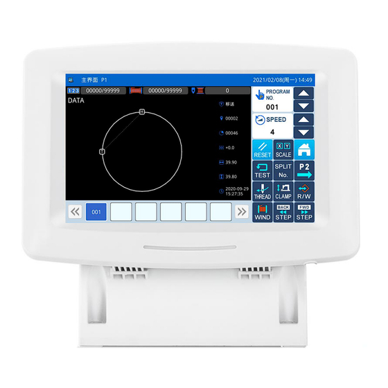
2.3 主界面 P1 说明 功能说明: 序号 功能 内容 加计数器 显示内容为加计数器当前值/设定值。 减计数器 显示内容为减计数器当前值/设定值。 底线计数器报警针数 进行数据设置操作 日期/时钟 显示时间 花样名称 显示当前缝制资料的花样名称。 花样形状 显示当前缝制资料的花样形状。【注】 表示原点位置。 显示最近使用过的花样号码,最多可存储 40 个。 选择一个花样号码键按下后会改变当前缝制资料。 花样号码快捷键 【注】组合缝花样状态下,显示内容为组合缝子花样序号/组合缝花 样个数 花样号码顺序选择键 顺序选择已有的花样形状 速度调整显示区 调整和显示当前花样缝制速度 打开后显示多类目录(参照【2.2.3 实例画面 3】节内容)。 目录键 进入主界面 P2 按下按钮后此时屏幕显示第二主界面 P2 人字缝模板花样设置键... -
Page 26: 花样针数显示
2.3.1 花样针数显示 功能说明: 序号 说明 显示当前外压板位置缝制资料数据类型。 (车缝「SEW」,移送「FEED」,次原点「2HP」,上暂停「USTP」,下暂停「DSTP」,剪线「TRIM」 , 移送速「FEDS」,重启动「ASRT」,压板重「HEVI」,物料厚「ATUM」,跳缝「BAT」,功能 1「FUN1」 ~功能 7「FUN7」,翻压脚「REPF」,结束「END」) 显示当前位置的针数。 显示当前花样的总针数(包括移送、剪线、结束、代码等资料)。 X/Y 移动的距离 花样水平方向的尺寸 花样垂直方向的尺寸 花样形状创建时的时间 2.3.2 速度调整 功能说明: 序号 说明 增加缝纫机速度。 显示当前缝纫速度(200~2700)。 显示为速度值,若点击此图标,可跳转 到标准参数设置界面---快捷操作 降低缝纫机速度。... -
Page 27: 花样号码快捷键操作
2.3.3 花样号码快捷键操作 功能说明: 序号 说明 花样号码快捷键,选择其他的花样号码可以切换缝制花样。(蓝色为当前缝制花样) 花样号码显示翻页键 实例说明: 如图所示, 本例中快捷键列表中共包含有花样号 码 2 个,当前缝制花样号码为 001,如果选择 002 号 花样,则当前缝制花样会切换为第 002 号花样。 如图所示,本示例为选择 002 号花样,则当前缝 制花样会切换为第 002 号花样。... -
Page 28: 花样图形显示
2.3.4 花样图形显示 在主界面 P1 界面,单击花样显示区域,可进入花样预览界面。 功能说明: 序号 说明 花样名称。 花样号码。 花样 X 方向尺寸大小。 花样 Y 方向尺寸大小。 显示当前花样的总针数(包括移送、剪线、结束、代码等资料)。 显示当前花样类型。 花样形状显示。 退出当前界面,返回前一画面。 显示内存剩余空间 花样显示界面循环放大... -
Page 29: 车缝物料厚度设定
2.3.5 车缝物料厚度设定 间歇压脚下降时的高度(最低点位置)是可以修改的,比如出厂时所设置的间歇压脚最低点位置比实 际缝制物料厚度低时,可使用该机能进行修正。 【注】如果当前间歇压脚位置在下时进入该界面,会提示「升高间歇压脚」。 【注】进入物料厚度设置界面后,只有间歇压脚落下时才能够设置。 【注】设置范围是 0.0~8.0mm。 功能说明: 序号 说明 间歇压脚当前高度显示 间歇压脚设置高度显示 间歇压脚高度增加键 间歇压脚会随动,每次增加 0.1mm 间歇压脚高度减小键 间歇压脚会随动,每次减小0.1mm 退出当前界面,返回前一画面。 上下移动缝针。 :针下降 :针上升 按下后中压脚会根据箭头方向移动。 :间歇压脚上升 :间歇压脚落下 保存并退出 外压脚高度设定 二段位压脚设定... -
Page 30: 加计数器设置
2.3.6 加计数器设置 主界面 P1 下按下 进入到加计数器设置界面。 【注】加/减计数器计数方式是由操作设定模式下的「计数器」参数决定的(参照【2.8.6 参数设定表】 中参数说明)。 功能说明: 序号 说明 切换输入设定值和当前值(蓝底白字为选中状态)。 设定值和当前值显示(虚线框表示处于输入状态)。 加计数器有效开关。 复位当前值。 退出计数器设置模式,返回上一级画面。 清除当前输入数值。 数字键盘,用于输入设定值和当前值。 确定设置。 【注】减计数器设置操作同加计数器操作。... -
Page 31: 主界面 P2 说明
2.4 主界面 P2 说明 F G H 功能说明: 序号 功能 内容 对主轴电机安装角度参数进行设置。后面的数字表示为目前主轴的角度 主轴电机安装角度设置 拔线 拔线 剪线 剪线 压脚 压脚 间歇压脚 间歇压脚 松线 松线 翻转压脚 翻转压脚 辅助气阀 1 辅助气阀 1 输出 IO 配置 设置输出 IO 配置参数 输入信号 设置输入信号参数 伸缩压脚 设置伸缩压脚参数 辅助气阀 2 辅助气阀... -
Page 32: 绕线模式
2.4.1 绕线模式 要绕线芯时必须进入到此界面。踏一下外压板开关使外压板降下,然后踏下运转开关时,缝纫机就依 设定的速度转动,而X-Y移动轴不会移动,再次踩踏板,缝纫机就停在上停位置。 【注】绕线芯的动作是由操作设定模式下的「绕线芯」参数的设定而执行。(参照【2.8.6 参数设定表】 中参数说明)... - Page 33 功能说明: 序号 说明 原点检测前是否允许绕线 实际绕线速度设置。 【注】由参数「绕线芯」->「绕线速度设置」决定。 绕线停止方式设置。 【注】由参数「绕线芯」->「绕线器停止方式设置」决定。 定时停止绕线时间设置。 【注】由参数「绕线芯」->「定时停止绕线时间设置」决定。...
-
Page 34: 花样管理
2.5 花样管理 功能说明: 序号 功能 内容 显示已存花样列表 【注 1】如果选择了 VDT 格式花样,会显示提示信息进行花样格式转换。 花样预览列表 【注 2】如果选择花样针数超出范围或者数据损坏,会显示对应的提示信 息不能选择该花样。 花样号码名称 显示已存花样名称。 返回主界面 直接返回主界面 查找键 可以查找花样。 排序键 按照修改时间或号码大小进行排序重新显示花样列表 删除指定花样 删除键 【注】当前缝制花样不能被删除。 另存键 可以将指定花样另存 从内存或者 U 盘中选择一个花样作为当前缝制花样。 读取键 U 盘/内存记忆选择 选择读取内存或者 U 盘花样,切换选择 U 盘或内存 确认键 确定操作。... -
Page 35: 操作说明
2.5.1 操作说明 1、进入花样管理界面 在主界面 P1(或 P2)界面上操作目录键 , 即打开多类目录模式,然后再按下读入图形资料键 。 【注】如果不在原点位置,是无法读取图形资料 的,请先执行回原点操作。 2、选择读取的对象(内存/U 盘) 进入该界面是默认选择内存读取模式(如图), 切换到 U 盘读取模式,U 盘读 可以通过切换键 取模式界面如下图。 【注】 未插入 U 盘时执行上述操作, 会显示 「USB 盘已经拔出」的提示信息。 3、选择图号并确定 选择要缝制的图号然后按下确定键 ,选择成功后会直接返回到主界面。 【注】如果从 U 盘读取花样时,所选择的号码也同样在内存中存在的话,会显示「是否覆盖内存中花 样数据」的提示信息,按照指定信息进行操作即可。 4、其它操作 如果花样比较多,可以通过翻页键 来翻阅画面,并且通过排序键 可以更直观的查阅花样 列表。如果知道花样号码的话,也可以直接指定图号 来读取图形资料。... -
Page 36: 直接读取模式
2.5.2 直接读取模式 1、选择直接读取模式 在花样读取界面下按下直接读取键 , 即进入 到直接读取模式。 【注】直接指定图号读取资料的话,只限用于内 存读取模式。 2、指定图号 1 (例:要读取「01」图号花样) 输入「1」。 下面的键盘会显示出「1」字开头,储存在 内部存储器里的图号依序排列出来。 清除键 可以清除掉输入号码,然后重新 输入。 这时要读取的「1」图号会显示在下段的键 盘中,此时按下 键,操作 成功后返回到主界面显示出「1」图号的图 形资料。 3、英文切换为中文 花样查找时,可以输入中文,切换成中文输 入法模式下输入查找花样。... -
Page 37: 删除花样
2.5.3 删除花样 删除一个花样时需要选择删除键 执行命令, 此时会显示「是否从内存中删除花样数据」的提示信 息 (如果是 U 盘读取模式会显示 「是否删除选中的文 件」提示信息),按照指定信息进行操作即可,但是 不能够删除当前缝制花样。 2.5.4 支持的数据格式 目前可以导入的花样格式有:NSP 格式、B 格式、BA 格式、VDT 格式、EMB 格式、DST 格式、DSB 格式、DSZ 格式、SEW 格式。... -
Page 38: 花样保存
2.6 花样保存 功能说明: 序号 功能 内容 花样名称输入显示 显示输入的花样名称。 花样号码输入显示 显示输入的花样号码。 内存剩余功能 查看内存的剩余量 :存储位置为内存 显示存储位置 :存储位置为 U 盘 输入键盘 用于输入名称或号码。 返回键 返回到上一界面 清除全部输入字符 按下后清除掉全部输入字符。 :选择保留同号花样,保存的花样相同,花样号码不同 保留同号花样 :不选择保留同号花样 选择读取内存或者 U 盘花样,切换选择 U 盘或内存 选择内存/U 盘 确定键 保存当前设置并退出到上一界面... - Page 39 操作说明: 1、进入花样保存界面 在主界面 P1(或 P2)界面上操作目录键 , 即打开多类目录模式,然后再按下写存图形资料键 。 【注】如果不在原点位置,是无法写存图形资料 的,请先执行回原点操作。 2、设定名称和号码 进入该界面是默认选择内存写存模式 (屏幕左上 切换到 U 盘写 方显示 ),可以通过切换键 存模式 在当前界面下直接点击 或 ,可以 切换输入名称或号码。 每按下一次 键,可以清除掉光标左 侧的第一个字符,而按下 键会清除掉全部字符。 输入名称时如果需要大小写输入,可以通过键 实现。 【注】一个花样可以自由选择号码进行存储。花 样文件名改为 “花样名” + “@花样号” + “扩展名.nsp” 的形式。 3、确定保存花样 输入完毕后按下确定键 , 操作成功后直接返 回到主界面。...
-
Page 40: 花样打版
2.7 花样打版 在主界面 P1 界面下,单击菜单键 →花样打 版键 ,进入花样打版界面。 (1) 是否重新输入 如果已输入的资料要更换为新资料,请按下 键(清除掉上一次打版资料,重新打版)。 如果已输入的资料要继续打版的话,请按下 键(继续上一次的打版资料)。 (2) 设定速度 点击界面中四个速度按键, 设置编辑花样数据的缝制 转速: (3) 设定针距 通过 数字键和 键,可以 输入针距,范围为0.1mm~12.7mm。 (4) 图形参数修改 打版、 修改和转换界面都有参数键 , 把相关 的参数集中,便于用户设置。 (5) 确定输入 上述资料设定完成后, 按下 键, 进入花样打 版输入界面。... - Page 42 花样打板界面补充说明 序号 功能 内容 X 相对坐标 显示当前移动的相对坐标 X 值(括号内是十字光标与花样位置差值) Y 相对坐标 显示当前移动的相对坐标 Y 值(括号内是十字光标与花样位置差值) X 绝对坐标 显示当前坐标的 X 值。 Y 绝对坐标 显示当前坐标的 Y 值。 显示设置的针距。 针距 【注】空送针距显示为 12.0mm 速度 显示当前针的速度。 代码 显示当前输入代码。 针数 显示目前机针位置的针数/总针数。 形状点数 当前编辑过程输入的形状点数。 中压脚高度相对值 显示当前中压脚高度相对值 中压脚高度绝对值 显示当前中压脚高度绝对值 输入代码被修改...
- Page 43 序号 功能 内容 退出 返回上一级画面。 目录键 进入目录模式。 :在已经生成的花样上,前进/后退进行寸动。 (在已经生成的花样上进行点移动) 寸动键(点移动键) :在已经生成的花样上,前进/后退进行寸动。 (在已经生成的花样上进行快速点移动) 花样屏幕显示 显示当前打板花样图形...
-
Page 44: 操作设定说明
2.8 操作设定说明 操作设定主要用于设定各个参数,各个参数的说明请参阅【2.8.6 参数设定表】 2.8.1 设定方法 1、进入操作设定的方法: 在主界面 P1(或 P2)界面上操作目录键 , 即打开多类目录模式,然后再按下存储器开关键 。 2、设定模式画面 进入操作设定界面以后,有很多参数项供选择, 可以通过翻页键 来翻阅画面。 3、实例说明: ① 模式选择 选择要设定的参数项按键会显示 「内部参数设定 画面」。这里我们选择「压脚」键。 ② 内部参数设定画面 选择要设定的参数按键会显示「设定值更改画 面」。 (这里按下「003」键。)... - Page 45 ③ 更改参数设定值 按设定值键使参数的设定内容更改后 (这里按下 「ON」键), 再按下确定键 确定。 【注】如按帮助键 ,则显示该设定值的所有文 字,可以看到全文的参数说明。 ④ 更改后的参数设定值检查 回到「内部参数设定」的画面。可检查更改后的 设定值, 按下退出键 离开。 ⑤ 回到模式选择画面 回到「模式选择」画面。因为修改了设定值,会 有「已修改设定」按键出现。 要回主界面P1(或P2)的话请按 键。 要看 「已修改设定」内容,请按下「已修改设定」 键。 查看已修改参数内容 进入密码输入模式 在「模式选择」的画面里按「已修改设定」键, 会进入到密码输入模式, 密码输入正确后方可会进入 到已修改参数设定模式。(关于密码设置内容详见 【2.8.3 参数模式加密说明】)...
- Page 46 进入已修改参数设定模式 该界面下会显示出参数的更改内容。 如要再更改 的话,可在该界面下重新更改(这里可以按下「E-9」 键)。 如果想要选择部分已修改的参数进行还原的 话,可以选择按下标有参数名称的按键(这里可以按 下「脚踏板操作方式」),然后按下「选择还原」按 键,然后按照提示信息内容进行操作即可。 如果想要把更改过的全部设定恢复成出厂设定 的话,请按「还原所有」键,然后按照提示信息内容 进行操作即可。...
-
Page 47: 参数设定分类说明
2.8.2 参数设定分类说明 参数设定分为两种类型:选择型和输入型,如下图所示: 选择型 输入型... -
Page 48: 参数模式加密说明
2.8.3 参数模式加密说明 参数模式下的各个操作入口都可以设定密码,以防止人为的误操作。 1、进入参数加密的方法: 在主界面 P1(或 P2)界面上操作目录键 , 即 打 开 多 类 目 录 模 式 , 然 后 再 按 下 功 能 设 定 键 ,此时会进入到功能设定界面。 在功能设定界面下按下参数加密键 。 2、选择加密项: 如图所示,加密项中包含了全部的参数项,可以 选择一个或多个参数项进行加密(这里选择了「绕线 芯」项)。 :选择状态 :未选择状态 选择了要加密的参数项后,按下确定键 即 可。 此后如果需要设定已加密的参数项参数时,... - Page 49 3、修改密码 在设置新密码界面下,依次按下 、 和 输入框, 并且分别输入当前密码、 新密码和确认密码, 完成新密码设置操作,最后按下 键。 【注】初始密码为厂家 ID,设置一次密码后,「当 前密码」即为上次设置的密码。...
-
Page 50: 参数的还原与备存
2.8.4 参数的还原与备存 可以把更改后的参数设定值保存到 U 盘中,用于以后的还原操作。 1、进入参数还原与备存的方法: 在主界面 P1(或 P2)界面上操作目录键 , 即 打 开 多 类 目 录 模 式 , 然 后 再 按 下 功 能 设 定 键 ,此时会进入到功能设定界面。 在功能设定界面下按下还原备存键 。 2、备存参数 进入还原备存参数界面, 默认情况下是备份用户 参数。 插入 U 盘之后按下确定键 ,一旦操作成功... - Page 51 4、写入用户默认值 选中「写入用户默认值」键,按下确定键 , 系统会提示输入权限 2 密码, 输入成功后则直接执行 此操作。 5、清除用户默认值 成功写入用户默认值后, 「清除用户默认值」键 为可选状态, 选中后按下确定键 即可清除用户默 认值。...
-
Page 52: 默认参数恢复
2.8.5 默认参数恢复 可以把参数设定值恢复为出厂值,另外用户也可以把自己设置好的参数保存起来,用于以后的调用。 1、进入默认参数恢复的方法: 在主界面 P1(或 P2)界面上操作目录键 , 即 打 开 多 类 目 录 模 式 , 然 后 再 按 下 功 能 设 定 键 ,此时会进入到功能设定界面。 在功能设定界面下按下默认参数键 , 会要 求输入密码(初始密码为厂家 ID),密码输入正确 后即进入默认参数模式。 2、调用默认参数 点击相应的默认参数项,按下“机型默认”键即 可重新加载相应的默认参数。 加载完毕后会自动返回到上一级画面。 【注】部分重要参数(如「主轴电机停车角度」等) 不能在该操作中恢复为出厂值。... - Page 53 4、调用用户保存参数 进入该界面的方法同上,观察「自定参数 xx(有 /无)」键显示内容,如果括号内显示为「有」的则 表示该位置上存储了用户参数。 点击该按键, 然后按下 键即可重新加载相应 的参数设定值,操作成功后需要重启。...
-
Page 54: 参数设定表
2.8.6 参数设定表 拨线器 代号 简述 详述 单位 步长 范围 出厂值 类型 0:OFF:拨线器 无效 夹线装置 起针夹线器开关 选择 1:ON:拨线器 有效 0:默认 1:使用电磁铁扫线装置 拨线器类型选择 拨线器类型选择 选择 2:使用气动扫线装置 0:OFF:拨线器 无效 拨线器开关 拨线器(W)输出开关 选择 1:ON:拨线器 有效 拨线器(W)启动时间可 0~998 拨线器启动时间 以设定, 根据剪线时序 毫秒 输入 而设定, 通常无需更改 拨线器(W)保持时间可... - Page 55 0:OFF:关闭 缝制结束时是否剪线 缝制结束时是否剪线 选择 1:ON:打开 剪线后上位置停车角 剪线后上位置停车角 B-10 0~100 度 输入 度修正值 度修正值 松线器 代号 简述 详述 单位 步长 范围 出厂值 类型 缝纫开始时的松 缝纫开始时的松线器打开的 针 输入 线设定 针数设定 切线时的松线同 0~359 松线启动角度 度 输入 步 0:低,打开,无限制 1:中,关闭,5 分钟 2:高,关闭,1 分钟 3:中,打开,无限制 松线器打开模式...
- Page 56 8~17 间歇压脚动作速度 间歇压脚动作速度 输入 0:OFF:关闭 间歇压脚是否随动 间歇压脚是否随动 选择 1:ON:打开 间歇压脚降低的针 D-16 间歇压脚降低的针数 输入 数 间歇压脚降低的高 D-17 x0.1mm 0~30 间歇压脚降低的高度 输入 度 压板 代号 简述 详述 单位 步长 范围 出厂值 类型 0:返回到起缝点 以后, 压脚再上升 1:缝制结束后压 缝制结束后压脚 缝制结束后压脚状态 脚立即上升 选择 上升方式 2:先回到起缝点, 等到踩踏板后压...
- Page 57 动车缝 4:左右压脚->间歇压脚的 2 段压脚。单踏板 1 档为 左右压脚,2 档为间歇压 脚,3 档控制启动。三踏 板中间踏板控制间歇压脚 升降 5:左右交替的 2 段压脚。 压脚踏板控制每次缝制时 2 段压脚左右顺序互换 6:前进\后退踏板。压脚踏 板控制左右压脚依次抬 起,启动踏板控制左右压 脚顺序落下,全落下后再 踩启动开始车缝 7:踏入 2 次的 2 段压脚。 单踏板控制电机压脚在中 间位置、下降、启动三个 位置切换,收回时压脚上 升。双踏板气动压脚动作 同模式 2 8:标准三踏板,压脚踏板 控制电机压脚下降到二段 位高度,中间踏板控制电 机压脚下降到位,启动踏 板启动车缝 9:三踏板带原点检测。中 间踏板专用原点检测,压...
- Page 58 0:压板压下 断缝程序时的压脚 中途停止时压板状态 选择 1:压板抬起 动作 0:无效 1:气动规格的阀 门输出反转 气动压框输出极性 2:由于 2 个定位 气动压框输出极性反转 选择 反转 阀门相对应, 同时 输出反转阀门输 出 0:缝制完成后压 缝纫结束时的压脚 板自动抬起 自动加工完成后压板抬起 选择 1:缝制完成后压 动作 板不抬起 -1:轻 1:标准 压框重量选择 压框重量选择 选择 0:重 0:AIR:气动 1:MAG:电磁铁 压板类型选择 压板类型选择 选择 2:MOTOR:电机 0:OFF:不能缝纫...
- Page 59 支持翻转、伸缩压脚 0-无 1-翻转压脚(F1 压脚) 2-伸缩压脚(停车) 0~255 翻转装置 输入 3-F2 压脚 4-K 压脚 5-伸缩压脚(不停车) 0:OFF:不动作 1:MRH:先移出再 回原点时伸缩压脚 回原点时伸缩压脚动作 回原点 选择 动作 2:HRM:先回原点 再移出 x0.01s 0~255 伸缩压脚伸出延时 伸缩压脚伸出延时 输入 x0.01s 0~255 伸缩压脚上升延时 伸缩压脚上升延时 输入 x0.01s 0~255 伸缩压脚下降延时 伸缩压脚下降延时 输入 激光切割 代号 简述 详述...
- Page 60 缝制中断时的机针 1:机针上定位 停止位置 0:自动剪线 暂停时的切线动作 暂停时自动剪线 选择 1:不剪线 0:复位后向缝制 开始点移动 1:不进行原点复 暂停时的复位模式 暂停时的复位模式 选择 归, 在缝制轨迹上 倒进移动至缝制 开始点 0:DWN:压板压下 暂停时压板动作 暂停时压板动作 选择 1:UP:压板抬起 0:常关型 暂停开关类型 暂停开关类型 选择 1:常开型 0:常关型 安全开关类型 安全开关类型 选择 1:常开型 断线检出器 代号 简述 详述 单位 步长 范围 出厂值...
- Page 61 踏脚开关第 1 档 为高速送布 1:测试送布与缝 制时的速度相同 0:-10:提前 1:0:标准 -10~10 改变全部的送布同步 输入 2:10:延迟 每数字对应 8 度 0:-10:提前 改变缝纫开始第 1 针 1:0:标准 -10~10 输入 的送布同步 2:10:延迟 每数字对应 8 度 0:-10:提前 改变缝纫开始第 2 针 1:0:标准 -10~10 输入 的送布同步 2:10:延迟 每数字对应 8 度 0:-10:提前 改变缝纫开始第...
- Page 62 0:薄 1:中 缝纫类型选择 缝纫类型选择 选择 2:厚 0~255 薄物料厚度 薄物料厚度 输入 0~255 中物料厚度 中物料厚度 输入 0~255 厚物料厚度 厚物料厚度 输入 0:抬起停止 试缝方式 试缝方式 选择 1:抬起继续移动 0:LINE:直线移动 打版和图形修改中两 J-10 1:PAT:跟随针步移 快速移动方式(打版) 选择 点移动方式 动 J-15 动框增益曲线 动框增益曲线 输入 J-16 X 轴刚性微调 X 轴刚性微调 -15~ 15 输入...
- Page 63 缝纫结束前 2 针速度 倒数第 2 针给定速度 x100RPM 4~27 输入 x100RPM 2~30 第一针启动速度 第一针启动速度 输入 x100RPM 2~30 第二针启动速度 第二针启动速度 输入 x100RPM 2~30 第三针启动速度 第三针启动速度 输入 x100RPM 2~30 第四针启动速度 第四针启动速度 输入 x100RPM 2~30 第五针启动速度 第五针启动速度 输入 0:不加固 1:在第一针进行 起缝加固方式 起缝加固方式 缩缝 选择 2:在前几针进行...
- Page 64 0:OFF:范围保护关闭 取消范围保护 取消范围保护 选择 1:ON:范围保护打开 0:OFF:关闭 禁止 X 方向移动 禁止 X 方向移动 选择 1:ON:打开 电机 代号 简述 详述 单位 步长 范围 出厂值 类型 0:OFF:无效 1:ON:缝纫机马达锁定 贯穿力增强动作 贯穿力增强动作 选择 时,贯穿力增强动作 进行 0~50 倒转针上升的角度 上死点角度设定 度 输入 0:正向 x 电机转向 x 电机转向 选择...
- Page 65 0:标准 1:反转 向原点位置和缝纫 平时原点检索/原点复 2:Y 轴到 X 轴 开始点位置的移动 选择 位线路选择 3:X 轴到 Y 轴 路线 4:XY 轴同步 0:不进行原点检索动 作 花样切换时原点动 1:不进行原点检索动 花样切换时原点动作 选择 作 作,但经过区域中心 2:进行原点检索动作 0:踩踏板起动后,再向 新花样起点移动 花样切换时起点移 花样切换时的原点 选择 1:切换花样的同时,移 动模式 动作 动到新花样的起点 0:OFF:不回原点 加电时回原点 加电时回原点 选择 1:ON:回原点...
- Page 66 0:清除 导入花样时加计 导入花样时加计数器 选择 1:保留 数器值是否保留 值是否保留 0:清除 导入花样时减计 导入花样时减计数器值是 选择 1:保留 数器值是否保留 否保留 0:清除 电源重开时消除 电源重开时消除计算器 选择 1:保留 计算器 0:OFF:允许修改 禁止加算器(UP) 禁止加算器(UP)被修改 选择 1:ON:禁止修改 被修改 0:OFF:允许修改 禁止减算器(DN) 禁止减算器(DN)被修改 选择 1:ON:禁止修改 被修改 0:OFF:停止缝纫 到达加算器(UP) 到达加算器(UP)设定值 设定值时缝纫机 选择 1:ON:可继续缝纫 时缝纫机的操作 的操作 0:OFF:停止缝纫...
- Page 67 0:ICN:图标 设置检测模式和功能 按键显示风格 选择 1:TXT:文本 模式下按键显示风格 0:ICN:图标 修改和转换按键显 修改和转换按键 选择 1:TXT:文本 示风格 显示风格 0:OFF:关闭 S-11 大针数花样支持 大针数花样支持 选择 1:ON:打开 矢量图形转换针距 矢量图形转换针距设 S-12 x0.1mm 10~127 输入 设置 置 0:OFF:关闭 S-13 花样缝纫进度描绘 花样缝纫进度描绘 选择 1:ON:打开 0:OFF:关闭 花样切换锁显示 和模板识别功能配合 S-14 选择 1:ON:打开 设定 使用...
- Page 68 0:OFF:关闭 曲线角点快捷键 曲线角点快捷键 选择 1:ON:打开 0:0:保持 打版空送后还原 设置打版空送后还原 选择 1:1:直线 车缝的风格 车缝的风格 0:OFF:否 打版后针法还原 打版后针法还原 选择 1:ON:是 0:0:面积 放大方法 花样打版放大方法 选择 1:1:长宽 0:0:否 是否显示落针点 是否显示落针点 选择 1:1:是 多重缝、偏移缝、倒 0:0:针迹 花样转换选择 缝、曲折缝、首尾交 T-10 选择 方法 换等修改位置选择 1:1:要素 方法 0:0:百分比 T-11 缩放单位 缩放单位...
- Page 69 1:ON:使能 定 0:OFF:关闭 仅针对直线,1mm 距 T-25 小针距形状融合 离以内形状点会融合 选择 1:ON:打开 上一条要素 0:OFF:关闭 依据花样轮廓大 图形修改中依据花样 T-26 选择 1:ON:打开 小自动放大 轮廓大小自动放大 0:OFF:关闭 暂停码扩展气阀 T-27 暂停码扩展气阀功能 选择 1:ON:打开 功能 0:0:选择一针 中压脚高度修改 T-28 中压脚高度修改方式 选择 1:1:选择一段 方式 0:0:简易 T-29 段移动方式 段移动方式 选择 1:1:复杂 0:0:单选(绝对和相 T-30 对方式修改) 点移动选择方式...
- Page 70 1:ON:是 言选择 选择 0:0:精简 U-12 DXF 文件转换方法 DXF 文件转换方法 选择 1:1:复杂 0:OFF:关闭 U-13 导出其它格式 导出其它格式 选择 1:ON:打开 维修保养 步 代号 简述 详述 单位 范围 出厂值 类型 长 x1000 针 0~9999 更换机针剩余值 更换机针剩余值 输入 x1000 针 0~9999 更换机针设定值 更换机针设定值 输入 0~9999 清扫时间剩余值...
- Page 71 代号 简述 详述 单位 步长 范围 出厂值 类型 0:OFF:关闭 自动换梭开关 自动换梭开关 选择 1:ON:打开 0:0:底线报警后手 动换梭 换梭方式 换梭方式 选择 1:1:底线报警时自 动换梭 0:0:手动启动 换梭后启动方式 换梭后启动方式 选择 1:1:自动启动 0:0:放回梭盘 空梭芯处理方式 空梭芯处理方式 选择 1:1:放收纳盒 0:0:梭盘侧 换梭臂停车位置 换梭臂停车位置 选择 1:1:机头侧 换梭臂到机头位 换梭臂到机头位置微 -100~100 输入 置微调 调...
-
Page 72: 检测模式说明
2.9 检测模式说明 在主界面 P1(或 P2)界面上操作目录键 , 即 打 开 多 类 目 录 模 式 , 然 后 再 按 下 检 测 模 式 键 ,即进入到检测模式。 功能说明: 序号 功能 内容 液晶检测 用于检测液晶显示。 触摸屏校正 用于校正触摸屏。 输入信号检测 用于检测各类开关、传感器等输入信号。 速度检测 用于检测主轴马达转速。 输出信号检测 用于检测各类压脚、剪线等输出信号。... - Page 73 多功能 IO 多功能 IO...
-
Page 74: 液晶检测
2.9.1 液晶检测 功能说明: 检测模式界面下按下液晶检测按键 , 进入 液晶检测功能, 点击除退出键 以外的位置, 液晶 会依次显示白、黑、红、绿、蓝五种颜色,用于判定 液晶是否存在失色。 按下退出键 返回到上一级画面。 2.9.2 触摸屏校正 功能说明: 检测模式界面下按下触摸屏校正键 , 此时 会显示「输入用户 ID」界面,见右图,输入 ID 后按 下确定键 进入触摸屏校正功能。 需要进行 5 点的校正, 最好采用触摸笔一类工具 点击画面中的十字光标, 校正结束后会显示提示信息 显示本次操作是否成功。 【注】 校正过程中请务必按照十字光标指示位置进行 确定,否则会导致校正结束后无法正常使用触摸屏。... -
Page 75: 输入信号检测
2.9.3 输入信号检测 功能说明: 检测模式界面下按下输入信号检测按键 , 进入输入信号检测功能。 ON:表示开启 OFF:表示关闭 输入信号种类: 启动开关(踏板) 压脚开关(踏板) 暂停开关 断线检测 X 马达传感器 Y 马达传感器 中压脚原点 安全开关 外部输入 1(PORG) 外部输入 2(PSENS) 外部输入 3(CORG) 外部输入 4(CSENS) 外部输入 5(AORG) 三联脚踏板 按下退出键 返回到上一级画面。 单击可编程 IO 键 , 进入输入信号配置 界面,可进行输入信号配置操作。... - Page 76 举例说明: 单击输入 3(IN3) ,进入自定义输入 信号界面, 可通过单击 按钮选择输入信号, 如下: 1)无 2)找原点 3)启动缝制 4)缝制速度加 5)缝制速度减 6)气压检测 7)断线检测 8)特殊输入功能 1~9 单击确定键 确定并返回输入信号配置界面, 单击取消键 取消操作并返回输入信号配置界面。 单击详细设定键 ,进入自定输入 信号界面,可设置如下参数: 1)输入讯号开关状态设定(逻辑): 正常/反相 默认值:正常 2)交替开关设定时,开关状态保留至下次: 正常/交替开关 默认值:正常...
-
Page 77: 主轴转速检测
2.9.4 主轴转速检测 功能说明: 检测模式界面下按下速度检测按键 , 进入 主轴转速检测功能。 通过 和 可以设置主轴马达目标转速, 通过 和 可以设置主轴马达正转或反转,按 下运转键 后, 主轴马达会以设定的转速旋转。 此 时,实际测得的转速会显示在实际转速输入栏。 按下停止键 ,则机器停止运转。 按下退出键 返回到上一级画面。... -
Page 78: 输出信号检测
2.9.5 输出信号检测 功能说明: 检测模式界面下按下输出信号检测按键 , 进入输出信号检测功能。 在该界面下按下输出信号按键, 就可以检测电磁 铁等输出信号的输出状态。 输出信号种类: 拔线 剪线 压脚 间歇压脚 松线 夹线器 T2 辅助气阀 1~8 按下退出键 返回到上一级画面。 【注】缝纫机会有实际动作。 自定输出信号: 单击[可编程 IO]键,进入自定输出信号界面,可 进行自定输出信号操作。 举例: 单击“气阀 1(V1)”键,进入自定义输出信号 界面,可通过单击 按钮选择输出信号,如 下:... - Page 79 1)无 2)辅助压框 20)剪线 3)翻转压脚 21)松线 4)主轴运行 22)拨线 5)缝制完成 23)中压脚 6)错误状态 24)外压框 7)找原点 25)缝前插刀 8)次原点 26)缝后吹气 9)中途停止 27)机针冷却 10)侧滑压脚伸缩 28)断线输出 11)侧滑压脚升降 29)急停输出 12)抓线 30)记号笔 13)功能 1~9 31)激光定位灯-左 14)功能 A/B/C 32)激光定位灯-右 15)回原点压框落下 33)辅助夹具 1~9 16)回次原点压框落下 34)启动自动换梭 17)激光 35)工作中指示灯 18)激光吸气 36)待机指示灯 19)激光升降 37)特殊压脚功能 1~7 单击确定键...
-
Page 80: 连续运转
2.9.6 连续运转 功能说明: 检测模式界面下按下连续运转按键 , 进入 连续运转设定功能。 点击动作间隔输入栏或收针原点检测输入栏, 通 过数字键盘输入想要设定的数值, 按下确定键 返 回到上一级画面。 可以通过踏板或者原点两种老化启动方式, 设置 完毕后返回到主界面 P1(或 P2),踩下脚踏板或者 按下回原点按键使缝纫机运转起来, 即进入到连续运 转模式 2.9.7 XY 马达原点检测 功能说明: 检 测 模 式 界 面 下 按 下 XY 马 达 原 点 检 测 按 键 ,进入... -
Page 81: 主轴马达安装角度设置
2.9.8 主轴马达安装角度设置 功能说明: 检测模式界面下按下主轴马达安装角度设置按 键 ,进入主轴马达安装角度设置功能。 1)针杆最高校正 在当前界面下拆下主轴马达, 旋转手轮将缝纫机 针杆摇到最高点,重新装好主轴马达,确认显示的电 气值在 0-30 度或 330-360 度范围内, 然后按下确定键 ;否则拆下主轴重复以上动作。 2)停车位校正 在当前界面下拆下主轴马达, 旋转手轮将缝纫机 针杆摇到停车位置,重新装好主轴马达,确认显示的 电气值在 23-83 度范围内,然后按下确定键 ;否 则拆下主轴重复以上动作。 2.9.9 中压脚检测 功能说明: 检测模式界面下按下中压脚检测按键 , 进 入中压脚检测功能。 :降低中压脚 :提升中压脚 :切换中压脚位置... -
Page 82: 功能设定说明
2.10 功能设定说明 在主界面 P1(或 P2)界面上操作目录键 , 即 打 开 多 类 目 录 模 式 , 然 后 再 按 下 功 能 设 定 键 ,即进入到功能设定模式。... - Page 83 功能设定界面: 功能说明: 序号 功能 内容 软件版本 查询系统软件版本。 循环程序 编辑组合花样。 面板设定 提供背光、按键锁、亮度等显示设定。 用户可根据根据自己常用的功能,编辑此快捷键,显示在主页面上,方便用 功能快捷键 户操作便捷。 图形复制:内存与 U 盘之间传输拷贝花样文件。 格式化:格式化 U 盘、内存和花样号码快捷键。 图形管理 批量转换:进入花样格式批量转换模式,把非标准的花样格式都修改为标注 花样格式。注:标准花样格式为 nsp 格式。 参数设定值保存到 U 盘中,用于以后的还原操作。 还原备存 默认参数 提供默认参数的恢复和自定义读写功能。 参数加密 参数模式下的各个操作入口设定密码。 分期密码 提供用户分期密码功能。 日期时间 设置日期和时钟。 报警记录:查看报警统计信息。 记录 运转记录:查看机器运转信息。 软件升级...
-
Page 84: 软件版本查询模式
2.10.1 软件版本查询模式 功能设定界面中按下版本查询键 , 即进入 版本查询模式。 键可以把软件版本导出到 U 盘根目录 按下 下,文件名为 version.png。 2.10.2 循环程序 功能设定界面中按下图形连接键 ,即进入图形连接模式。图形连接模式主要用于创建和编辑组 合花样,也就是在已有的花样基础上进行组合编辑,构成组合花样的文件称为子花样文件。 功能说明: 序号 说明 页数显示 组合花样名称显示 读取组合花样 存储组合花样 子花样文件显示 退出,返回上一级画面 翻页 从内存读取已有的花样添加到组合花样中 删除组合花样中的子花样文件 取消组合花样 确定当前操作... - Page 85 操作说明: 1、 选择一个子文件 点击按键 , 进入到读取模式, 选择想要添加 的花样文件(这里选择了 001 号花样),按下确定键 确定选择。 【注】组合花样中添加文件必须按前后顺序添加。 2、 继续添加子文件 同之前的操作,继续添加子花样(这里选择继续 添加了 002 号花样)。 如果想要删除掉其中一个子花样文件, 点击想要 删除的子花样文件图号,然后再按下删除键 即 可。 3、 保存组合花样文件 按下保存键 ,进入到组合花样保存模式。 为组合花样起好名字之后, 按下确定键 确认 保存。 该界面下其他操作参照 【2.6 花样保存】 内容。...
- Page 86 4、 返回主界面 当组合花样编辑结束后, 按下确定键 返回到 主界面。 如图所示, 组合花样缝制界面与普通花样缝制界 面有一些区别: ① 号码区域后面显示了组合花样名称,而名称 区域显示了组合花样中当前子花样文件的名称。 【注】如果组合花样没有名称,则什么也不显示。 ② 原来的花样号码快捷键区域显示内容为组合 花样所包含的子花样文件。 可以直接点击子花样文件 图号,这样的话就会从该花样开始进行缝制。 5、 取消组合花样缝制 如果想要取消掉组合花样缝制, 需要再次进入图 形连接模式, 然后点击按键 , 然后确定键 返 回即可。 6、 读取组合花样文件 在图形连接模式界面下,如果存在组合花样资料 显示时点击按键 ,此时会显示「请清除当前 的合并资料」提示信息,点击按键 之后会清 除掉当前组合花样显示资料。 再次点击按键 就可以进入到混合图形读取 界面,选择想要缝制或编辑的组合花样文件即可。...
-
Page 87: 面板设定
2.10.3 面板设定 功能设定界面中按下面板设定键 , 即进入 显示设定模式,该界面下可以调整有关显示、操作的 一些设定。 1、自动关闭背光 设定的时间一到,屏幕背光会自动关闭。 设定范围:1~9 分钟 出厂设定值:「无效」 解除方法:在背光关闭期间,只要在面板的任何 地方按一下就会点亮屏幕。 2、 接触按键锁 接触按键锁为「有效」时,即进入防止误操作状态, 所有按键成无作用状态(显示为灰色),确定键 操作之后会直接返回到主界面 P1。 出厂设定值:「无效」 解除方法:按住主界面 P1 的标题栏 5 秒钟以上,等 「哔」声响后即完成解除。(解除以后,解除按键锁 机能会设定成「无效」) 3、 主界面速度设置方式 分档位和真值两项,出厂设定值:「档位」 4、 主界面花样显示设定 设定范围:0~6(0:黑色,1:青色,2:红色, 3:绿色,4:蓝色,5:紫色,6:黄色) 出厂设定值:0:黑色 5、 调节 LED 灯亮度 调节范围:0~100 出厂设定值:50... -
Page 88: 功能快捷键
2.10.4 功能快捷键 快捷键功能用于设置主界面右下角四个功能键, 用户可自行设置常用的功能键。 按下 快捷功能键进入快捷功能设置。 分别 设置原点、图形缩放、穿线、 中压脚高度、图形复制、 绕线六个功能的常用功能。 图形打板设置: 按下当前需更改为图形打版的快捷键, 进入快捷 键设置,选取功能后显示 ,按下 确认 键,保存并退出。... -
Page 89: 图形管理
2.10.5 图形管理 功能设定界面中按下图形管理键 , 即打开 图形管理分组,可对以下功能进行设置: 1)图形传输 2)格式化 3)批量转换... -
Page 90: 数据传输模式
2.10.5.1 数据传输模式 功能设定界面下按下数据传输键 ,即进入数据传输模式。 提供两种传输方式:「内存复制到 U 盘」和「U 盘复制到内存」。 功能说明: 序号 说明 花样列表 翻页查询 退出,返回上一级画面 使花样按照花样号排序 删除选择的花样 花样另存 选择全部花样 选择读取内存或者 U 盘花样 :U 盘读取模式使能,此时内存读取模式禁止 :内存读取模式使能,此时 U 盘读取模式禁止 确定操作 操作说明:... - Page 91 1、复制模式选择 默认进入该界面是内存花样复制到 U 盘模式, 可以通过 键切换复制模式。 2、选择文件 在花样列表中选择要复制的花样文件 (本例中选 择了 001、002 号花样),如果花样较多可以通过翻 页键 来翻阅画面。 如果想要复制全部花样按下 键, 删除花样按 下 键。 3、确定复制 选择好了花样文件之后, 按下确定键 , 此时 会显示「是否拷贝指定的花样数据」的提示信息,按 执行复制操作。 如果是从内存复制到 U 下确定键 盘,会在 U 盘根目录下自动创建「DH_PAT」目录, 花样文件会拷贝到该目录下。 【注】复制时内存和 U 盘里如有相同的图号时, 会被新资料盖写。...
-
Page 92: 格式化模式
2.10.5.2 格式化模式 功能设定界面中按下格式化键 , 即进入格 式化模式。 该界面下提供 4 种格式化方式:格式化 U 盘、 格式化全部内存(花样) 、自定义格式化内存 (花样) 和格式化快捷键(花样列表)。 1、格式化 USB 说明: 按下「USB」按键之后会把 USB 内全部文件删除掉,需要备份资料的话请提前做好备份。 2、格式化内存说明: 按下「内存」按键之后会把内存中全部花样格式化掉。 【注】执行内存格式化命令之后,按下退出键 退出时,会显示「内存中没有花样」的提示信息,确定 键 操作后会自动加载出厂花样。 3、自定义格式化说明: 按下「自定义」按键之后,会进入到自定义格式 化内存花样界面。 该界面下提供了全部花样列表, 可以选择性的删 除花样。 【注】当前缝制花样不能删除。 4、快捷键格式化说明: 按下「快捷键」按键之后,会清除掉花样号码快捷键的内容。 【注】执行快捷键格式化命令之后,按下退出键 退出时,会显示「花样列表(快捷键)为空」的提示 信息,确定键 操作后会把当前花样号码导入到快捷键中。... -
Page 93: 花样格式批量转换
2.10.5.3 花样格式批量转换 花样批量转换功能, 用于旧版软件升级后的花样 继续使用。 花样号为默认空余号,可以手动分配花样号。 默认为全选中,左边花样名前面的 x 表示选中, 空表示不选。 默认删除原始花样,如果想保留,选下方的“保 留原始花样”。 2.10.6 还原备存模式 功能设定界面中按下还原备存键 , 即进入 还原备存模式。 可以把更改后的参数设定值保存到 U 盘中,用 于以后的还原操作。 详细内容参照【2.8.4 参数的还原与备存】节。 2.10.7 默认参数模式 功能设定界面中按下默认参数键 , 会要求 输入密码(初始密码为厂家 ID),密码输入正确后 即进入默认参数模式。 主要用于恢复出厂参数, 以及用户自定义保存当 前参数设定值,用于以后的调用。 详细内容参照【2.8.5 默认参数恢复】节。... -
Page 94: 参数加密
2.10.8 参数加密 在功能设定界面下按下参数加密键 , 进入 参数加密模式,主要用于对指定参数进行加密和管 理。 详细内容参照【2.8.3 参数模式加密说明】节。... -
Page 95: 密码模式
2.10.9 密码模式 功能设定界面中按下密码管理键 , 进入密 码管理模式,主要用于用户分期密码的设置和管理。 可以最多设置 10 个不同的密码发作日期。 ②系统可以显示厂家设置的密码信息。 1、 输入板号 按下「板号」键,进入输入板号界面,板号为四 位,范围 000000000000000~999999999999999,可 用于厂家的密码管理。 输入板号后并按下 键完成 操作并返回上界面。(这里输入板号为 0001) 2、 确定系统时钟 按下「时钟」键,会进入设置系统日期和时间界 面, 如需要修改系统时钟, 请在修改时钟后按下 键完成操作(参照【2.10.14 日期与时间设置模式】 节内容),否则按下 键退出即可。 3、 输入超级密码 按下 「超级密码」 键, 会进入输入超级密码界面。... - Page 96 最多可以输入 15 位总密码,画面以「·」号显 示, 按 键确认后, 会要求再次输入密码进行确认。 如果两次输入密码不一致,则要求重新输入超级密 码。两次输入密码一致后,按 键保存并退出。 4、 输入分期有效日期和密码 按下 「密码-1」 键, 会要求输入第一个有效日期。 有效日期是指第一次密码发作的时间, 该日期不 可早于系统日期。 选择合适的日期后按下 键完成操作, 此时会 进入到输入密码界面。...
- Page 97 分期密码输入方式与输入超级密码的方式相同, 确认密码完成之后按下 键保存退出。 5、 选择继续输入分期密码 如果需要输入下一个有效日期和密码, 具体操作 同上。最多可输入 10 个有效日期和密码。 【注】下一个有效日期必须大于上一个有效日期。 6、 保存密码 输入完所需要的密码后, 按下 键保存设置的 全部信息, 如果密码保存成功会显示 「密码保存成功」 的提示信息。 确定保存之后会返回到上一级画面。 【注】 只有至少设置 了一个分期密 码后才会显 示 键。...
- Page 98 7、 保存密码信息 进入密码统计界面,显示板号和密码、分期密码 和日期,插入 U 盘后,按下输出键 ,输入新 名称,按下回车键 保存,密码保存成功后,会显 示密码信息保存成功的提示信息。...
- Page 99 8、 主动清除密码 主动清除密码是指在密码发作之前清除密码。 进入密码显示界面的方法与进入密码设置的方 法相同。 在正确输入厂家 ID 之后,显示如右图所示,系 统显示出当前时钟和各个分期密码的发作日期。 按下 键则会提示输入当前密码,清除密码依 照从前往后的顺序。 此时,输入两个密码有效。当输入密码为当前提 示密码时,则清除当前密码;当输入密码为超级密码 时,则清除所有密码,即机器不再有密码。当清除的 为当前密码时, 如果后面无密码, 则机器不再有密码。 按下 键完成操作。 经解密的密码显示为红色,如右图所示。如果全 部密码被解密则自动退出,返回到上一级界面。 9、 密码发作时清除密码 如果系统已经设置密码并且未解除, 则使用至设 定密码有效日期时会遇到密码发作, 此时要求用户必 须输入有效密码才能使机器继续正常运行。 有效密码包括当前提示的密码和总密码。 当输入 密码为当前提示密码时,则清除当前密码;当输入密 码为总密码时, 则清除所有密码, 即机器不再有密码。 当输入的为当前密码时,如果后面没有密码,则机器 不再有密码;如果后面还有密码,则按照设置日期生 效。...
-
Page 100: 日期与时间设置模式
2.10.10 日期与时间设置模式 功能设定界面中按下日期时间设置键 , 可 以进入日期与时间设置模式。 1、 日期设置方法: 点击日历中的「年份」(这里为 2020),会显 示出左右两个箭头,用于调节年分大小。 点击日历中的「月份」(这里为三月),会弹出 1~12 月的选择菜单,选择合适的月份即可。 年份和月份设置后均会刷新日历显示, 显示该年 月的正确月历内容。 也可以通过 键和 键前后查询月历内容。 在日历中点击日期,就可以设置好日期了。 【注】 设置日期必须在月历中点击了日期才可以设置 成功,不能仅修改年份和月份。 2、 时间设置方法: 默认情况下进入该界面都是先设置小时, 可以通 过「小时」键切换成设置分钟(此时「小时」键显示 内容会改变为「分钟」),然后通过左右箭头修改内 容即可。 也可以点击小时或分钟显示区域来切换修改小 时/分钟修改方式。 日期或时间修改完毕后,按下 键保存并退 出。... - Page 101 3、 禁止修改系统时间 一旦设置了分期密码,则禁止修改系统时间,清 除全部密码后可以解除禁制。...
-
Page 102: 报警记录模式
2.10.11 报警记录模式 功能设定界面中按下记录键 , 即打开记录 分组,可查看以下记录: 1)报警记录 2)运转记录 2.10.11.1 报警记录模式 功能设定界面中按下报警记录键 , 可以进 入报警记录模式。 报警记录模式下显示了系统最近发生的报警内 容,序号越小表示该报警信息发生的时间越新。 按下数字键 后,会显示报错信息和解决措 施。 按下“数据统计查看”键 ,可进入报警记录 统计界面。... -
Page 103: 运转记录模式
2.10.11.2 运转记录模式 功能设定界面中按下运转记录键 , 会要求 输入厂家 ID,输入正确后可以进入运转记录模式。 ① 累积运转时间:记录机器缝纫时间总和 ② 累积缝纫件数:记录缝纫花样总件数 ③ 累积上电时间:记录机器上电时间总和 ④ 累积缝纫计数:记录机器缝纫针数总和 另外点击「清除」键可以清除掉该项计数值。 【注】如果清除了累积缝纫件数,也同时会把主界面 辅助信息栏的「累积计数」清零。 运转记录模式界面按下[开机时间]键 ,即可查看历史开机时间列表。 使用翻页键 进行翻页,单击清除键 可删除开机记录。... -
Page 104: 软件升级
2.10.12 软件升级 功能设定界面中按下升级键 , 会要求输入 厂家 ID,输入正确后可以进入软件升级模式。 升级软件需要放在 U 盘「update」目录下。 首先单击[选择目录]键 ,选择需升级 软件所在目录。 选中后单击确认键 ,将返回软件升级界面, 并显示目录中全部可升级软件信息。 然后单击[详细设置]键 ,选择需升级 软件明细。 单击确认键 , 将返回软件升级界面, 再次按 下确认键 ,即可升级相应软件。... -
Page 105: 系统参数
单击[版本]键 ,可查询当前面板软件 版本。 2.10.13 系统参数 功能设定界面中按下系统参数键 , 可以进 入系统参数设置模式。 在 系 统 参 数 设 置 界 面 , 单 击 [ 参 数 设 置 ] 键 ,可以进入系统参数设置界面并进行相关操 作。 在 系 统 参 数 设 置 界 面 , 单 击 [TD 参 数 ] 键 ,可以进入... -
Page 106: 字母绣编辑
在 系 统 参 数 设 置 界 面 , 单 击 [ 参 数 升 级 ] 键 ,可以进入参数升级设置界面并进行相关操 作。 2.11 字母绣编辑 在主界面 P1(或 P2)界面上操作目录键 , 即打开多类目录模式,然后再按下字母绣编辑键 ,即进入到字母绣设置模式。 【注】参数「特殊」->「字母绣功能使能」可以关闭 字母绣编辑功能,关闭后不显示该图标。... -
Page 107: 字母绣参数设置说明
2.11.1 字母绣参数设置说明 功能说明: 序号 功能 内容 输入字符,最多可以输入 20 个字符。 字符输入 支持 28 种字体。 选择字体 排列方式 提供水平、垂直、上玄弧和下玄弧排列方式。 字符间距 设置相邻字符间距。 平包针密度 设置平包针密度,设定值越大平包针越密。 设置字符的高度缩放,范围为 50~200。 高度缩放 设置字符的宽度缩放,范围为 50~200。 宽度缩放 排列方式为直线(水平、垂直)时,该按键显示内容为旋转,用于设置字 符旋转角度; 旋转/跟随(不跟随) 排列方式为圆弧(上玄弧、下玄弧)时,该按键显示内容为跟随(不跟随) , 用于设置字符是否跟随圆弧旋转。 剪线/不剪线 确定是否自动插入剪线。 返回主界面 退出,返回到主界面。 确定 确定操作,会进入到字母绣花样调整界面。... - Page 108 操作说明 1、字符输入 按下「输入」键,进入字符输入界面,需要至少 输入一个字符,最多可输入 20 个字符,按下 键 保存并退出。 2、选择字体 按下「字体」键,进入字体选择界面,提供 28 种不同的字体,直接输入 1-28 之间的数字进行选择, 按下 键保存并退出。 该界面下提供每种字体的形状显示。 3、排列方式 按下「排列」键,进入排列方式设置界面,提供 水平直线、竖直直线、上玄弧、下玄弧 4 种字符排列 方式,按下 键保存并退出。 4、 字符间距 按下「间距」键,进入字符间距设置界面,水平 排列时,表示相邻字符轮廓之间的水平间距。 竖直排列时,表示相邻字符轮廓之间的垂直间 距。 圆弧排列时, 表示相邻字符轮廓之间在圆弧上的 距离。 范围为 0~99.9mm。...
- Page 109 5、 包针密度 按下「密度」键,进入平包针密度设置界面,设 置的平包针密度在 50~200 之间。 6、 字母高度缩放 按下「高度」键,进入字母高度设置界面,设置 字符的高度缩放,范围为 50~200。 7、 字母宽度缩放 按下「宽度」键,进入字母宽度设置界面,设置 字符的宽度缩放,范围为 50~200。 8、 旋转角度设定 排列方式为水平排列或者竖直排列时, 可以设置 字母旋转角度,按下「旋转」键,进入旋转角度设置 界面。 旋转方向为逆时针旋转,范围为 0°~359°。 【注】排列方式为上玄弧或下玄弧时,该按键功能为 设置是否跟随圆弧旋转。 排列方式为上玄弧或下玄弧时, 可以设置字母的 角度是否跟随圆弧旋转。按下「跟随」键,可以切换 到「不跟随」,反之亦然。 【注】排列方式为水平排列或者竖直排列时,该按键 功能为设置旋转角度。...
- Page 110 9、 是否自动添加剪线 默认情况下是自动添加剪线, 也就是在字母绣花 样的车缝和空送连接处,以及缝纫最后添加剪线。 按下「剪线」键,可以切换该按键显示为「不剪 线」,也同时取消了自动添加剪线的功能。 10、 确定字母绣花样 设置好要生成的字母绣花样后, 按下 键, 会 进入到字母绣花样调整界面。...
-
Page 111: 字母绣花样调整说明
2.11.2 字母绣花样调整说明 字母绣参数设置界面完成了各项参数的设置后,按 键进入字母绣花样调整界面,该界面下可以对 花样做进一步的调整。 功能说明: 序号 功能 内容 字体选择 更改选中字母的字体,设置的方法与参数设置时相同。 高度缩放 更改选中字母的高度缩放,设置的方法与参数设置时相同。 宽度缩放 更改选中字母的宽度缩放,设置的方法与参数设置时相同。 X 位置显示 显示选中字母的中心点 X 坐标。 Y 位置显示 显示选中字母的中心点 Y 坐标。 X 尺寸显示 显示选中字母的宽度。 Y 尺寸显示 显示选中字母的高度。 花样显示 显示当前字母绣花样,选中字母颜色为红色,未选中字母颜色为绿色。 方向键 选中字母的位置调整。 退出键 返回上一级画面。 字符选择(从右 向左选择想要调整的字符,选中字符显示为红色。 到左的方向) 在选中最后一个字符时向左,会选中全部字符。... - Page 112 序号 功能 内容 确定 按下后会进入花样保存界面。 实例说明: 1、 选择单个字母进行调整 按下「上一个」键或「下一个」键,可以选择单 个字母进行编辑,选中字母颜色为红色,未选中为绿 色。 2、 字母位置调整 按下方向键可以调整选中字母的位置, 可以通过 「X 位置」和「Y 位置」显示区域观察坐标。 同上操作,继续调整其它字母的位置。 3、 整个花样的旋转角度调整 按下「左倾斜」键或「右倾斜」键,可以调整整 个花样的旋转角度。 「左倾斜」:逆时针方向旋转 「右倾斜」:顺时针方向旋转 【注】排列方式为上玄弧或下玄弧时,该操作为「小 弧度」/「大弧度」,用于调整整个花样的弧度。 4、 单个字母旋转角度调整 选择一个字母,然后按下「左旋转」键或「右旋 转」键,可以调整选中字母的旋转角度。 【注】需要调整旋转角度时,最好先执行整个花样的 旋转角度调整,然后再执行单个字母的旋转角度调 整。如果先执行了单个字母的旋转角度调整,再执行 整个花样的旋转角度调整时会取消之前单个字母的 旋转角度。...
- Page 113 5、 保存花样 调整完毕后,按下 键进入保存界面。 输入名字和号码后, 按下 键会显示 「字母绣 花样保存成功」 的提示信息。 (其他操作参照 【2.6 花 样保存】节内容) 【注】 保存成功后的字母绣花样不会自动转换为 当前花样,需要进入花样读取界面进行选择。...
-
Page 114: 附录 1
3 附录 1 3.1 报警信息一览表 错误号 错误内容 解决办法 E-001 踏板未在中央位置 请调整踏板位置。 请检查急停开关状态,旋转释放急停按钮,如果仍显示此信息,按以下方 法检查: E-002 1、检查急停开关是否被按下; 机器进入急停状态 2、检查急停开关线缆是否接触良好; 3、若开关线缆无问题,请更换电控; 1 关闭电源,检查机头是否翻倒 E-003 机头翻倒 2 检查机头翻到开关位置是否正常、线缆是否接触良好; 3 关闭机头翻倒开关参数或更换电控 请关闭电源,检查系统硬件。 1、检测交流供电电压是否异常波动,看设备周围是否有大功率设备步频 E-004 输入电压过低 繁启停,最好配备稳压器; 2、如果交流供电正常,则很可能是硬件电路故障,返厂检修主控板硬件。 1、检测交流供电电压是否异常波动,看设备周围是否有大功率设备步频 E-005 交流市电过高 繁启停,最好配备稳压器; 2、如果交流供电正常,则很可能是硬件电路故障,返厂检修主控板硬件。 请关闭电源,检查系统硬件。 1、检测一下主轴电机是否有短路,各项绕阻是否相等,并且不为 0; E-007 IPM 过压或过流... - Page 115 1 关闭电源检查机械是否卡死,确保机械可以顺畅运转无死点。 E-014 主轴电机运行异常 2 更换主轴电机。 3 更换电控箱。 E-015 移动过程中超出缝制范围 检查花样是否超出面板设置的范围 E-016 请转动主轴电机码盘位置 先摇手轮,将针杆调到上位置或是上死点后,再踏启动踏板。 1 检查断线检测设备位置是否正确; 2 检查断线检测线缆是否连接正常; E-017 断线检测异常 3 适当增大断线检测检测针数; 4 如仍未解决,可以选择关闭断线检测功能或更换电控; E-018 剪刀位置异常 请关闭电源。 1 检查急停开关是否被按下; 2 检查急停开关线缆是否接触良好; E-019 急停开关未在正常位置 3 若开关线缆无问题,请更换电控。 注:若按下急停开关回复正常,请更改急停开关类型。 E-020 读 E2PROM 错误 E-021 写...
- Page 116 请关闭电源。 E-031 步进电机过流 1、步进电机损坏,更换步进电机; 2、步进驱动板损坏,更换步进驱动板。 E-032 步进驱动电源异常 请关闭电源。 1 关闭电源,检查主轴电机是否损坏; E-034 主轴驱动短路 2 若电机无损坏,更换电控箱; 1 关闭电源,检查机械是否卡死,确保机械可以顺畅运转无死点。 E-035 主轴驱动过流 1 2 更换主轴电机; 3 更换电控箱。 1 关闭电源,检查机械是否卡死,确保机械可以顺畅运转无死点; E-036 主轴驱动过流 2 2 更换主轴电机; 3 更换电控箱; 请关闭电源。 1、由于主轴角度定位不对,造成剪线时剪刀卡在机针上,主轴被卡死。 解决办法:从新定位主轴角度; 2、针杆动作时被卡在中压脚上,造成主轴被卡死。解决办法:检查中压 脚动作是否正确,气阀与电磁阀连接是否正确; E-037 电机堵转 1 3、剪线时力度不够,剪刀无法剪断线,造成主轴被卡死。解决办法:调...
- Page 117 1 关闭电源,检查 X 电机接头是否连接牢固,线缆是否完好无破损; E-050 X 电机过流 2 更换 X 电机; 3 更换电控。 1 关闭电源,检查 Y 电机接头是否连接牢固,线缆是否完好无破损; E-051 Y 电机过流 2 更换 Y 电机; 3 更换电控。 E-052 X 电机大电流 X 电机大电流 E-053 Y 电机大电流 Y 电机大电流 1 关闭电源,确认机械 X 方向可以正常移动无卡点; 2 确保...
- Page 118 E-080 底线气缸动作不到位 请重试。 E-081 底线不足 更换底线后按确认键恢复 E-082 油量不足 E-083 花样数据错误 1 E-084 花样数据错误 2 E-085 剪线电机未找到原点 E-086 写驱动器程序失败 请重启系统后再次进行升级操作。 E-087 机械限位 1.请检查梭盘是否为空,如果是请更换梭盘后按下确认。 E-088 梭盘梭芯检测异常 2.如果梭盘存在梭芯,请关机重启后检查梭芯感应传感器是否正常。 E-089 自动换梭装置异常 E-090 自动换梭进行中 E-091 未识别模板 请重新放置模板 E-092 主控步进曲线参数不匹配 请升级曲线参数 1、关闭电源,检查中压脚电机接头是否连接牢固,线缆是否完好无破损 E-093 中压脚电机过流 2、更换中压脚电机 3、更换电控 E-094 剪线电机过流...
- Page 119 1.请关机检查上旋转轴原点传感器连接插头是否正确, 是否牢靠, 连接线 是否破损。 上旋转轴找原点异常(超出 E-113 限定步数) 2.请检查上旋转轴原点传感器是否损坏。 3.请检查上旋转轴相关机械是否松动,转动是否顺畅,是否有堵转情况。 1.请关机检查下旋转轴原点传感器连接插头是否正确, 是否牢靠, 连接线 是否破损。 下旋转轴找原点异常(超出 E-114 限定步数) 2.请检查下旋转轴原点传感器是否损坏。 3.请检查下旋转轴相关机械是否松动,转动是否顺畅,是否有堵转情况。 1.请查看主轴伺服驱动器显示的报警代码, 并核查驱动器手册报警代码提 示说明。 2.请关机检查主轴伺服驱动器控制线连接插头是否正确, 是否牢靠, 连接 E-115 上主轴伺服驱动器故障 线是否破损。 3.请检查上主轴机械结构是否松动,转动是否顺畅,是否有堵转情况。 4.请重启后检查机针与旋梭定位是否正确。 1.请查看主轴伺服驱动器显示的报警代码, 并核查驱动器手册报警代码提 示说明。 2.请关机检查主轴伺服驱动器控制线连接插头是否正确, 是否牢靠, 连接 E-116 下主轴伺服驱动器故障 线是否破损。 3.请检查下主轴机械结构是否松动,转动是否顺畅,是否有堵转情况。 4.请重启后检查机针与旋梭定位是否正确。 1.请关机检查上旋转轴相关机械是否松动,...
- Page 120 破损。 3.请检查下旋转轴电机电源线连接插头是否正确, 是否牢靠, 连接线是否 破损。 4.请检查下旋转轴电机参数配置是否正确。 E-121 DSP3 第一路电机过流 关机,拔掉动力缆,确认电机还是板件故障,联系专业维修人员 E-122 DSP4 第一路电机过流 关机,拔掉动力缆,确认电机还是板件故障,联系专业维修人员 E-123 DSP3 第二路电机过流 关机,拔掉动力缆,确认电机还是板件故障,联系专业维修人员 E-124 DSP4 第二路电机过流 关机,拔掉动力缆,确认电机还是板件故障,联系专业维修人员 E-125 DSP3 第一路电机超差 关机,检测编码器接插头是否松动,是否有异物阻碍电机运行 E-126 DSP4 第一路电机超差 关机,检测编码器接插头是否松动,是否有异物阻碍电机运行 E-127 DSP3 第二路电机超差 关机,检测编码器接插头是否松动,是否有异物阻碍电机运行 E-128 DSP4 第二路电机超差 关机,检测编码器接插头是否松动,是否有异物阻碍电机运行 1.请关机检查旋转轴相关机械是否松动,转动是否顺畅。 上旋转轴与下旋转轴同步异 E-129 2.请检查旋转轴电机编码器线与电源线是否正常,有无破损。...
- Page 121 1.请关机检查梭盘机构是否顺畅,是否有堵转情况。 E-139 梭盘电机原点检测异常 2.请检查梭盘电机插头是否正确,是否牢靠,连接线是否破损。 3.请检查梭盘电机原点信号是否正常。 1.请关机检查换梭臂转动机构是否顺畅,是否有卡顿。 E-140 换梭臂转动异常 2.请检查换梭臂转动接线插头是否正确,是否牢靠,连接线是否破损。 3.请检查相关传感器是否正常。 1.请关机检查换梭臂伸缩机构是否顺畅,是否有卡顿。 E-141 换梭臂伸缩异常 2.请检查换梭臂伸缩接线插头是否正确,是否牢靠,连接线是否破损。 3.请检查相关传感器是否正常。 1.请关机检查换梭臂和梭盘对接位置是否一致。 E-142 换梭臂取梭盘梭芯异常 2.请检查梭芯夹取机构是否正常。 3.请检查梭芯感应传感器是否正常。 1.恢复最近修改参数,确保参数在适当范围内变动。 E-143 主轴同步动作起始角度异常 2.请联系相关售后服务人员进行问题排查。 1.缝制时,旋转轴未能正常完成旋转,造成机针角度出现偏差。 E-144 主轴同步旋转轴位置异常 2.恢复最近修改参数,确保参数在适当范围内变动。 3.请联系相关售后服务人员进行问题排查。 1.中压脚(随动)未能正常完成抬起或落下动作,造成高度出现偏差。 主轴同步中压脚(随动)位置 E-145 2.恢复最近修改参数,确保参数在适当范围内变动。 异常 3.请联系相关售后服务人员进行问题排查。 1.缝制时, X 轴未能完成按照花样完成动作, 造成 X 轴方向框架出现偏差。 E-146 主轴同步...
-
Page 122: 提示信息一览表
3.2 提示信息一览表 信息号 信息名称 子信息内容 M-001 上计数器达到最大值 请按下确定键。 M-002 下计数器达到最大值 请按下确定键。 M-003 不在原点,无法操作 请先回原点。 M-004 花样数据不存在 请重新读取或打版输入。 M-005 设定值太大 请输入范围内数值。 M-006 设定值太小 请输入范围内数值。 M-007 请按下回原点键 M-008 存储参数异常 请按下确定键恢复出厂值。 M-009 内存中没有花样 请按下确定键加载出厂花样。 M-010 内存花样个数已满 请删除不使用的缝制数据。 M-011 是否内存中删除花样数据 按下确定键执行删除操作,按下取消键退出当前操作。 M-012 是否覆盖内存中花样数据 按下确定键执行覆盖操作,按下取消键退出当前操作。 M-013 花样数据不能删除... - Page 123 M-038 无法生成曲线 请根据曲线输入注意事项重新输入 M-039 当前位置无法插入剪线 请在缝制数据后插入剪线 不能在同一位置插入相同的 M-040 功能码 M-041 当前位置无法插入第二原点 请在移送后插入第二原点 M-042 输入点无法生成圆弧和圆 请重新输入 M-043 无法生成重叠缝数据 请在封闭图形后加入重叠缝 M-044 无法在下暂停后加入剪线 M-045 无法在剪线前加入下暂停 M-046 选择位置不正确 M-047 无法进行缩放 M-048 花样数据不正确 M-049 生成圆弧数据? M-050 生成圆数据? M-051 生成曲线数据? M-052 生成多边形数据? M-053 压脚未放下 请踏下脚踏板 M-054 输入用户...
- Page 124 M-078 请选中条目 请选中要读写的条目! M-079 文件不存在 当前条目对应文件不存在! M-080 未输入移动量 请输入移动量! M-081 确定执行当前操作? 是否确定?是:Enter 否:X M-082 确定清除累积运转时间? 是否确定?是:Enter 否:X M-083 确定清除累积缝纫件数? 是否确定?是:Enter 否:X M-084 确定清除累积上电时间? 是否确定?是:Enter 否:X M-085 确定清除累积缝纫针数? 是否确定?是:Enter 否:X M-086 分期密码不能和总密码相同 请重新输入密码 M-087 禁止修改加算器(NUP) 当修改时,请关闭设定(NUP) M-088 禁止修改减算器(NDP) 当修改时,请关闭设定(NDP) M-089 花样列表(快捷键)为空 如果花样列表为空,系统会自动将当前打开花样导入列表.
- Page 125 M-119 usb 盘不存在 请插入包含 mp3 文件的 usb 盘 M-120 不存在第二原点 当前花样不存在第二原点。 M-121 升级主控程序时校验失败 M-122 正在穿线... M-123 是否恢复已存自定参数 确定键执行操作,取消键退出操作 M-124 当前花样被模板锁定 请解除模板锁定! M-125 参数加载失败 请联系厂家维修! M-126 底线不足 请更换底线,按下确定键后重新计数 M-127 不能生成多重缝数据 M-128 完成图形复制? M-129 内存分配错误 M-130 继续使用会转换为点缝 M-131 面板与主控不匹配 当前系统存在分期密码,需要联系厂家解除锁定! M-132 当前面板存在密码, 需要同步 面板存在密码,主控没有密码! M-133 当前主控存在密码,...
- Page 126 M-161 二维码显示失败 由于读取新的花样,当前位置 M-162 请按下确认键 需要补正 M-163 缩缝针数超出实际针数 M-164 不能生成缩缝数据 M-165 确定进行上轴校正? 是否确定?是:Enter 否:X M-166 确定进行下轴校正? 是否确定?是:Enter 否:X M-167 不能输入点 与上一次输入点位置重合 M-168 生成曲线数据? M-169 软件与文件系统不匹配 M-170 密码日期修改失败 输入日期应在下一次密码发作日期之前 M-171 是否确定绕线 是否确定?是:Enter 否:X 确定键表示修改该功能码,取消键退出重新选择。 起始针包含功能码, 请确认是 M-172 如果希望保留功能码,请参照界面右侧代码信息继续移动,使起始针 否修改 为功能码。 M-173 面板未加密,主控加密...
- Page 127 是否覆盖 U 盘中的同名其他 M-197 按下确定键覆盖文件,按下取消键退出当前操作。 格式花样 M-198 生成花样,是否继续编辑? 是:Enter,继续设置参数或者功能码; 否:X,退出保存花样. 是否将所有针距的刚性恢复 M-199 是否确定? 是:Enter 否:X 初始值? M-200 是否保存激光偏移数值? 是否确定? 是:Enter 否:X M-201 是否保存原点偏移数值? 是否确定? 是:Enter 否:X...
-
Page 128: 附录 2
4 附录 2 4.1 操作箱安装尺寸... -
Page 129: 控制箱安装尺寸
4.2 控制箱安装尺寸... -
Page 130: 系统框图
4.3 系统框图... -
Page 132: General Information
1 General Information 1.1 General Introduction Mitsubishi series computerized control system for industrial sewing machine: 1) Adoption of the world leading AC servo control technology on main shaft motor provides large torque, high efficiency, stable speed and low noise; 2) Diversified design of control panel can meet the special requirements of users on attachment; 3) System adopts German style structure, which greatly facilitates the installation and maintenance. -
Page 134: Functions And Parameters
1.2 Functions and Parameters Type of Controller Computerized Control System for Pattern-sewing Machine X(Lateral) Direction Y(Longitudinal) Direction Sewing Area 600(mm) 400(mm) Max. Sewing Speed 3000rpm(with stitch interval below 3mm) Stitch Length 0.1~12.7mm(Min Resolution: 0.10mm) Feed Motion of Frame Intermittent feeding (2-shaft driven by pulse motor) Needle Bar Stroke 41.2mm Needles... -
Page 136: Matters For Safe Using
1.3 Matters for Safe Using Installation Control Box Please install the control box according to the instructions Attachments If other attachments are needed, please turn off the power and pull out the power plu Power Cable ... - Page 137 The wrong operation may ca The wrong operation may caus use serious injury or death. e personal injury or loss of pr Warning Caution operty. The meanings of the marks are shown below: Please operate machine according to ins Caution:High Voltage truction Caution:High Temperature...
-
Page 138: The Preventive Measures In Use
1.4 The Preventive Measures in Use 1. When you press the switch [ON], please do not step 2. When you leave the machine, please turn it off. the pedal. 3. If user needs to tilt the head or replace the needle or 4. -
Page 140: Standardization
1.5 Standardization The function keys use figures commonly recognized within the industry. Figures, as international language, are recognizable to users in every country. 1.6 Operation Method The Mitsubishi type touching panel adopts the advanced touching operation technology, whose user-friendly interface and easy control bring the revolutionary changes to the daily usage of the users. For performing relevant operations, user can use his fingers or other objects to touch the screen. -
Page 141: Operation Instructions
2 Operation Instructions 2.1 Basic Operation 1、Turn on Power Switch After user turns on the power, the main interface P1 will be displayed. 2、Pattern for Sewing Display the selected pattern in the current interface. If user wants to change the pattern, he should refer to section [2.5 Load Pattern]. - Page 142 upper position (default setting) and enter the pause status. For releasing the pause status, please press that emergency stop button again. Then user can continue to perform the following operation: ① Step on the running switch to continue the sewing; ②...
-
Page 143: Instructions On Interface Display Status
2.2 Instructions on Interface Display Status 2.2.1 Interface 1 (Main Interface P1: Standard Display Status) 2.2.2 Interface 2 (Display Status after Users Press NEXT in Main Interface P1) -
Page 144: Interface 3 (Catalogue Mode In Main Interface P1)
2.2.3 Interface 3 (Catalogue Mode in Main Interface P1) Functions: Function Content The displayed content is the interface title of the MENU. MENU Function Interface Title When user press the button, the displayed content in the title bar will become the functional description of the corresponding key. Pattern management (adding,... -
Page 145: Instructions On Main Interface P1
2.3 Instructions on Main Interface P1 Functions: Functions Content Up-counter Display the current value/set value of the Up-counter . Down- counter Display the current value/set value of the Down- counter . The robbin counter’s alarms number Perform data setup operations of stitches Date/Clock Show time... - Page 146 Functions Content The winding key You can set whether to winding Forward key Move forward moves the sewing needle forward Convert / zoom key Press this key to enter and select the pattern you need...
-
Page 147: Pattern Stitch Number Display
2.3.1 Pattern Stitch Number Display Functions: Descriptions Display the current frame position and sewing data type. (Sewing “SEW”, Feed “FEED”, Sub-origin “2HP”, Upper Stop “USTP”, Down Stop “DSTP”, Thread-trimming “TRIM”, Feed Speed “FEDS”, Restart “ASRT”, Board Heavy “HEVI”, Fabric Thick “ATUM”, Jump Sewing “BAT”, Function 1 “FUN1”~Function 7 “FUN7”, Reverse Presser Feet “REPF”, End “END”) Display the stitch number at current position... -
Page 148: Speed Adjustment
2.3.2 Speed Adjustment Functions: Description Increase the speed Current sewing speed(200~2700) Display as speed value, if click this icon, you can jump to the standard parameter setting interface -- shortcut operation Reduce the speed... -
Page 149: Operation Of Pattern Number Hot Key
2.3.3 Operation of Pattern Number Hot key Functions: Description Pattern number hot key (Current pattern: Displayed in white figure on blue background), select other number to shift the pattern. Pattern number display page turn key Example: As shown in the figure, the shortcut key list in this example contains 2 pattern numbers. -
Page 150: Pattern Display
2.3.4 Pattern Display In the Main interface P1, click the pattern display area to enter the pattern preview interface Functions: Description Pattern Name Pattern Number Size of Pattern in X Direction Size of Pattern in Y Direction Display Total Stitch Number of Pattern (Including Feed, Trimming, End, Code and so on). Displays the current pattern type Pattern Display. -
Page 151: Sewing Fabric Thickness Setting
2.3.5 Sewing Fabric Thickness Setting The lowest position of the intermediate presser is changeable. If the lowest position of intermediate presser in the default setting is lower than the thickness of the used fabric, user can use this function to change it. [Note]: If users enter this interface when the intermediate presser is at down position, the system will hint “Lift Intermediate Presser”. -
Page 152: Add Counter Setup
Save and Quit Height setting of presser foot Two - stage presser foot setting 2.3.6 Add counter setup Push down in P1 to enter the setting interface of adding counter. [Note] Counting mode of add/subtract counter is determined by the "counter" parameter in operation setting mode (refer to parameter description in [2.8.6 parameter setting table]). -
Page 153: Main Interface P2
2.4 Main Interface P2 Functions: Functions Content Set the Angle of main motor. The following number represents the Angle Main motor Angle setting of the current angle. wiper Thread wiping output detection. Trimming Thread Trimming output detection. Presser Presser foot output detection. Middle-presser foot M-presser foot output detection. - Page 154 Return key Press it to return to the main interface 1 Coordinate values Displays X/Y coordinate values...
-
Page 155: Winding Mode
2.4.1 Winding Mode For winding, user has to activate this interface . Step the frame switch to lower the frame and then step the running switch to run the sewing machine at the set speed. But the X & Y axis will not move. Step on the pedal again and the machine will stop in the up position. - Page 156 Functions: Description Whether winding is allowed before origin detection Actual winding speed setting. [Note] Decided by the parameter "winding core" -> "winding speed setting". Winding stop mode setting. [Note] Decided by the parameter "winding core" -> "winding stop-mode setting". Timed stop winding time setting. [Note] Decided by the parameter "winding core"...
-
Page 158: Load Pattern
2.5 Load Pattern Functions: Functions Content Display the list of the saved pattern (Both number and name will be displayed). [Note 1]: If user selects pattern in VDT format, system will ask user to transform the pattern format. Pattern preview list [Note 2]: If the stitch number of the selected pattern is over range or the data is damaged, the system will hint that the pattern is unable to be selected. -
Page 159: Operation Instructions
2.5.1 Operation Instructions: 1、Open the Interface to Load Pattern In main interface P1 (or P2), press activate the catalogue mode, and then press [Note]: If the moving frame is not at the origin, the system will be unable to load pattern. Therefore, please perform the operation for returning to origin first. -
Page 160: Direct Load Mode
2.5.2 Direct Load Mode 1、Select Direct Load Mode Press in pattern loading interface to enter the Direct Load Mode. [Note]: To load pattern by directly inputting the pattern number is limited to the memory load mode. 2、Input the First Number (E.g. -
Page 161: Delete Pattern
2.5.3 Delete Pattern User can press to delete a pattern. At this moment, the system will display “Delete Pattern from Memory?” (If the system is at U Disk Load Mode, the system will display “Delete the Selected File?”.). User need follow the given instructions, but the pattern being sewn cannot be deleted. -
Page 162: Save Pattern
2.6 Save Pattern Function: Functions Content Input Pattern Name Display the pattern name Input Pattern Number Display the pattern number Memory surplus function Look at the amount of memory left :The storage location is memory Display storage location :The storage location is a usb flash drive Keyboard Input name or number Return key... - Page 163 Operation Instructions: 1、Enter the pattern save interface In main interface P1 (or P2), press activate the catalogue mode, and then press [Note]: If the moving frame is not at the origin, the system will be unable to save pattern. Therefore, please perform the operation for returning to origin first.
- Page 164 Figure play version Under the main interface P1 interface, click the menu key → pattern typesetting key enter the pattern typesetting interface. Whether to re-enter (1) If you want to replace the entered data with a new one, press (clear the last copy, reprint). If you want to continue with the data you have entered, press (continue with the last version).
- Page 165 Supplementary Instructions function content Displays the relative coordinate X value of the current move. ( In X relative coordinates parentheses is the difference between the position of the cross cursor and the pattern) Displays the relative coordinate Y value of the current move. ( In Y relative coordinates parentheses is the difference between the position of the cross cursor and the pattern)...
- Page 166 function content speed, high speed, medium high speed, medium low speed. Direction key Move the frame in all directions. Table move speed set The range is 1~3 Enter Confirm the current edit shape. After the transfer, a second origin can be inserted at the current Second origin position.
-
Page 167: Operation Setting
2.8 Operation Setting It is to set each parameter. For the description of each parameter, please refer to [2.8.6 Parameter List]. 2.8.1 Setting Method 1、Enter Operation Setting: In main interface P1 (or P2), press activate the catalogue mode, and then press 2、Interfaces at Setting Mode After entering... - Page 168 ② Internal Parameter Setting Interface Select the parameter for setting to activate the “interface for changing the set value”. (We press “E-9” here.) ③ Change Set Value of Parameter Press parameter to change the set value (here, we press “ON”). Then, press to confirm it.
- Page 169 ⑥View the modified parameters a)Enter password input mode In the "Mode Selection" screen, press the "Modified Settings" button.,After the password is entered correctly, modified parameter setting mode will entered.(See [2.8.3 Parameter Mode Encryption Instructions] for more information on password setting.) b) Enter Modified Parameter Setting Mode In this interface, the modified content of the parameter will be displayed.
-
Page 170: Types Of Parameter Setting
2.8.2 Types of Parameter Setting There are two ways for setting parameter: selection type and input type, as shown below: Selection Type Input Type... -
Page 171: Parameter Encryption
2.8.3 Parameter Encryption In the parameter mode, each operation entrance can be attached a password, so as to avoid the mistake operation. 1、Enter Parameter Encryption Interface: In main interface P1 (or P2), press activate the catalogue mode, and then press Enter the interface for setting functions. - Page 172 3、Change Password In the interface of setting new password, press & order and input the current password, new password, new password confirmation respectively. At last press [Note]: The original password is the manufacturer ID. After setting the password, the current password is the password set last time.
-
Page 173: Recovery And Back-Up Of Parameters
2.8.4 Recovery and Back-up of Parameters User can save the changed parameter into U disk for the recovery operation in future. 1 、 Enter Interface of Parameter Recovery and Back-up: In main interface P1 (or P2), press activate the catalogue mode, and then press Enter the interface for setting functions. -
Page 174: Default Parameter Recovery
3、Restore parameters Click the "restore mode" key to select the parameters that are not restored on the left side of the interface, and then press the "ok" key to perform the parameter restore operation, and return to the previous screen after the operation is successful. - Page 175 In Function Setting Interface, press then input the password (the original password is the manufacturer ID). With the correct password, user can enter Default Parameter Mode 2、Use the Default Parameter Click the corresponding default parameter and then press “System Default” to reload that value After the reloading, the system will return to the upper interface automatically.
- Page 176 4、Load Parameter Saved by User The method to enter the interface is the same as above,Check the content on button “Customized Parameter xx (Y/N)”. If it is Y in the bracket, it means there is saved customized parameter. Click that key and press to reload the corresponding parameter.
-
Page 177: Parameter List
2.8.6 Parameter List 1、Wiper Step Factory Brief description Detailed instructions Unit Range Type length value OFF:The wiper is off Trapper Switch of needle lifter Choose ON:The wiper is on 0:Default 1: Use electromagnet Line dialer type wire sweeping device Line dialer type selection Choose selection 2: Use pneumatic line... - Page 178 Shear velocity Shear velocity x10RPM 10~40 Input Thread cutting delay Thread cutting delay x0.01s 0~255 Input Cutting output startup Cutting output startup Degree 0~359 Input Angle Angle Automatically add cutting Automatically add cutting 0:OFF:OFF Choose line when printing line when printing 1:ON:ON Whether to cut the thread Whether to cut the thread...
- Page 179 0:MCN:Mechanical thread nipper Type of wire clamper Type Choose Choose 1:ELC:Electrical thread nipper Loose wire delay Loose wire delay 0~255 Input Thread looser opens Thread looser opens 0~255 Input delay when threading delay when threading The wire looser turns on The wire looser turns the current when on the current when...
- Page 180 Step Factory Brief description Detailed instructions Unit Range Type length value 0:After returning to the starting point, the presser foot rises again Presser foot rising mode Presser foot status 1:The presser feet rise choose after sewing after sewing immediately after sewing 2:Return to the starting seam first, and then press the foot up after stepping on the pedal...
- Page 181 pedals, pressing foot pedal to control the big pressing foot, the middle pedal to control the auxiliary pressing foot, the starting pedal to start the sewing 4: Left and right presser feet -> intermittent presser feet of 2 sections. Single pedal gear 1 is left and right presser foot, gear 2 is intermittent presser...
- Page 182 position switch, when the presser foot back up. Double pedal pneumatic presser action is the same as mode 2 8: Standard three pedal, press foot pedal control motor press foot to the height of the second stage, the middle pedal control motor press foot to drop to the position, start the pedal to start the...
- Page 183 Presser foot action Pressing plate state 0: Press down the plate during seam breaking choose when stop midway 1: the pressure plate is lifted procedure 0: invalid 1: Pneumatic specifications Pneumatic pressure for valve output reversal Pneumatic pressure frame frame output polarity 2: Because the two positioning choose output polarity reversal...
- Page 184 Pressure plate current Pressure plate current E-13 0~15 Input setting setting Delay start setting Delay start setting 0:OFF:Prohibit E-14 choose after pedaling after pedaling 1:ON:Permit Start delay after Start delay after E-15 0~200 Input pedaling pedaling Whether the external Whether the external pressure frame is 0:DOWN:Don't lift pressure box E-16...
- Page 185 Telescopic Telescopic foot drop foot drop x0.01s 0~255 Input delay delay 7、Laser Cutting Step Factory Brief description Detailed instructions Unit Range Type length value 0:OFF:OFF Laser cutting switch Laser cutting switch Choose 1:ON:ON Laser cut X offset Laser cut X offset x0.1mm -5000~5000 Input...
- Page 186 pause pause cutting 1: Don't cut line 0: Moving to start point of sewing after reset 1: Do not return to the Reset mode during pause Reset mode during pause Choose origin, and move backward on the sewing track to the starting point of sewing 0:DWN:Clamp down H-2 Press action during pause Press action during pause...
- Page 187 1: Step down the foot switch and move forward needle by needle. After feeding the cloth, feed the cloth needle by needle by turning the hand wheel 0: Usually slow step foot switch gear 1 for high High speed test feeding High speed test feeding speed cloth feeding Choose...
- Page 188 8 degrees When the total feed synchronization changes from the initial value (set to No.260), specify the number of effective The number of effective stitches: 0~99 stitches in synchronous 0: Unlimited Input feeding 1~99: If more than the number of stitches specified at the beginning of sewing, return to the standard...
- Page 189 length value Whether winding is Whether winding is 0:OFF:Can't winding allowed before origin allowed before origin Choose 1:ON:Can be winding detection detection Winding speed setting Winding speed setting x100RPM 2~27 Input 0:Stop winding when pedal up Setting the stop mode of Setting the stop mode of 1:Stop winding when stepping Choose...
- Page 190 0:None 1:Condensed sewing at the The method of seam The method of seam first stitch Choose reinforcement reinforcement 2:Backtack at begining several stitches Number of reinforcement Number of reinforcement -4~4 Input stitches stitches 0:None 1:Condensed sewing at the L-8 End reinforcement method End reinforcement method first stitch Choose 2:Backtack at begining...
- Page 191 Set the effective range in Set the effective range in 0~2000 Input the Y up direction the Y up direction Set the effective range in Set the effective range in 461-D 0~2000 Input the direction below Y the direction below Y 0:OFF:Range protection Cancel range protection Cancel range protection...
- Page 192 setting setting 1:Reverse 16、Home Position Step Factory Brief description Detailed instructions Unit Range Type length value 0: Press down the presser foot The presser foot action after returning to the origin when the starting point Origin foot action 1: After returning to the Choose of sewing moves after the origin, the presser foot is...
- Page 193 0: the line returns to the starting seam Set the reset path of the Set the reset path of the 1: return the starting point Choose starting point starting point by pattern 2: search at the origin and then at the seam 0:OFF:do not Choose the dead Whether to Choose the Whether to Choose the...
- Page 194 not allowed to be not allowed to be UP counter can be modified modified modified 1:TON:he current value of the UP counter can't be modified Operation of the sewing Operation of the sewing 0:OFF:Stop sewing machine when the UP set machine when the UP set 1:ON:Sewing operation can be Choose...
- Page 195 Large needle count pattern Large needle count pattern 0:OFF:OFF S-11 Choose support support 1:ON:ON Vector graphics conversion Vector graphics conversion S-12 x0.1mm 10~127 Input stitch Settings stitch Settings Description of sewing Description of sewing 0:OFF:OFF S-13 Choose progress progress 1:ON:ON Switch lock display Work with template 0:OFF:OFF...
- Page 196 Whether the first null is Whether the first null is 0:OFF:OFF automatically added after automatically added after 1:ON-S:ON(Switch sewing) Choose the secondary origin the secondary origin 2:ON-F:ON(Continue feed) 0:OFF:OFF Curve corner shortcut Curve corner shortcut Choose 1:ON:ON Make a version of the air Set up a version of the 0:0:Keep shape after the return of the...
- Page 197 Angle standard: no Angle, T-19 Form the standard of Angle Degree 0~180 Input 180: full Angle T-20 Empty feed spacing setting Empty feed spacing setting x0.1mm 10~120 Input Whether to increase the Whether to increase the inflection point inflection point 0:OFF:No T-21 Choose...
- Page 198 0:OFF:without 550 Machine needle cooling device Needle cooling with or without Choose 1:ON:have 0:CH:中文 1:EN:English 2:Bur:Burmese 3:KR:한국어 4:TK:Turkish 5:JP:日本語 Language selection Language selection Choose 6:VI:Vietnames 7:ITA:Italiano 8:PT:Portugues 9:ES:Español 0:OFF Voice setting Voice function setting Choose 1:ON Key voice volume Key voice volume 0~31 Input U-7 The brightness of LED lights...
- Page 199 Change needle setting value Change needle setting value x1000Sth 0~9999 Input Cleaning time residual value Cleaning time residual value Hour 0~9999 Input Set cleaning time value Set cleaning time value Hour 0~9999 Input Oil replacement residual value Oil replacement residual value Hour 0~9999 Input...
- Page 200 Automatic 0:OFF: Close Automatic shuttle switch Choose shuttle switch 1:ON: open 0:0:Manual shuttle change after the bottom thread alarm Shuttle change Shuttle change Choose 1:1:Automatically change the shuttle when the bottom thread alarms Start mode Start mode after shuttle 0:0:Manual start after shuttle Choose change...
-
Page 201: Test Mode
2.9 Test Mode In main interface P1 (or P2), press activate the catalo`gue mode, and then press enter the test mode. Functions: Functions Content LCD Test Test LCD displayer Touching Screen Correction Correct the touching screen Input Signal Test Test the input signal of switches and sensors Speed Test Test the speed of main shaft motor Output Signal Test... - Page 202 Wireless module 2 For wireless module 2 detection Shear line detection For shear line detection...
-
Page 203: Lcd Test
2.9.1 LCD Test Function: In the test mode, press to activate LCD test function. Click the area other than to have LCD screen display white, black, red, green and blue so that user can judge whether the LCD screen has problem. Press to return to the upper level interface. -
Page 204: Input Signal Test
2.9.3 Input Signal Test Function: In the test mode, press to activate the Input Signal Test Function. ON:Activation OFF:Deactivation Types of Input Signal: Start switch (Pedal) Presser switch (Pedal) Pause Switch Thread-breakage Detection X Motor Sensor Y Motor Sensor Intermediate presser origin Security switch External input 1 (PORG) External input 2 (PSENS) - Page 205 Examples: Click the input 3(N3) key to enter the interface of customized input signal. You can click select the input signal, as follows: 1)No 2)Auxiliary press frame 3)Start sew 4)Sewing speed plus 5)Sewing speed reduction 6)Air pressure detection 7)Disconnection detection 8)Special input function 1~9 Click the ok key to confirm and return to the...
-
Page 206: Main Shaft Speed Test
2.9.4 Main Shaft Speed Test Functions: In the test mode, press to enter the main shaft speed test function. to set the aim speed of main shaft motor.Through , the spindle motor can be set to turn forward or backward. After user presses , the main shaft motor will rotate at the set speed. - Page 207 Output customizing setting: Click [programmable IO] key to enter the interface of self-determined output signal For example: Click the "valve 1(V1)" key to enter the interface of customized output signal. You can select the output signal by clicking the button , as follows: 1) no 18) laser suction...
- Page 208 Click the detailed setting key enter the interface of self-determined output signal. The following parameters can be set: 1) state setting of signal switch: Usual/Reverse Default:Usual 2) output inversion: Usual/Alternation Default:Usual 3) start delay setting (start delay range 0-65535/10 microseconds) Invalid/Valid Default: invalid 4) close delay setting (close delay range 0-65535/10...
-
Page 209: Continuous Running
2.9.6 Continuous Running Function: In the test mode, press to enter the continuous running function Click Action Interval bar or Origin Detection of Needle-withdrawing bar and use number keys to input the figures. Press to return to the upper level interface. -
Page 210: Main Motor Installation Angle Adjustment
2.9.8 Main Motor Installation Angle Adjustment Functions: In the test mode, press to enter the main motor installation angle adjustment. 1)Keeping this interface on, dismantle the servo motor from the main shaft, and turn the hand wheel untill needle reaches the highest point. Then reset the servo motor and assure its electrical angle value displayed between 0 to 30 or between 330 to 360. -
Page 211: Function Setting
2.10 Function Setting In main interface P1 (or P2), press activate the catalogue mode, and then press enter the Function Setting Mode. Function setting interface: Functions: Functions Content Version Inquiry Inquire the version of system software Pattern Connection Edit combined pattern Display Setting Set background light, keyboard lock, lightness and so on Users can edit this shortcut key according to their common functions... - Page 212 Functions Content parameter values Parameter Encryption Set passwords for each operation entrance in parameter mode. Password Mode Provide periodical password function Time Setting Set the date and time Alarm Record:Check the alarm statistic information Running Record:Check running information of machine Software Update Enter software update mode System parameters...
-
Page 213: Version Inquiry Mode
2.10.1 Version Inquiry Mode In function setting interface, press to enter version inquiry mode. Press to output the software version to the base catalogue of the U disk with name “version.png”. -
Page 214: Pattern Connection Mode
2.10.2 Pattern Connection Mode In function setting interface, press to enter Pattern Connection Mode. The pattern connection mode is mainly used to create and edit the combined pattern, which is to perform the combination edition on the basis of the existing patterns. The pattern used in combined pattern is called as sub-pattern. Function:... - Page 215 Operation: 1、 Select a Sub-pattern Press to enter Load Mode and select the pattern to add (select pattern No.612 as an example). Press to confirm it. [Note]: Patterns should be added to the combined pattern in order. 2、 Continue Adding Repeat the above operation more...
- Page 216 4、 Return to Main Interface After finishing edition of the combined pattern, press to return to main interface. As shown in right figure, there are some differences between the combined pattern sewing interface and the normal pattern sewing interface. ① The name of combined pattern is displayed behind the number and the name of the current sub-pattern will be displayed at the name area.
-
Page 217: Version Inquiry Mode
2.10.3 Version Inquiry Mode In function setting interface, press to enter display setting mode, where user can perform the settings about the display, operation and so on. 1、Backlight Auto Turn-off By the set time, the screen backlight will be turned off automatically. -
Page 218: Hotkey Setting
2.10.4 Hotkey Setting Hotkey function is used to set the four function keys at the lower right corner according to the user’s habits. Press to enter hotkey function setting interface. Setting the common functions of origin, graphic zoom, threading, middle presser foot height, graphic copy, and winding. -
Page 219: Data Transfer Mode
2.10.5 Data Transfer Mode In the function setting interface, press open the graph management group. The following functions can be set: 1)Pattern transmission 2)Format 3)Batch Convert... -
Page 220: Data Transfer Mode
2.10.5.1 Data Transfer Mode In function setting interface, press to enter data transfer mode, where two ways are provided: “Memory to U Disk” and “U Disk to Memory” Functions: Description Pattern List Turn page query Quit and Return to Upper Interface Arrange the patterns according to the pattern number Delete Pattern Save pattern as... - Page 221 1、Copy Mode Selection The default setting is to copy pattern from memory to U disk, user can press to change the copy mode. 2、File Selection Select the pattern for copy from the pattern list (here, we select No.001 and No.002). If the patterns are so many, please use to turn the page.
-
Page 222: Formatting Mode
2.10.5.2 Formatting Mode In function setting interface, press activate formatting mode There are four formatting methods in this interface: USB formatting, Memory formatting, Self-defined formatting and Pattern number hotkey formatting 1、USB Formatting: Press “USB” to delete all the patterns in the U disk. So user need back up the data if necessary. 2、Memory Formatting:... -
Page 223: Pattern Transformation In Batch
2.10.5.3 Pattern Transformation in Batch This batch transformation function can enable the continual availability of the patterns after software update. The default pattern number after transformation can be allocated manually. The default setting is to select all patterns, and pattern names marked with x are selected. The original patterns will be deleted. -
Page 224: Encrypt
2.10.8 Encrypt Press the parameter encryption key in the function setting interface to enter the parameter encryption mode, which is mainly used to encrypt and manage the specified parameters. Please refer to [2.8.3 Parameter Encryption] for details. -
Page 225: Password Mode
2.10.9 Password Mode In function setting interface, press activate the interface for inputting the user ID. Input the correct manufacturer ID to enter the password management mode, where user can set and manage the periodical password. At most 10 different password action times can be set. - Page 226 3、 Input the Super Password Press “Super Password” to enter the interface for inputting the super password. At most 15 figures can be inputted, which are displayed as “ · ”. After user presses , the system will ask user to input that password again for confirmation.
- Page 227 The input method of the periodical password is the same as that of the super password. After the confirmation, press to quit. 5、 Continue Inputting Periodical Password If user need input the next activation date and password, he should repeat the above operation. At most, ten dates and passwords can be inputted.
- Page 228 6、 Save Password Input the needed password, and then press to save the entire information. The system will display “Password Saved Successfully”. After confirmation, the system will return to the previous interface. [Note]: Only when user set at least one periodical password, can be displayed.
- Page 229 8、 Clear Password before Activation Clearing password is to delete the password before it activates. The method for entering the password display interface is the same as that of password setting After user input the right manufacturer ID, the system will display the current time and activation dates of periodical passwords, as shown in right figure Press to input the current password.
-
Page 230: Date And Time Setting
9、 Clear Password at Activation If the system has the password and that password is not canceled, the password will activate at the set date. At this moment, user has to input the effective password to have the machine continue to work normally. The effective passwords include the current password and the super password. - Page 231 12、 Method for Setting Time In default, user has to set hour first. Press “hour” to shift the setting to minute (Pressing “hour” is to change it to “minute”) and then press the arrows to change the time. User can also click the display area to shift between hour and minute.
-
Page 232: Alarm Record Mode
2.10.11 Alarm Record Mode In the function setting interface, press the record to open the record group. The following records can be viewed: 1)Error Note 2)Run Note 2.10.11.1 Error Note In function setting interface, press , then system will ask for the manufacturer ID. After user gives the right ID, the system will enter the alarm record mode In this mode, the current alarm will be recorded. -
Page 233: Run Note
2.10.11.2 Run Note In function setting interface, press , then system will ask for the manufacturer ID. After user gives the right ID, the system will Enter the running record mode. ① Accumulated Running Time: Record total sewing time of machine. ②... -
Page 234: Update Mode
2.10.12 Update Mode In function setting interface, press . The system will ask for the manufacturer ID. Input the correct ID to enter the software update mode. The updating software shall be located in the catalogue “Update” in the U disk. First click the [select directory] key select the directory where you want to upgrade the software. -
Page 235: System Para
Click the [version] key to query the current software version of the panel. 2.10.13 System Para Press the system parameter key in the function setting interface to enter the system parameter setting mode. In the system parameter setting interface, click the [parameter setting] key to enter the system parameter... -
Page 236: Letter Sewing Edition
In the system parameter setting interface, click the [TD parameter] key to enter the parameter update setting interface and perform relevant operations. 2.11 Letter Sewing Edition In main interface P1 (or P2), press activate the catalogue mode, and then press enter letter sewing edition mode. -
Page 237: Parameters Of Letter Sewing
2.11.1 Parameters of Letter Sewing Functions: Functions Content Figure Input Input figures. At most, 20 figures can be inputted Font Selection 28 fonts are available。 Array Method User can select “Horizontal”, “Vertical”, “Upper Arc” “Down Arc” Letter Pitch Set the interval between letters Density of Satin Set the satin density. - Page 238 Instructions for 1、Figure input Press “Input” to enter figure input interface, where user have to input at least one figure. 20 figures can be inputted at most. Press to save the input and quit. 2、Font Selection Press “Font” to enter font selection interface, where 28 types of fonts are provided.
- Page 239 5、 Density of Satin Press “Density” to enter the interface for setting satin density. The range is among 50~200. 6、 Scaling in Height Press “Height” to enter the interface for setting letter height, where user can scale the height of letter. Range: 50~200.
- Page 240 9、 Trim/No Trim default setting, system will auto-trimming, which is to add trimming code at the end of sewing, joint of empty feeding (or sewing). Press “Trim” to change the content on button and cancel the function for automatically adding trimming functions.
-
Page 241: Adjustment Of Letter Sewing Pattern
2.11.2 Adjustment of Letter Sewing Pattern In the interface for setting parameters of the letter sewing, user can press to enter the interface for adjusting the letter sewing pattern. In this interface, user can have the further adjustment on the pattern. Functions:... - Page 242 Functions Content left to right) red. When the icon still goes to right at selecting the last letter, the entire letters will be selected. When the array method is horizontal array or the vertical array, this button will display “Left Tilt”. Pressing this button will rotate the entire pattern Left Tilt/Radian counterclockwise in the center of origin...
- Page 243 3、 Adjust the Rotating Angle of Entire Pattern Press “Left Tilt” or “Right Tilt” to adjust the rotating angle of the entire pattern “Left Tilt”: Counter-clockwise Rotation “Right Tilt”: Clockwise Rotation [Note]: When the array method is arc, these buttons will turn to “Radian Up”/ “Radian Down”, which are to adjust the radian of the entire pattern 4、...
-
Page 244: Warning Information List
3 Appendix 1 3.1 Warning Information List Number Name of Malfunction Solution E-001 Pedal not at centre position Please adjust pedal position Check the condition of emergency switch.Turn and release the emergency button. If the screen keep displaying this hint, please check in the following way: 1、Check whether the emergency stop switch is pressed E-002... - Page 245 board; 3、Check whether the nose transfer plate is short circuit with the nose during installation. 1.Turn off the power and unplug the external electromagnet. 2.If no more errors are reported, please check whether the external E-010 Fan or electromagnet failure electromagnet is damaged.
- Page 246 machine 1.Turn off the power. First of all, make sure that the machine can move normally without sticking points, X sensor and baffle can work normally, and the cable connection between X motor and sensor is intact. 2.Switch on the machine and enter the signal detection interface to detect X Sensor.
- Page 247 2.Re-upgrade the master control and step procedure to check whether it is error normal; 3.Replace the electric control; Please turn off power The stepping motor is broken; user needs to replace the stepping motor E-031 Stepping motor over-current 2、 The stepping drive board is broken; user needs to replace the stepping drive board E-032 Stepping driver power abnormal Please turn off power.
- Page 248 Please turn off power. E-039 Motor over speed Spindle motor encoder has a problem, the signal feedback is wrong. Please turn off power. E-040 Over current in stop status Spindle motor encoder has a problem, the signal feedback is wrong. E-041 Motor overload Please turn off power.
- Page 249 error 1 2.Re-import system parameters 3.Replace the electric control. 1.Initialization parameter Master and step communication E-060 error 2 2.Replace the electric control. E-061 Servo communication error 3 Servo communication error 3 E-062 X Motor is locked X Motor is locked E-063 Y Motor is locked Y Motor is locked...
- Page 250 2.If there is a bobbin on the bobbin, please turn it off and restart it and check whether the bobbin sensor is normal. The automatic shuttle changer E-089 is abnormal Automatic shuttle change in E-090 progress E-091 Unrecognized template Please replace the template Parameter mismatch of master E-092 Please update the curve parameters...
- Page 251 The motor of the lower spindle E-108 is over current or blocked The oil quantity of the mechanical oil storage pot is too low, please replenish E-109 Low oil rate alarm the oil! E-110 Warning against danger Rotating head rotating area is close to someone or its object, please stay away! E-111 The bottom line is insufficient Press the OK button to cancel the alarm.
- Page 252 positioned correctly. 1.Please turn off the machine and check whether the related machinery of the upper rotation shaft is loose, whether the rotation is smooth and whether there is blocking. 2.Please check whether the connecting plug of the encoder of the upper rotating shaft motor is correct and firm, and whether the connecting wire is Over current of upper rotating damaged.
- Page 253 DSP4 first line motor over Power off, unplug the power cable, confirm the motor or plate fault, contact E-122 current professional maintenance personnel DSP3 second circuit motor over Power off, unplug the power cable, confirm the motor or plate fault, contact E-123 current professional maintenance personnel...
- Page 254 configured correctly.。 1.Please turn off the spindle and check whether the related machinery is loose and rotation is smooth Abnormal synchronization E-132 between upper spindle and 2.Please check whether the encoder wire and power cord of the spindle motor lower spindle are normal and damaged 3.Please check whether the spindle motor parameters are configured correctly.
- Page 255 changer arm is smooth and whether there is a jam. 2.Please check whether the telescopic plug of the shuttle changer arm is correct and reliable, and whether the connecting wire is damaged. 3.Please check whether the relevant sensor is normal. 1.Please power off and check whether the bobbin arm and bobbin butt position are consistent.
- Page 256 spindle motor is abnormal installation Angle Laser offset out of stitching E-151 Adjust the laser or brush offset parameters range The extension module is not Shut down the system and check the connection and power supply between E-152 connected the extension module and the system Extended module over current Close the system, check whether there is an external valve short circuit, pull E-153...
-
Page 257: Hint Information List
3.2 Hint Information List Name Content of Sub-information M-001 Up counter reaches set value Press Enter M-002 Down counter reaches set value Press Enter M-003 Not at origin, cannot operate Return to origin firstly M-004 Pattern data not exist Please reload or input again M-005 Set value is too large Please input value within valid range M-006 Set value is too small... - Page 258 Yes: Enter, no: X Press OK to delete the operation and cancel to exit the current M-029 Restore to default setting? operation. M-030 USB is pulled out U Disk Is Pulled Out! Cannot find pattern data in U M-031 disk M-032 At least input one letter At making pattern of letter sewing, user has to input at least one letter M-033 No alarm record...
- Page 259 Password file is deleted without Periodical password is deleted without authorization, please turn off M-061 authorization machine M-062 User ID file damage M-063 Input pattern name Please clear current M-064 Press “CLR” to delete current combination data combination data M-065 Empty input invalid Please enter your password.
- Page 260 M-090 Not select update item Please select item for updating. At least select one item Some selected update items The item not existing will be cancelled after return. For updating the M-091 don’t exist. rest items, please confirm again M-092 Update successful Update is successful, please restart machine.
- Page 261 Resolution) M-116 Parameter recovery successful Parameter recovery is successful, please restart machine Software version saving M-117 Software version is saved to the base catalogue of U disk successfully successfully M-118 Successfully set The machine needs to be restarted M-119 USB drive does not exist Please insert the USB drive containing the MP3 files M-120 There is no second origin There is no second origin for the current pattern.
- Page 262 M-143 There arc The ellipse will be converted to point slits Determine clearance of M-144 Are you sure? Yes: Enter, no: X production records? M-145 Clock in success M-146 Clock in failure Shrinkage seam part has become a point seam, can not be converted to Shrinkage seam conversion is M-147 shrink seam again, it is suggested to keep the original pattern, for the...
- Page 263 M-168 Generate curve data? The software does not match M-169 the file system M-170 Password date change failed The date entered should be before the date of the next password attack M-171 Whether to confirm winding Are you sure? Yes: Enter, no: X The "OK"...
- Page 264 M-190 Location query timeout There is a shrinkage seam in the sewing data, and the shrinkage seam Stretch will affect the shrinkage will be automatically added by expansion, which will destroy the M-191 data previous shrinkage seam data. Please pay attention to save another pattern Upgrade of boot screen is M-192...
-
Page 265: Operating Box Mounting Dimensions
4.Appendix 2 4.1 Operating box mounting dimensions... -
Page 266: Control Box Mounting Dimensions
4.2 Control box mounting dimensions... -
Page 267: Diagram And Cable Connection
4.3 Diagram and Cable Connection... - Page 268 BeiJing DaHao Technology company limited 北京大豪科技股份有限公司 地址:北京市朝阳区酒仙桥东路 1 号 Address: 1 Jiuxianqiao East Road, Chaoyang District, Beijing postal code:100015 邮编:100015 Telephone:010-59248888 电话:010-59248888 Fax:010-59248866 传真:010-59248866 Email:sales@dahaobj.com 邮箱:sales@dahaobj.com...
Need help?
Do you have a question about the 41 Series and is the answer not in the manual?
Questions and answers