Advertisement
Quick Links
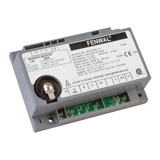
SERIES 35-61 - 60730-2-5 Compliant
24 VAC Microprocessor-Based Direct Spark Ignition
Control with Inducer Blower Relay
FEATURES
•
Safe start with DETECT-A-FLAME
technology
•
Custom pre-purge and inter-purge timings*
•
Inducer blower control and airflow switch monitoring
•
Single or three trials for ignition
•
System diagnostic LED
•
Flame current test points
•
Local or remote flame sensing
•
Automatic reset**
•
True Alarm output or NC (Normally Closed Contact)
available
•
Meets 60730-2-5 Harmonized Standard
APPLICATIONS
•
Gas furnaces
•
Boilers
•
Commercial cooking
•
Water heaters
•
Other gas-fired appliances
DESCRIPTION
The 35-61 is a 24 VAC direct spark ignition (DSI) control
designed for use in all types of gas-fired appliances. The control
uses a microprocessor to continually and safely monitor, analyze
and control the proper operation of a gas burner and inducer
blower. A diagnostic LED and optional UART communications
make troubleshooting easy and ensures safe and efficient
operation.
The optional UART communications offers advanced diagnostic
data and connectivity with the Fenwal ConnectedControl series
05-50 Wi-Fi device.
Export Information (USA)
Jurisdiction: EAR
ECCN: EAR99
Agency Certifications
C22.2 No.0:20
ANSI Z21.20-2014
CAN/CSA C22.2 No. 60730-1:13
RoHS Compliant
®
flame sensing
SPECIFICATIONS
Input Power
Line Voltage
Input Current
Gas Valve
Inducer Blower
Operating Temperature
Storage Temperature
Flame Sensitivity
Flame Failure Response
Gas Types
Spark Rate:
Size (LxWxH)
with enclosure
Moisture Resistance
Ingress Protection
Tries for Ignition
Trial for Ignition Periods
Pre-purge and
Inter-purge Timings
Post-purge Time
Ignition Method
Communications
1
F-35-61H
February 2024
Control: 18-30 VAC 50/60Hz
(Class 2 transformer)
120 or 240 VAC 50/60 Hz
(L1 & IND contacts only)
300 mA @24 VAC with gas valve and
inducer blower relays energized (con-
trol only)
2.0A max @ 24 VAC
3.0 FLA @ 120 VAC (6.0 LRA)
1.5 FLA @ 240 VAC (3.0 LRA)
1/4 H.P. Motor
-40°F to +176°F
(-40°C to +80°C)
-40°F to +185°F
(-40°C to +85°C)
µ
0.7
A minimum
0.8 seconds maximum
Natural, LP, or manufactured
50/60 sparks/sec
5.69 x 3.94 x 1.87 inches
(14.45 x 10.01 x 4.75 cm)
Conformal coated to operate non-
condensing to 95% R.H. Module
should not be exposed to water
Not rated, protection provided by
appliance in which it is installed
One or three try versions available
4, 7, 10, 15 seconds available
0, 15 or 30 seconds available
0, 30 or 60 seconds available
Sparking pulses 600 mS On,
400 mS Off
Optional UART communication
Advertisement

Related Manuals for Fenwal Controls 35-61 Series


Summary of Contents for Fenwal Controls 35-61 Series
- Page 1 SERIES 35-61 - 60730-2-5 Compliant 24 VAC Microprocessor-Based Direct Spark Ignition F-35-61H Control with Inducer Blower Relay February 2024 FEATURES ® • Safe start with DETECT-A-FLAME flame sensing technology • Custom pre-purge and inter-purge timings* • Inducer blower control and airflow switch monitoring •...
- Page 2 SEQUENCE OF OPERATION / FLAME FLAME FAILURE-RECYCLE MODE RECOVERY / SAFETY LOCKOUT With the “Recycle After Loss of Flame" option, upon loss of flame, the gas valve is de-energized and the control proceeds to inter-purge before attempting to relight the flame. Multi-try Power Up / Stand By models permit three tries for ignition including inter-purges.
-
Page 3: Mounting And Wiring
MOUNTING AND WIRING Wiring Diagrams - 35-61 The Series 35-61 control is not position sensitive and can be mounted vertically or horizontally. The case may be mounted on any surface with #6 sheet metal screws. The control also supports direct mounting to a standard NEC 4-in. junction box. Label all wires prior to disconnection when servicing or replacing controls. -
Page 4: Troubleshooting
TROUBLESHOOTING Internal Control Failure If the control detects a software or hardware error, all outputs Troubleshooting Guide are turned off and the LED displays a Steady On condition. If this Symptom Recommended Actions condition persists after an attempt to restart, then the control must be replaced. - Page 5 DIMENSIONS Quick Connect Models Figure 3. Standard Enclosure Note: All dimensions are in inches. F-35-61H Effective: February 2024...
-
Page 6: Part Number Configuration
EX PORT I N FORM ATI ON (USA) Jurisdiction: EAR Classification: EAR99 This document contains technical data subject to the EAR. Fenwal Controls, Kidde-Fenwal Inc. This literature is provided for informational purposes only. 400 Main Street KIDDE-FENWAL, INC. assumes no responsibility for the prod- Ashland, MA 01721 uct’s suitability for a particular application.
Need help?
Do you have a question about the 35-61 Series and is the answer not in the manual?
Questions and answers