
Related Manuals for IBM 7226


Summary of Contents for IBM 7226
- Page 1 7226 Model 1U3 (72261UX) External Storage Device Enclosure 7226 Model 1U3 Storage Device Enclosure Setup, Operator and Service Guide SA23-2271-04...
- Page 3 7226 Model 1U3 (72261UX) External Storage Device Enclosure 7226 Model 1U3 Storage Device Enclosure Setup, Operator and Service Guide SA23-2271-04...
- Page 4 “Notices” on page vii. Fifth Edition (March 2012) This edition, SA23-2271-04, applies to Model 1U3 of the 7226 External Storage Device Enclosure and to all subsequent releases and modifications until otherwise indicated in new editions. This edition applies only to the specified model of the device.
-
Page 5: Table Of Contents
Contents Notices ....vii Installing the 7226 Storage Enclosure Onto the Slide Rails. . 16 Safety and Environmental Notices . viii Installing the Cable Management Arm . - Page 6 Loading and Unloading a DVD Disc . 103 Step 18 (IBM Power System with IBM i Operating Loading a DVD . 103 System Only) . . 131 Unloading a Disc . . 103 7226 Storage Device Enclosure Setup, Operator and Service Guide...
- Page 7 Step 19 (IBM Power System with IBM i Operating Replacing a DVD Drive Feature . . 153 System Only) . . 132 Replacing a USB, SAS or Fibre Channel Interface Step 20 (IBM Power System with IBM i Operating Assembly.
- Page 8 7226 Storage Device Enclosure Setup, Operator and Service Guide...
-
Page 9: Notices
Web sites. The materials at those Web sites are not part of the materials for this IBM product and use of those Web sites is at your own risk. -
Page 10: Safety And Environmental Notices
Questions on the capabilities of non-IBM products should be addressed to the suppliers of those products. All statements regarding IBM's future direction or intent are subject to change or withdrawal without notice, and represent goals and objectives only. This information contains examples of data and reports used in daily business operations. -
Page 11: Attention Notices
An attention notice indicates the possibility of damage to a program, device, system, or data. Electronic Emission Notices The following Statement applies to this IBM product. The statement for other IBM products intended for use with this product will appear in their accompanying manuals. - Page 12 Japanese Statement of Compliance for Products Less than or Equal to 20A per phase 7226 Storage Device Enclosure Setup, Operator and Service Guide...
- Page 13 Klasse A ein. Um dieses sicherzustellen, sind die Geräte wie in den Handbüchem beschrieben su installieren und zu betreiben. Des Weiteren dürfenauch nur von der IBM empfohlene Kabel angeschlossen werden. IBM übernimmt keine Verantwortung für die Einhaltung der Schutzanfordenrungen, wenn das Produkt ohne Empfehlung der IBM gesteckt/eingebaut werden.
- Page 14 Tel: +49 7032 15-2937 e-mail: tjahn@de.ibm.com Generelle Informationen: Das Gerät erfüllt die Schutzanforderungen nach EN 55024 und EN 55022 Klasse Electromagnetic Interference (EMI) Statement - Russia Electromagnetic Interference (EMI) Statement - Korea 7226 Storage Device Enclosure Setup, Operator and Service Guide...
-
Page 15: Electronic Emission Notices For Class B Features
Properly shielded and grounded cables and connectors must be used in order to meet FCC emission limits. Proper cables and connectors are available from IBM-authorized dealers. IBM is not responsible for any radio or television interference caused by unauthorized changes or modifications to this equipment. -
Page 16: Vcci Statement - Japan
This product has been tested and found to comply with the limits for Class B Information Technology Equipment according to European Standard EN 55022. The... -
Page 17: Electromagnetic Interference (Emi) Statement - Korea
Klasse B ein. Um dieses sicherzustellen, sind die Geräte wie in den Handbüchern beschrieben zu installieren und zu betreiben. Des Weiteren dürfen auch nur von der IBM empfohlene Kabel angeschlossen werden. IBM übernimmt keine Verantwortung für die Einhaltung der Schutzanforderungen, wenn das Produkt ohne Zustimmung von IBM verändert bzw. -
Page 18: Product Recycling And Disposal
(TI) que reciclen responsablemente sus equipos cuando éstos ya no les sean útiles. IBM dispone de una serie de programas y servicios de devolución de productos en varios países, a fin de ayudar a los propietarios de equipos a reciclar sus productos de TI. -
Page 19: Battery Return Program
United States, go to http://www.ibm.com/ibm/ environment/products/index.shtml or contact your local waste disposal facility. In the United States, IBM has established a return process for reuse, recycling, or proper disposal of used IBM sealed lead acid, nickel cadmium, nickel metal hydride, and other battery packs from IBM Equipment. - Page 20 Perchlorate Material - special handling may apply. See http://www.dtsc.ca.gov/ hazardouswaste/perchlorate. The foregoing notice is provided in accordance with California Code of Regulations Title 22, Division 4.5 Chapter 33. Best Management Practices for xviii 7226 Storage Device Enclosure Setup, Operator and Service Guide...
-
Page 21: Trademarks
The following terms are trademarks of International Business Machines Corporation in the United States, or other countries, or both: e (Stylized) eServer IBM i IBM Power Systems System i System p System x Other company, product, and service names may be the trademarks or service marks of others. - Page 22 7226 Storage Device Enclosure Setup, Operator and Service Guide...
-
Page 23: About This Guide
About This Guide This guide describes how to install and use the 7226 Model 1U3 Storage Enclosure. It contains the following chapters: Chapter 1, "General Information," describes the 7226 Storage Enclosure, gives the system requirement, discusses cables, and lists hardware specifications. -
Page 24: Related Publications
If you have any comments about this book or any other IBM documentation, fill out the readers' comment form at the back of this book. v If you prefer to send comments by mail, use the readers' comment form with the address that is printed on the back. -
Page 25: Chapter 1. General Information
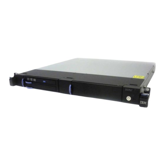
1 EIA Unit (1.75") of a standard 19-inch rack using the rack mount hardware kit. The design of the 7226 storage enclosure allows for easy customer setup, installation and service. The 7226 storage enclosure... - Page 26 Figure 1 shows the 7226 Storage Enclosure with a DAT 160 tape drive installed in Bay A and a DVD assembly with two DVD drives installed in Bay B. ROLSOS503a-0 Figure 1. Front view of the 7226 storage enclosure See the documentation for the system the 7226 is attaching to for information about which features are supported.
-
Page 27: System Requirement
Note: The cooling fans are a part of the enclosure assembly and cannot be replaced separately. Thumbscrew The Thumbscrew is used to attach or remove the top cover of the 7226 Storage Enclosure ( 8 ). System Requirement The following sections describe the host system requirements for the 7226 Model 1U3 Storage Enclosure. - Page 28 Drive features – DAT160 USB Tape drive and HHLTO5 FC Tape drive are not supported v IBMi (OS/400) - Version 6.1.1, or later for the following 7226 drive features: – Supports SAS Tape drives (DAT160 and HHLTO5) and DVD-RAM drive features –...
- Page 29 – Supports all SAS, USB, and FC 7226 Tape (DAT160 and HHLTO5) and RDX drive features v Linux: – SUSE Enterprise Server 10 Service Pack 3, or later – Red Hat Enterprise version 5.5, or later – Supports all SAS, USB, and FC 7226 Tape (DAT160 and HHLTO5) and RDX...
-
Page 30: Ownership Requirements
USB Adapter and Cable: – The DAT160 USB Tape Drive and Removable RDX HDD Docking Station features on 7226 only support the USB cable that is provided as part of the feature code. Additional USB hubs, add-on USB cables, or USB cable extenders are not supported –... -
Page 31: Specifications
Specifications Table 2. Specifications for the 7226 Model 1U3 storage enclosure Physical Specifications Width 438 mm (17.5 in) 480 mm (18.9 in.) Including Right and Left Latch assemblies Depth 454 mm (17.9 in.) Height 43 mm (1.69 in.) Weight 5.1 kg (10.2 lbs) Empty Enclosure 7.1 kg (15.6 lbs) Typical Configuration... -
Page 32: Media Drive Environment And Use
Media Drive Environment and Use IBM's goal is to provide you with a product that you can configure and use reliably. Removable media drives require specific maintenance and environmental conditions to operate well over time. Using high quality, data grade media,... -
Page 33: Environmental Considerations
Place a mark on the cleaning cartridge after each use, to best determine when your cleaning cartridge has expired. IBM only supports the use of IBM cleaning cartridges for IBM tape drives. Chapter 1. General Information... -
Page 34: Sas And Usb Hardware Considerations
SAS and USB Hardware Considerations SAS and USB cables may affect drive performance. IBM cables are designed specifically to keep the bus as free of noise as possible. Use of non-IBM cables may adversely affect performance. If IBM service personnel analysis indicates a problem with non-IBM cables, it may be necessary for the customer to replace them with the appropriate IBM cables. -
Page 35: Chapter 2. Installing The 7226 Storage Enclosure Into A Rack
Chapter 2. Installing the 7226 Storage Enclosure into a Rack The 7226 Storage Enclosure is designed to be installed in one EIA unit (1U) of a standard 19-inch rack using the rack-mount hardware kit. Complete a parts inventory. The following illustration shows the items that you need to install the 7226 Storage Enclosure into the rack cabinet. - Page 36 It is the responsibility of the customer to ensure that the outlet is correctly wired and grounded to prevent an electrical shock. (R001 part 1 of 2) 7226 Storage Device Enclosure Setup, Operator and Service Guide...
- Page 37 (R001 part 2 of 2) Chapter 2. Installing the 7226 Storage Enclosure into a Rack...
-
Page 38: Installing The Slide Rails
Note: The slide rails may be installed in a rack with round or square holes 1. Ensure that the system and the 7226 Storage Enclosure are powered off. 2. Each slide rail is marked with either an R (right) or an L (left) 1 . Select one of the slide rails and push up on the front movable tab 2 ;... - Page 39 Figure 6. Rack front rail and pins 5. Repeat steps 1 through 3 to install the other rail into the rack. Make sure that each front latch is fully seated. Chapter 2. Installing the 7226 Storage Enclosure into a Rack...
-
Page 40: Installing The 7226 Storage Enclosure Onto The Slide Rails
7226 Storage Enclosure and tilt it into position over the slide rails so that the rear posts 2 on the 7226 Storage Enclosure line up with the rear slots 3 on the slide rails. Slide the server down until the rear posts slip into the two rear slots, and then slowly lower the front of the 7226 Storage Enclosure 4 until the other posts slip into the other slots on the slide rails. - Page 41 4. Lift the blue release latches 1 on the slide rails and push the 7226 Storage Enclosure 2 all the way into the rack until it clicks into place. ROLSOS805a-0 Figure 8. Release latches and 7226 Storage Enclosure Note: This step is optional. The screws are only necessary for shipping or in vibration-prone areas.
-
Page 42: Installing The Cable Management Arm
Installing the Cable Management Arm To install the Cable Management Arm, complete the following steps: Note: Do not attach the power cord or other cables to the 7226 Storage Enclosure until you are instructed to do so. The 7226 Storage Enclosure and the computer system that it is attached to will be powered off before the cables are attached. - Page 43 4. To attach the other side of the support arm to the backside of the slide rail, pull the pin out 1 , and then slide the bracket 2 into the slide rail. ROLSOS808-0 Figure 12. Pin extended, bracket installed into slide rail Chapter 2. Installing the 7226 Storage Enclosure into a Rack...
- Page 44 Pull out the other cable-management arm pin 3 , and then slide that cable management arm tab into the slot 4 on the outside of the slide rail. Push the tab until it snaps into place. ROLSOS810-0 Figure 14. Cable-management arm connection 7226 Storage Device Enclosure Setup, Operator and Service Guide...
- Page 45 7. Ensure that the system and the 7226 Storage Enclosure are powered off. 8. Attach the power cords and other cables to the rear of the 7226 Storage Enclosure 1 . Route the cables and power cords on the cable-management arm and secure them with cable ties or hook-and-loop fasteners 2 .
-
Page 46: Removing The 7226 Storage Enclosure From A Rack
Removing the 7226 Storage Enclosure from a Rack To remove the 7226 Storage Enclosure from the rack, complete the following steps: 1. Ensure that the system and the 7226 Storage Enclosure are powered off and the cables have been disconnected from the rear of the device. - Page 47 4. Pull the front locks forward 1 and tilt up the front of the 7226 Storage Enclosure 2 until the front posts slip out of the two front slots. Lift the 7226 Storage Enclosure 3 until the rear posts slip out of the two rear slots and place it in its new location.
-
Page 48: Removing The Cable Management Arm
1. Ensure that the system and the 7226 Storage Enclosure are powered off. 2. Remove the power cords and other cables from the rear of the 7226 Storage Enclosure 1 . Remove the cable ties and fasteners from the cable-management arm 2 and remove the power cords and other cables from the cable-management arm. - Page 49 Figure 20. Slide rail and movable tab 4. Pull out the mounting bracket pin 1 and slide the mounting bracket 2 out of the slide. ROLSOS816-0 Figure 21. Cable Management Arm Chapter 2. Installing the 7226 Storage Enclosure into a Rack...
- Page 50 Figure 22. Support Arm Bracket 6. To remove the cable-management stop bracket, turn the bracket 1 and lift it 2 to release it from the support arm. ROLSOS818-0 Figure 23. Stop Bracket 7226 Storage Device Enclosure Setup, Operator and Service Guide...
- Page 51 7. Swing the support arm 2 away from the rack and remove it from the slide rail. ROLSOS819a-0 Figure 24. Support Arm Chapter 2. Installing the 7226 Storage Enclosure into a Rack...
-
Page 52: Removing The Slide Rails From A Rack
Removing the Slide Rails from a Rack To remove the Slide Rails from a rack, complete the following steps: Note: Remove the 7226 Storage Enclosure and the Cable Management Arm before removing the slide rails. 1. Each slide rail is marked with either an R (right) or an L (left). Select one of the slide rails and push up on the front movable tab 1 ;... - Page 53 2 and push the slide rail in 3 until it releases from the rack. ROLSOS616-0 Figure 27. Rear of the slide rail and pins 5. Repeat steps 1 though 4 for the other slide rail. Chapter 2. Installing the 7226 Storage Enclosure into a Rack...
- Page 54 7226 Storage Device Enclosure Setup, Operator and Service Guide...
-
Page 55: Chapter 3. Attaching The 7226 Storage Enclosure To A Host System
Chapter 3. Attaching the 7226 Storage Enclosure to a Host System This chapter provides step-by-step instructions on how to properly attach and configure the 7226 Model 1U3 Storage Enclosure to a host system. © Copyright IBM Corp. 2012... - Page 56 Electrical voltage and current from power, telephone, and communication cables are hazardous. To avoid a shock hazard: v Connect power to this unit only with the IBM provided power cord. Do not use the IBM provided power cord for any other product.
-
Page 57: Performing The Installation
195) v __ The External Devices Warranty Information (U.S., Canada, and Puerto Rico only) v __ The 7226 Model 1U3 Storage Enclosure Setup, Operator and Service Guide (this guide) v __ The IBM Systems Safety Notices G229-9054 manual v __ SAS, USB or Fibre Channel cables... -
Page 58: Step 2. Checking The Electrical Outlets
Channel cables and ensure that the media can be easily inserted when selecting the location. The 7226 Storage Enclosure should be installed at least 30 inches above the floor to reduce contamination that can affect the drives. To place the 7226 Storage Enclosure, do the following: 1. -
Page 59: Step 5. Connecting The Sas, Usb Or Fibre Channel Cables
1. There is one SAS, USB or Fibre Channel cable connector for each drive installed in the 7226 Storage Enclosure. On the rear of the 7226 Storage Enclosure ( 1 in Figure 28), insert the device connector end of each cable into the cable connector 2 . - Page 60 4. Review the information concerning each drive status LED, then turn on the power to the 7226 Storage Enclosure and watch for the following: v The 7226 Storage Enclosure power-on LED comes on and stays on. v The drive status LEDs blink for up to 60 seconds and go out, indicating that the Power-On Self Test (POST) has completed successfully.
-
Page 61: Step 7. Performing The Checkout Procedure
Step 7. Performing the Checkout Procedure For IBM Power Systems with AIX Operating System To ensure that the devices installed in the 7226 Storage Enclosure have been configured to the host system software perform the following: 1. Log into the host system (AIX operating system level 5.3 or later). - Page 62 If the status is not displayed as Available, refer to Chapter 10, “Troubleshooting,” on page 117. For more information about configuring the 7226 Storage Enclosure to the system software, refer to your AIX or host system manuals. 6. This completes the 7226 Storage Enclosure installation on IBM Power Systems with AIX Operating System.
- Page 63 Drive displays below the adapter, then the host system software has configured it automatically. Note: If the 7226 Tape Drive Feature that you are configuring does not appear below the adapter, check your installation procedure to ensure all settings are correct and the cables are connected correctly and securely. Try the procedure again.
- Page 64 24x/24x writer dvd-ram cd/rw xa/form2 cdda tray __ 4. At the command prompt, type lsscsi and press Enter. The command lists all of devices that are installed in 7226 Storage Enclosure and systems. The output of lsscsi command is: [0:0:0:0]...
-
Page 65: Chapter 4. Removing The 7226 Storage Enclosure From A Host System
Chapter 4. Removing the 7226 Storage Enclosure from a Host System This chapter describes how to remove the 7226 Model 1U3 Storage Enclosure after it has been installed. © Copyright IBM Corp. 2012... - Page 66 Electrical voltage and current from power, telephone, and communication cables are hazardous. To avoid a shock hazard: v Connect power to this unit only with the IBM provided power cord. Do not use the IBM provided power cord for any other product.
-
Page 67: Removal Checklist
6. Disconnect the SAS, USB or Fibre Channel cables from the 7226 Storage Enclosure. 7. To remove the 7226 Storage Enclosure from the rack, see “Removing the 7226 Storage Enclosure from a Rack” on page 22. 8. If reinstalling the 7226 Storage Enclosure, see Chapter 3, “Attaching the 7226 Storage Enclosure to a Host System,”... - Page 68 7226 Storage Device Enclosure Setup, Operator and Service Guide...
-
Page 69: Chapter 5. The Dat 160 Tape Drive Features
Chapter 5. The DAT 160 Tape Drive Features This chapter describes the 7226 Model 1U3 Storage Device Enclosure Feature #5619 and #EU16, the DAT 160, Tape Drives. It describes operator controls and indicator LEDs, outlines instructions for loading and ejecting a tape cartridge, and tells how to clean the tape drive. -
Page 70: Feature Kit Contents
Feature Kit Contents The 7226 Model 1U3 Storage Enclosure drive feature codes #5619 and #EU16 provide a DAT 160 tape drive kit with the following content: Table 3. Feature Code 5619 and EU16 Contents Description FC 5619 FC EU16 Quantity... -
Page 71: Operation Features
AIX to log an information error (TAPE_ERR6) in the AIX log, indicating that the tape drive needs to be cleaned. 4. Use only IBM media. IBM only supports the use of IBM media and IBM cleaning cartridges. 5. The tape drive is designed to operate in normal office environments. Dirty environments or other poor environments may damage the tape drive. - Page 72 7. If a tape cartridge that is not DDS-4, DAT 72 or DAT 160 format is used, that cartridge will be immediately ejected as an incorrect cartridge type. 7226 Storage Device Enclosure Setup, Operator and Service Guide...
- Page 73 Table 4. Definition of Status Light Combinations Activity Cleaning Media Fault Drive Fault Ready /Activity (amber) (amber) (green) (amber) Power on LED test (2.0 seconds) Power on Flashing self-test (POST) activity POST failed Flashing POST passed or off Data cartridge or off Flashing loading...
- Page 74 An unrecoverable media failure is usually the result of a defective cartridge, media, or cartridge state, and will require the drive to eject the cartridge (if possible) to clear the On LED. 7226 Storage Device Enclosure Setup, Operator and Service Guide...
-
Page 75: Dat 160 Drive Connectors
Loading a Tape Cartridge To load a tape cartridge: 1. Make sure that the 7226 Storage Enclosure power is on (the power-on symbol should be illuminated). 2. Grasp the cartridge by the outer edges, with the window side up and the write-protect switch facing you. -
Page 76: Unloading A Tape Cartridge
To indicate that the load operation was successful, the Ready status LED comes on. Unloading a Tape Cartridge To unload a tape cartridge: 1. Make sure that the 7226 Storage Enclosure power is on (the power-on symbol should be illuminated). 2. Press the eject button. -
Page 77: Cleaning The Tape Drive
To clean the DAT 160 Tape Drive tape drive: 1. Make sure that the power is on to the 7226 Storage Enclosure. 2. If a tape cartridge is in the DAT 160 tape drive, eject and remove the cartridge. -
Page 78: Dat 160 Tape Drive Self-Test Procedure
With a fully written cartridge the self-test will still be able to write the small amount of data it needs to write, but can take up to 10 minutes to complete the test. 7226 Storage Device Enclosure Setup, Operator and Service Guide... - Page 79 a. A cartridge must be loaded within 15 seconds -- otherwise, the drive will automatically revert back to normal operation. If necessary, return to step 1 to re-enter diagnostic mode. b. Use a cartridge that is not write-protected. If a write-protected tape is loaded, the tape will load normally and allow data to be read from it.
-
Page 80: Types Of Tape Cartridges
(for information about running diagnostics, refer to your AIX manuals). The test cartridge should not be used to save or restore customer programs or data. Cleaning Cartridge Use the specially labeled cleaning cartridge (part number 21F5638) 7226 Storage Device Enclosure Setup, Operator and Service Guide... - Page 81 DAT 160 Drive. For instructions about how to clean the DAT 160 Drive, see “Cleaning the Tape Drive” on page 53). Attention: Use of other than the IBM DAT 160 cleaning cartridge can damage your DAT 160 Drive and may void your warranty.
-
Page 82: Recommendations For Data Cartridge Usage
Attach a barcode label to each tape cartridge. Use only barcode labels that were supplied by IBM. Labels marked CLNxxx should only be used for cleaning cartridges. v Use only one label on a tape cartridge. Multiple or poorly placed labels can clog the drive load mechanism. -
Page 83: Prolonging Head Life
Prolonging Head Life New technology found in the tape device is read and write compatible with newer tape cartridges. Due to media characteristics, extended use of older tape cartridges might increase head wear on the drive. An indication of this head wear is an increase in soft (recoverable) errors. -
Page 84: Tape Cartridge Storage
Data Cartridge Erasure Do not attempt to bulk erase an DAT 160 data cartridge for reuse. Most bulk eraser devices do not have the capability to erase the data cartridge. 7226 Storage Device Enclosure Setup, Operator and Service Guide... -
Page 85: Setting The Write-Protect Switch
IBM only supports using data and cleaning cartridges supplied by IBM. Use only data grade tape media for backup and data processing. Saving money by using generic media for data purposes will do little to save your business if your data is destroyed and your backup tapes fail because of inferior media. - Page 86 7226 Storage Device Enclosure Setup, Operator and Service Guide...
-
Page 87: Chapter 6. The Half High Lto-5 Tape Drive Feature
Chapter 6. The Half High LTO-5 Tape Drive Feature This chapter describes the 7226 Model 1U3 Storage Device Enclosure Features #8247 and #8248, the Half High LTO-5 Tape Drives. It describes operator controls and indicator LEDs, gives instructions for loading and unloading a tape cartridge, and tells how to clean the tape drive. -
Page 88: Feature Kit Contents
Feature Kit Contents The 7226 Storage Enclosure drive feature codes #8247 or #8248 provide an LTO-5 tape drive kit with the following content: Table 7. Feature Codes 8247 and 8248 Contents Description FC #8247 FC #8248 Quantity Quantity LTO 5 SAS Tape Drive... -
Page 89: Operation Features
Operation Features The half high LTO tape drive has the following operator controls. Unload Button The unload button ( 1 in Figure 35 on page 66) is used to eject an installed tape cartridge, perform maintenance functions, and reset the drive. The unload button operates only when the power is on. -
Page 90: Indicator Leds
2. When a fault occurs, the drive causes AIX to log an information error (TAPE_ERR6) in the AIX log, indicating that the tape drive needs to be cleaned. 3. Use only IBM media. IBM only supports the use of IBM media and IBM cleaning cartridges. -
Page 91: Rear View Of The Lto Tape Drive
Figure 36 shows the connector locations on the drive. Note: This view is of the connections on rear of the drive assembly, located inside the 7226 Device Enclosure. Note: Use only the lower Fibre Channel connector on the LTO5 Fibre Channel Tape Drive as shown. -
Page 92: Single-Character Display (Scd)
Table 8. Status LED Combinations Mode Ready LED (green) Fault LED (amber) Operational Blank Activity (tape Blank Flashing movement) in Operational Mode Maintenance Solid character Executing Flashing character Maintenance Selection Error Condition Solid character Flashing 7226 Storage Device Enclosure Setup, Operator and Service Guide... - Page 93 Table 8. Status LED Combinations (continued) Mode Ready LED (green) Fault LED (amber) Power-On / Reset random segments Initialization Table 9 lists the conditions of the Status LEDs and Single-character Display (SCD) and provides an explanation of what each condition means. Table 9.
- Page 94 It will reset per second) automatically. Amber/Solid Flashing C The drive is requesting a cartridge to be loaded. Flashing There is a drive dump in flash memory. Amber (twice per second) 7226 Storage Device Enclosure Setup, Operator and Service Guide...
-
Page 95: Unload Button
Unload Button The Unload Button ( 1 in Figure 35 on page 66) performs the following functions: Table 10. Unload Button Functions Unload Button Function How to Initiate the Function Rewind the tape into Press the Unload Button once. The Status LED flashes green while the cartridge and eject the drive is rewinding and unloading. -
Page 96: Diagnostic And Maintenance Functions
81. To clear the error, turn the power off, then on again. Note: The drive also exits maintenance mode automatically after it completes a maintenance function or after 10 minutes if no action has occurred. 7226 Storage Device Enclosure Setup, Operator and Service Guide... -
Page 97: Function Code 0: Maintenance Mode
Function Code 0: Maintenance Mode Function Code 0 makes the drive available for running drive diagnostics or maintenance functions (see “Entering Maintenance Mode” on page 72 and “Exiting Maintenance Mode” on page 72). The drive exits Maintenance Mode automatically after it completes a maintenance function or after 10 minutes if no action has occurred. -
Page 98: Function Code 4: Force A Drive Dump
4. If you selected 5 - 0 the drive will exit Maintenance Mode. If you selected 5 - 8 or 5 - 3 the SCD will change to a flashing 5 while the procedure is being 7226 Storage Device Enclosure Setup, Operator and Service Guide... -
Page 99: Function Code 9: Display Error Code Log
performed. After the procedure is completed the drive will exit Maintenance Mode. If you selected 5 - 1 the SCD will change to a flashing C indicating that a data cartridge is to be inserted. 5. Insert a scratch (blank) data cartridge within 60 seconds, or the drive will exit Maintenance Mode. -
Page 100: Function Code E: Test Cartridge & Media
During the test, the drive overwrites the data on the cartridge. Note: If you inserted an invalid tape cartridge (Gen1 or WORM media, for example), error code 7 appears in the SCD. If you inserted a write-protected 7226 Storage Device Enclosure Setup, Operator and Service Guide... -
Page 101: Function Code H: Test Head
cartridge, or the media has read-only compatibility (Gen2 media, for example), error code P appears in the SCD. In either case, the tape drive unloads the cartridge and exits Maintenance Mode after the cartridge is removed. 1. Place the drive in Maintenance Mode. For instructions, see “Entering Maintenance Mode”... -
Page 102: Function Code J: Fast Read/Write Test
2. Press the Unload Button once per second until J appears in the SCD. (If you cycle past the desired code, press the Unload Button once per second until the code reappears.) 7226 Storage Device Enclosure Setup, Operator and Service Guide... -
Page 103: Function Code L: Load/Unload Test
3. Press and hold the Unload Button for three or more seconds, then release it to select the function. The SCD changes to a flashing C . 4. Insert a scratch (blank) data cartridge. The SCD changes to a flashing J and the tape drive runs the tests. -
Page 104: Function Code U: Post Error Reporting Disabled
P appears in the SCD. The SCD changes to U after you release the Unload Button. 5. Press the Unload Button once per second to select another Maintenance Mode Function. To exit Maintenance Mode, refer to “Exiting Maintenance Mode” on page 72. 7226 Storage Device Enclosure Setup, Operator and Service Guide... -
Page 105: Error Codes And Messages
Error Codes and Messages If the drive detects a permanent error, it will display the error code on the SCD and flash the Amber Fault LED (Green Ready LED will be Off). v Make note of the SCD error code prior to removing a cartridge or clearing the SCD error code. - Page 106 If the problem persists, download new firmware and retry the operation. v If the problem persists, send the drive dump that you collected to your IBM Support Center. The error code clears when you place the tape drive in maintenance mode.
- Page 107 Table 11. LTO-5 Tape Drive Error Codes (continued) Error Code Cause and Action Tape drive or media error. The tape drive determined that an error occurred, but it cannot isolate the error to faulty hardware or to the tape cartridge. Ensure the tape cartridge is the correct media type: v Ultrium -1 tape cartridges are not supported in Ultrium-5 tape drives.
- Page 108 RS-422 connection. Refer to the Library procedures to isolate the problem to the drive. The error code clears when you place the tape drive in maintenance mode. 7226 Storage Device Enclosure Setup, Operator and Service Guide...
- Page 109 Table 11. LTO-5 Tape Drive Error Codes (continued) Error Code Cause and Action Degraded operation. The tape drive determined that a problem occurred which degraded the operation of the tape drive, but it did not restrict continued use. If the problem persists, determine whether the problem is with the drive or the media.
-
Page 110: Troubleshooting
The error code clears when you remove the tape cartridge or place the tape drive in maintenance mode. Troubleshooting This section describes problems you might encounter while operating the IBM half-high LTO-5 tape drive, and provides suggestions for resolving those common problems... -
Page 111: Tape Drive Will Not Eject A Tape Cartridge
2. a) Confirm that the drive is operating with latest-level firmware. Download new firmware from the IBM web site, if needed. 3. If you are unable to eject the cartridge, contact your authorized IBM service representative. Fault LED is Flashing A flashing Fault LED ( ) indicates that a tape drive error has been detected. -
Page 112: The Host System Backup Application Is Reporting An Error
4. If you are trying to backup (write) data, verify that your cartridge is not write-protected. Check the red write-protect switch on the edge of the cartridge, and confirm that it is in the unlocked position (see “Setting the Write-Protect Switch” on page 95). 7226 Storage Device Enclosure Setup, Operator and Service Guide... -
Page 113: Using Lto Ultrium Media
Using LTO Ultrium Media Use only IBM LTO Ultrium tape cartridges in the LTO tape drive. You may use other LTO-certified data cartridges, but they may not meet the standards of reliability that are established by IBM. The IBM LTO Ultrium Data Cartridges cannot be interchanged with the media used in other IBM non-LTO Ultrium tape products. -
Page 114: Cartridge Memory Chip (Lto-Cm)
Cartridge Memory Chip (LTO-CM) All generations of the IBM LTO Ultrium Data Cartridges include a Linear Tape-Open Cartridge Memory (LTO-CM) chip ( 1 in Figure 37 on page 89), that contains information about the cartridge and the tape (such as the name of the manufacturer that created the tape), as well as statistical information about the cartridge use. -
Page 115: Cleaning The Tape Drive
2. If a tape cartridge is in the LTO tape drive, eject and remove the cartridge. Note: The IBM cleaning cartridge is designed to be used for 50 cleanings. Once a cleaning cartridge has been used to its maximum number of uses, the cartridge is considered expired. - Page 116 Attention: Use of other than the IBM LTO cleaning cartridge can damage your LTO tape drive and may void your warranty. IBM also offers other LTO cartridges for smaller capacity storage and testing. Use the specially labeled LTO test cartridge to run the system diagnostics (for information about running diagnostics, refer to your host system manuals).
-
Page 117: Recommendations For Data Cartridge Usage
The following list describes recommended guidelines that will help to protect your data and prolong the life of your tape cartridges and the LTO tape drive: v Use only IBM media cartridges. v Remove the tape cartridge from the drive when the drive is not in use. -
Page 118: Tape Cartridge Storage
Sunlight can damage the tape and the cartridge shell. Store tape cartridges out of the direct sunlight Attention: Operation outside of the recommended environment can result in possible loss of data or failure of the drive. 7226 Storage Device Enclosure Setup, Operator and Service Guide... -
Page 119: Operating In Harsh Environments
Operating in Harsh Environments Do not use as an archival tape any tape that has been used outside of the operating ranges specified in Table 2 on page 7 for an extended period of time. The magnetic and physical strength of the tape will have deteriorated as a result of its exposure to the environment. -
Page 120: Guidelines For Using Labels On Ultrium Cartridges
Guidelines for Using Labels on Ultrium Cartridges Apply the following guidelines whenever using labels: v Use only IBM-approved labels on cartridges to be used in an IBM tape drive or library. v Do not reuse a label or reapply a used label over an existing label. -
Page 121: Ordering Tape Cartridges
IBM supports using only data and cleaning cartridges supplied by IBM. Data grade tape media is the only type of tape media that should be used for backup and data processing. Saving money by using generic media for data purposes will do little to save your business if your data is destroyed and your backup tapes fail because of inferior media. - Page 122 7226 Storage Device Enclosure Setup, Operator and Service Guide...
-
Page 123: Chapter 7. The Dvd Drive Features
#1420 and #1422, the SAS DVD-RAM Drives; and #5757 and #5762, the USB DVD-RAM Drives. It describes operator controls and indicator LEDs, gives instructions for loading and unloading a DVD disc. The 7226 Storage Device Enclosure is capable of utilizing up to four slim DVD drives. The DVD drives 1 are installed in a Slim Tray 2 that is installed in either bay of the storage enclosure. -
Page 124: Feature Kit Contents
– Multi-session CD-ROM discs to the Orange Book Standard Feature Kit Contents The 7226 Model 1U3 Storage Enclosure drive feature codes 1420 and 5762 provide a DVD drive kit that includes a Slim Drive Tray for installation in an empty drive bay. - Page 125 Table 14. Feature Code 1420, 5762, 1422 and 5757 Contents (continued) Description FC 1420 FC 5762 FC 1422 FC 5757 Quantity Quantity Quantity Quantity DVD RAM Test disc ROLG035-0 5.5M SAS Cable ROLG004a-0 3M USB Cable ROLG014-0 Chapter 7. DVD-RAM Drive...
-
Page 126: Operator Controls
The load/unload button operates only when the 7226 Storage Enclosure power is on. The load/unload button does not operate while the device is in use. -
Page 127: Loading And Unloading A Dvd Disc
SATA/SAS Re-driver Card SAS Power/Signal connector ROLG040a-0 SATA/USB Power connector Converter Card USB Connector Figure 42. Rear View of the DVD Drive Assembly Loading and Unloading a DVD Disc Loading a DVD Use the following instructions to load or unload a DVD disc. Notes: 1. -
Page 128: Recommendations For Disc Usage
IBM only supports using DVD discs supplied by IBM. Data grade media is the only type of media that should be used for backup and data processing. Saving money by using generic media for data purposes will do little to save your business if your data is destroyed and your backup discs fail because of inferior media. -
Page 129: Storage And Shipping Environments
Storage and Shipping Environments Before using a disc, let it acclimate to the operating environment by placing the disc in the environment for as long as it has been away from the environment or for 24 hours, whichever is less. Retrieval of archived data should be performed on a unit that is clean and fully operational. - Page 130 7226 Storage Device Enclosure Setup, Operator and Service Guide...
-
Page 131: Chapter 8. The Rdx Removable Disk Drive Features
Emergency eject hole Cartridge indicator LED Eject button and power indicator LED ROLSOS600-0 Figure 43. Front view of the RDX Drive Docking Station © Copyright IBM Corp. 2012... - Page 132 Write-protect switch ROLSOS601-0 Figure 44. Front view of the RXD Drive Assembly Power connector USB connector ROLSOS602-0 Figure 45. Rear view of the RDX Drive Docking Station 7226 Storage Device Enclosure Setup, Operator and Service Guide...
-
Page 133: Feature Kit Contents
Purchasing additional RDX Data Cartridges For best results, use only the removable disk drives that are shown in Table 18 Table 18. RDX Data Cartridges Feature Code IBM Part Number Type of Cartridge 1106 46C5375 160 GB RDX Data Cartridges... -
Page 134: Storing Removable Disk Drives
Data Cartridges in other locations, contact your local provider of IBM storage products or visit the following Web site: http://www.storage.ibm.com/media/. RDX Data Cartridges are not a service item and IBM service representatives are not dispatched to service or replace removable disk drives. -
Page 135: Supported Operating Systems
Supported operating systems USB Removable Disk Drive is supported on the following versions of the AIX and ® Linux operating systems: v AIX 5L Version 5.3 with the 5300-11 Technology Level, or later v AIX Version 6.1 with the 6100-04 Technology Level, or later v Red Hat Enterprise Linux version 3 Update 7, or later v SUSE Linux Enterprise Server 10, or later Using the USB Removable Disk Drive for backup and restore... -
Page 136: Using The Emergency Eject Function
Restart your system to reset the docking station. If you are using the external docking station, reconnect the power cable for the docking station and then restart the system. 7226 Storage Device Enclosure Setup, Operator and Service Guide... -
Page 137: Status Leds
Status LEDs Learn about the power indicator and drive indicator status LEDs on the USB Removable Disk Drive. Power indicator The eject button is illuminated by a power indicator LED. The following table describes the operation of the power indicator. Table 20. - Page 138 7226 Storage Device Enclosure Setup, Operator and Service Guide...
-
Page 139: Chapter 9. The Quad External Sas Cable Feature
SAS cable that is provided with each tape drive or DVD-RAM feature ordered. Up to four 7226 SAS devices may be attached to a single SAS port using a one-to-four Quad External SAS Cable (feature #5544). The four 7226 SAS devices may be installed in more than one 7226 storage enclosure. - Page 140 7226 Storage Device Enclosure Setup, Operator and Service Guide...
-
Page 141: Chapter 10. Troubleshooting
It is the responsibility of the customer to ensure that the outlet is correctly wired and grounded to prevent an electrical shock. (R001 part 1 of 2) © Copyright IBM Corp. 2012... -
Page 142: Purpose Of The Flowcharts
Power cord Drives The 7226 Storage Enclosure and Drive Features include several LED's that indicate the presence and source of a fault. The drives have the capability to report faults to the operating system. These should be the primary sources for fault identification. -
Page 143: Flowchart For Ibm Power Systems With Aix Operating System
Proceed to Step 6 Step 16 Fail Run AIX Replace failing diagnostics drive and Replace FRU/contact return to Step 1 service personnel Pass Problem fixed ROLSOS505-0 Figure 47. Flowchart for IBM Power Systems with AIX Operating System Chapter 10. Troubleshooting... -
Page 144: Flowchart For Ibm Power Systems With Ibm I Operating System
Did the Verify Clean the drives on failure test pass? and retry Fail Problem Fixed Problem Fixed ROLSOS529-0 Figure 48. Flowchart for IBM Power Systems with IBM i Operating System 7226 Storage Device Enclosure Setup, Operator and Service Guide... -
Page 145: Flowchart For Ibm Power Systems With Linux Operating System
Is an AIX stand alone replacement FRU or diagnostics CD service action? available? Replace FRU/contact Go to Step 16 service personnel on page 145 Contact service personnel ROLSOS901-0 Figure 49. Flowchart for IBM Power Systems with Linux Operating System Chapter 10. Troubleshooting... -
Page 146: Flowchart For Ibm System X
Drives power Replace drive up normal? and return to Step 1 Proceed to Step 6 Replace failing drive and return to Step 1 ROLSOS505-0 Figure 50. Flowchart for IBM System x 7226 Storage Device Enclosure Setup, Operator and Service Guide... -
Page 147: Step 1
3. Press the power switch on the 7226 storage enclosure. 4. Check the state of the power-on LED on the front of the 7226 storage enclosure. Note: The power-on LED is located on the power switch. -
Page 148: Step 4
This step checks the power supply voltage levels as the possible source of the problem. 1. Press the power switch to turn off the power to the 7226 Storage Enclosure. 2. Unplug the 7226 Storage Enclosure from the electrical outlet. -
Page 149: Step 6
Step 6 This step examines the enclosure cooling fan as the possible source of the problem. 1. Press the power switch to turn on the power to the 7226 Storage Enclosure. 2. Is the Fan Fault LED on? Replace the Enclosure. -
Page 150: Step 9
This step checks the enclosure power as the possible source of the problem. 1. Press the power switch to turn off the power to the 7226 Storage Enclosure. 2. Disconnect the power cables from the Tape Drives, SAS Interface Assemblies, and RDX Docking Stations. -
Page 151: Step 10
Step 10 This step examines the drives as the possible source of the problem. 1. Press the power switch to turn off the power to the 7226 Storage Enclosure. 2. Disconnect the power connector from the drive in Bay A. -
Page 152: Step 13
This step determines whether an internal SAS, USB or Fibre Channel Interface Assembly is the source of the problem. 1. Press the power switch to turn off the power to the 7226 Storage Enclosure. 2. Disconnect the internal SAS, USB or Fibre Channel Interface Assemblies from the media devices. -
Page 153: Step 15 (Ibm Power System With Aix Operating System Only)
Step 15 (IBM Power System with AIX Operating System Only) This step verifies that the 7226 storage enclosure has been properly configured to the IBM Power System with AIX Operating System. Check the configuration of the 7226 storage enclosure to the host system software by doing the following: 1. -
Page 154: Step 16 (Ibm Power System With Aix Operating System Only)
If the status is not displayed as Available, refer to Chapter 10, “Troubleshooting,” on page 117. For more information about configuring the 7226 Storage Enclosure to the system software, refer to your AIX or host system manuals. Is the 7226 storage enclosure properly configured to the host system? Go to Step 16 (IBM Power System with AIX Operating System Only). -
Page 155: Step 17 (Ibm Power System With Ibm I Operating System Only)
This completes the MAPs for the IBM Power System with AIX Operating System. Step 17 (IBM Power System with IBM i Operating System Only) You are here because the host system is an IBM Power System with IBM i Operating System or iSeries host system. This step verifies that the installed devices are properly configured to the host system. -
Page 156: Step 19 (Ibm Power System With Ibm I Operating System Only)
Enter. The Logical Hardware Resources Associated with IOP screen displays with a list of devices that are configured to the SAS controller. The 7226 Tape Drive and its tape controller appear in the list and display a status of Operational. -
Page 157: Step 21 (Ibm Power System With Linux Operating System Only)
If a FRU was replaced or changed and no more errors occur, the problem is fixed. This completes the MAPs for the IBM Power System with IBM i Operating System. Step 21 (IBM Power System with Linux Operating System Only) -
Page 158: Step 24 (Ibm Power System With Linux Operating System Only)
Replace FRU or contact service personnel. Go to Step 24. This completes the MAPs for the IBM Power System with Linux Operating System. Step 24 (IBM Power System with Linux Operating System Only) Is an AIX stand alone diagnostic CD available? Go to Step 16 (IBM Power System with AIX Operating System Only) Contact service personnel. -
Page 159: Chapter 11. Installation And Removal Procedures
Chapter 11. Installation and Removal Procedures This chapter provides step-by-step instructions on how to physically install and remove the storage device features and other components in the 7226 Model 1U3 Storage Enclosure. © Copyright IBM Corp. 2012... - Page 160 Electrical voltage and current from power, telephone, and communication cables are hazardous. To avoid a shock hazard: v Connect power to this unit only with the IBM provided power cord. Do not use the IBM provided power cord for any other product.
-
Page 161: Laser Safety Information
Attention: The 7226 Storage Enclosure is a precision device that requires reasonable care in handling to prevent data loss or permanent damage to the device. Avoid bumping or dropping the 7226 Storage Enclosure or device features. Ensure all media is removed from the device before the drive is moved. -
Page 162: Preparing The 7226 Storage Enclosure For Removal Or Installation Of A Storage Device Or Other Component
4. Unplug the 7226 Storage Enclosure power cable from the electrical outlet. The 7226 Storage Enclosure is now prepared for removal or installation of a storage device or other component. Refer to the appropriate procedure in this chapter. -
Page 163: Installing A Tape Drive Feature Or A Removable Disk Drive Feature
FC 8247 or 8248, see “Feature Kit Contents” on page 64. For the contents of FC 1103, see “Feature Kit Contents” on page 109. 1. Prepare the 7226 Storage Enclosure for Service. See “Preparing the 7226 Storage Enclosure for Removal or Installation of a Storage Device or Other Component”... - Page 164 5. Attach the Interface Assembly to the drive connector 1 , and attach the Power Connector 2 . For Fibre Channel Cables, also attach the power jumper 3 . Fibre Channel ROLG060f-0 Figure 56. Attach Interface Assembly and Power Cable 7226 Storage Device Enclosure Setup, Operator and Service Guide...
- Page 165 3 until it clicks into place. ROLSOS856-0 Figure 58. Insert Interface Assembly Back Plate 8. Complete the 7226 Storage Enclosure Service Procedure. See “Completing the 7226 Storage Enclosure Service Procedure” on page 177 for the correct procedure. Chapter 11. Installation and Removal Procedures...
-
Page 166: Installing A Dvd Drive Feature 1420 Or 5762
Storage Enclosure for Removal or Installation of a Storage Device or Other Component” on page 138 for the correct procedure. 2. Open the 7226 Storage Enclosure for Service. See “Opening the 7226 Storage Enclosure for Service” on page 174 for the correct procedure. - Page 167 6. Attach the Drive Latch 1 to the Slim Tray 2 and insert both into the drive bay until they click into place. ROLSOS866-0 Figure 60. Insert DVD Tray Assembly 7. To remove the Blank Back Plate, pull the back plate pin 1 to release the Blank Back Plate, and remove the Blank Back Plate 2 from the rear panel slot.
- Page 168 Attach the power connector 2 . Ensure that the Interface Assembly and cables are routed under the cross bar 3 . ROLG070b-0 Figure 63. Connect Interface Assembly and power connector 7226 Storage Device Enclosure Setup, Operator and Service Guide...
- Page 169 10. Complete the 7226 Storage Enclosure Service Procedure. See “Completing the 7226 Storage Enclosure Service Procedure” on page 177 for the correct procedure. Chapter 11. Installation and Removal Procedures...
-
Page 170: Installing A Dvd Drive Feature 1422 Or 5757
Storage Enclosure for Removal or Installation of a Storage Device or Other Component” on page 138 for the correct procedure. 2. Open the 7226 Storage Enclosure for Service. See “Opening the 7226 Storage Enclosure for Service” on page 174 for the correct procedure. - Page 171 5. To install the new SATA/SAS Re-driver card or SATA/USB Converter card, align the card slides with the slots on the rear of the slim drive tray. Slide the card into position in the rear of the Slim tray 1 . Tighten the thumbscrews ROLSOS868-0 Figure 65.
- Page 172 1 , pull the pin on the back plate 2 and push the back plate into the back panel opening 3 until it clicks into place. ROLSOS873-0 Figure 68. Insert Interface Assembly Back Plate 7226 Storage Device Enclosure Setup, Operator and Service Guide...
- Page 173 9. Attach the Interface Assembly 1 to the re-driver card connector or converter card connector. Attach the power connector 2 . Ensure that the SAS Interface Assembly is routed under the cross bar 3 . ROLG070b-0 Figure 69. Connect Interface Assembly and power connector Chapter 11.
- Page 174 ROLSOS870a-0 Figure 71. Inserting a DVD 12. Complete the 7226 Storage Enclosure Service Procedure. See “Completing the 7226 Storage Enclosure Service Procedure” on page 177 for the correct procedure. 7226 Storage Device Enclosure Setup, Operator and Service Guide...
-
Page 175: Replacing A Tape Drive Feature Or A Removable Disk Drive Feature
Enclosure for Removal or Installation of a Storage Device or Other Component” on page 138 for the correct procedure. Note: The 7226 Storage Enclosure does not need to be extended from the rack for this procedure. 2. Determine the location for the Drive Feature to be replaced. - Page 176 Figure 73. Inserting a Drive 7. Attach the power cord and other cables to the rear of the enclosure. 8. Power on the 7226 storage enclosure. 9. Refer to your system manuals to verify installation. 7226 Storage Device Enclosure Setup, Operator and Service Guide...
-
Page 177: Replacing A Dvd Drive Feature
Enclosure for Removal or Installation of a Storage Device or Other Component” on page 138 for the correct procedure. Note: The 7226 Storage Enclosure does not need to be extended from the rack for this procedure. 2. Determine which DVD Drive will be replaced. - Page 178 5. Attach the Slim Drive Latch 1 to the DVD Drive 2 and insert both into the slim drive bay until they click into place. ROLSOS834b-0 Figure 75. Inserting a DVD 6. Power on the 7226 storage enclosure. 7. Refer to your system manuals to verify installation. 7226 Storage Device Enclosure Setup, Operator and Service Guide...
-
Page 179: Replacing A Usb, Sas Or Fibre Channel Interface Assembly
Replacing a USB, SAS or Fibre Channel Interface Assembly 1. Prepare the 7226 Storage Enclosure for Service. See “Preparing the 7226 Storage Enclosure for Removal or Installation of a Storage Device or Other Component” on page 138 for the correct procedure. - Page 180 Note: The internal power connector does not need to be removed from a USB drive or a Fibre Channel drive. Fibre Channel ROLG061b-0 Figure 77. Remove Interface Assembly and Power Cable 6. Locate the new interface assembly 7226 Storage Device Enclosure Setup, Operator and Service Guide...
- Page 181 7. Attach the Interface Assembly 1 to the drive connector, and attach the Power Connector 2 . Note: The power connector is only attached to the SAS Interface Assembly. Fibre Channel ROLG062b-0 Figure 78. Attach Interface Assembly Chapter 11. Installation and Removal Procedures...
- Page 182 ROLSOS856-0 Figure 79. Insert Interface Assembly Back Plate 9. Complete the 7226 Storage Enclosure Service Procedure. See “Completing the 7226 Storage Enclosure Service Procedure” on page 177 for the correct procedure. 7226 Storage Device Enclosure Setup, Operator and Service Guide...
-
Page 183: Replacing A Sata/Sas Re-Driver Card Or Sata/Usb Converter Card
Storage Enclosure for Removal or Installation of a Storage Device or Other Component” on page 138 for the correct procedure. Note: The 7226 Storage Enclosure does not need to be extended from the rack for this procedure. 2. Determine the location of the SATA/SAS re-driver card or SATA/USB converter card to be replaced. - Page 184 5. Place the Slim Drive Tray assembly on an ESD protected work surface. 6. Locate the re-driver and converter cards on the rear of the Slim Drive Tray Assembly. There may be one or two cards. Locate the card to be replaced. 7226 Storage Device Enclosure Setup, Operator and Service Guide...
- Page 185 7. To remove the card, loosen the thumbscrews 1 . Slide the card out of the rear of the Slim tray 2 . ROLSOS841-0 Figure 82. Remove the re-driver or converter card 8. To install the new re-driver or converter card, align the card slides with the slots on the rear of the slim drive tray.
- Page 186 Figure 85. Install DVD Drive 11. Attach the power cord and other cables to the rear of the enclosure. 12. Power on the 7226 storage enclosure. 13. Refer to your system manuals to verify installation. 7226 Storage Device Enclosure Setup, Operator and Service Guide...
-
Page 187: Replacing A Slim Drive Tray
Storage Enclosure for Removal or Installation of a Storage Device or Other Component” on page 138 for the correct procedure. Note: The 7226 Storage Enclosure does not need to be extended from the rack for this procedure. 2. Determine the location for the Slim Drive Tray to be replaced. - Page 188 6. Locate the re-driver cards and converter cards on the rear of the Slim Drive Tray Assembly. There may be one or two cards. Ensure that both are moved to the new Slim Drive Tray. 7226 Storage Device Enclosure Setup, Operator and Service Guide...
- Page 189 7. To remove the SATA/SAS re-driver card or SATA/USB converter card, loosen the thumbscrews 1 . Slide the card out of the rear of the Slim tray 2 . ROLSOS841-0 Figure 88. Remove the SATA/SAS re-driver card or SATA/USB converter card. 8.
- Page 190 Figure 91. Install DVD Drive 12. Attach the power cord and other cables to the rear of the enclosure. 13. Power on the 7226 storage enclosure. 14. Refer to your system manuals to verify installation. 7226 Storage Device Enclosure Setup, Operator and Service Guide...
-
Page 191: Replacing An Enclosure
Storage Enclosure for Removal or Installation of a Storage Device or Other Component” on page 138 for the correct procedure. 2. Remove the 7226 Storage Enclosure from the rack (See “Removing the 7226 Storage Enclosure from a Rack” on page 22) and place it on an ESD protected work surface. - Page 192 4. Note the location of the devices in the old 7226. Remove the Half High Bay Blanks from those locations in the Enclosure FRU. To remove the Half High Bay Blank, push the drive latch 1 toward the Half High Bay Blank and begin to pull the blank out of the enclosure.
- Page 193 6. Install each device into Enclosure FRU into the its noted location. To install the drive assemblies, attach the Drive Latch 1 to the drive assembly 2 and insert both into the drive bay until they click into place. ROLSOS862b-0 Figure 95.
- Page 194 9. Note the location of each Interface Assembly in the 7226. To remove each Interface assembly from the 7226, remove the Interface Assembly from the drive connector 1 and remove the power connector 2 . Fibre Channel ROLG063b-0 Figure 98. Remove Interface Assembly and Power Cable...
- Page 195 10. Note the locations of the Blank Back Plates to be removed from the new Enclosure FRU. To remove a Blank Back Plate, pull the back plate pin 1 to release the Blank Back Plate, and remove the Blank Back Plate 2 from the rear panel slot.
- Page 196 11. Install each Interface Assembly into the Enclosure FRU. Attach the Interface Assembly to the drive connector 1 , and attach the Power Connector 2 . Attach the power jumper 3 . Fibre Channel ROLG060f-0 Figure 100. Attach Interface Assembly 7226 Storage Device Enclosure Setup, Operator and Service Guide...
- Page 197 13. Locate the repair identification (RID) tag (Included with the replacement Enclosure FRU). Write down the serial number of the failed 7226 Storage Enclosure unit on the RID Tag 1 . Affix the RID tag to the bottom of the replacement Enclosure FRU , as close as possible, but not covering the serial number of the replacement enclosure 2 .
-
Page 198: Opening The 7226 Storage Enclosure For Service
Rail 1 and the Left Slide Rail 2 with a flat-head or Phillips screwdriver. ROLSOS821-0 Figure 103. Remove M6 Screws from the Slide Rails 2. Press both rack latches 1 and pull the 7226 Storage Enclosure 2 out from the rack until the rails click, twice into place. ROLSOS812-0 Figure 104. - Page 199 3. Pull the 7226 Storage Enclosure out from the rack until the slide rails are fully extended and click into place. Note: Do not remove the 7226 Storage Enclosure from the slide rails. ROLSOS822b-0 Figure 105. Pull the 7226 Storage Enclosure out from the Rack 4.
- Page 200 5. Slide the Top Cover toward the rear of the 7226 Storage Enclosure 1 and lift to remove 2 . ROLSOS825-0 Figure 107. Top Cover The 7226 Storage Enclosure is now prepared for service. 7226 Storage Device Enclosure Setup, Operator and Service Guide...
-
Page 201: Completing The 7226 Storage Enclosure Service Procedure
Use the following procedure to install the top cover and insert the 7226 Storage Enclosure into the rack. 1. Place the Top Cover on the 7226 Storage Enclosure 1 . Slide it forward 2 until the tabs are fully engaged 3 . - Page 202 3. Lift the blue release latches 1 on the slide rails and push the 7226 Storage Enclosure 2 all the way into the rack until it clicks into place. ROLSOS805a-0 Figure 110. Release latches and 7226 Storage Enclosure 4. The M6 screws may be installed into the front of the Right Slide Rail 1 and the Left Slide Rail 2 using a flat-head or Phillips screwdriver.
- Page 203 Note: Allow slack in all cables to avoid tension in the cables as the cable-management arm moves. ROLSOS811-0 Figure 112. Cable Routing 6. Power on the 7226 Storage Enclosure. 7. Refer to your system manuals to verify installation. Servicing the 7226 Storage Enclosure is now complete. Chapter 11. Installation and Removal Procedures...
-
Page 204: Manually Removing Storage Media
3. Attempted a drive reset by pressing and holding the eject button for at least 20 seconds. 4. Turned the power to the 7226 Storage Enclosure off and on again to clear potential hang conditions. 5. Disconnected the 7226 Storage Enclosure from the system, and turned the power to the 7226 Storage Enclosure on and off again several times. - Page 205 RLHSV527-0 Figure 114. Removing the Right Side Screws 5. Remove the five screws (two on the left side, 2 in Figure 113 on page 180 and three on the right side 2 in Figure 114) that secure the cartridge carrier to the drive chassis.
-
Page 206: Manually Removing A Half High Lto-5 Tape Cartridge
, or both. Use this procedure only after you have: 1. Turned the power to the 7226 Storage Enclosure off and on again to clear potential hang conditions. 2. If available, issued a command from your host system command menu to attempt to unload the cartridge. - Page 207 If this procedure is performed, replace the drive, discard the used media, and use new media. 1. Remove the drive from the 7226 Storage Enclosure (see “Replacing a Tape Drive Feature or a Removable Disk Drive Feature” on page 151).
- Page 208 Turn the supply reel ( 4 in Figure 117) 10 additional turns. Ensure that you do not stretch the tape. 7. Reassemble the drive. 7226 Storage Device Enclosure Setup, Operator and Service Guide...
- Page 209 When this activity completes, push the Unload button to eject the cartridge. 10. Test the drive (see “Function Code 1: Run Drive Diagnostics” on in the 7226 Model 1U3 Storage Device Enclosure Setup and Operator Guide) to determine if it should be replaced.
- Page 210 Continue spooling into the cartridge until the tape is taut. The tape must remain within the flanges of the tape guiding rollers. Turn the supply reel 10 additional turns. Ensure that you do not stretch the tape. 7226 Storage Device Enclosure Setup, Operator and Service Guide...
- Page 211 When this activity completes, push the Unload button to eject the cartridge. 11. Test the drive (see “Function Code 1: Run Drive Diagnostics” on in the 7226 Model 1U3 Storage Device Enclosure Setup and Operator Guide) to determine if it should be replaced.
- Page 212 When this activity completes, push the Unload button to eject the cartridge. 8. Test the drive (see “Function Code 1: Run Drive Diagnostics” on in the 7226 Model 1U3 Storage Device Enclosure Setup and Operator Guide) to determine if it should be replaced.
- Page 213 RLHSV521-0 Figure 121. Rewinding the Tape onto the Supply Wheel Loader motor worm gear Take up reel motor Outer guide rail Supply reel motor WARNING: DO NOT TOUCH 2. Begin spooling the tape back into the cartridge by turning the supply reel motor ( 4 in Figure 121) clockwise.
- Page 214 Read/Write head. This moves the LBA out of the cartridge. RLHSV523-0 Figure 123. LTO Tape Drive with the Cover Removed Loader motor worm gear Leader block assembly (LBA) 7226 Storage Device Enclosure Setup, Operator and Service Guide...
- Page 215 8. Rotate the loader motor worm gear counterclockwise until it stops. 9. Remove the cartridge from the cartridge loader tray. 10. Reassemble the drive. 11. Install a new drive in the enclosure and return the failed drive. Chapter 11. Installation and Removal Procedures...
-
Page 216: Manually Removing A Dvd Disc From The Drive
To manually remove the DVD disc: 1. Turn off the power to the 7226 Storage Enclosure. 2. Insert the straightened end of a paper clip into the emergency eject hole until you feel some resistance. -
Page 217: Chapter 12. Parts Diagram And Parts List
Chapter 12. Parts Diagram and Parts List This chapter provides the parts diagram and parts list required to service the 7226 Model 1U3 Storage Device Enclosure. How To Use This Parts List (As Required) in the Units column indicates that the quantity is not the same for all machines. -
Page 218: Assembly 1: Parts Diagram
–00 44E8891 AR 3M USB Cable FRU –00 46C2447 AR 3M Quad External SAS Cable FRU –00 46C2590 AR Fibre Channel Interface FRU –00 46C2591 AR 5M Fibre Channel Cable FRU 7226 Storage Device Enclosure Setup, Operator and Service Guide... -
Page 219: Appendix A. Power Cables
Canada, Cayman Islands, Colombia, Costa Rica, Dominican Republic, Ecuador, El Salvador, Guatemala, Guyana, Haiti, Honduras, Jamaica, Japan, Korea (South), Mexico, Netherlands Antilles, Nicaragua, Panama, Peru, Philippines, Puerto Rico, Saudi Arabia, Suriname, Taiwan, Trinidad, U.S.A. (except Chicago), Venezuela © Copyright IBM Corp. 2012... - Page 220 39M5206 China China (PRC) 39M5247 Taiwan Taiwan 39M5254 Taiwan Taiwan 39M5199 Japan Japan 39M5186 Japan Japan 39M5219 Korea Korea 39M5226 India India 39M5240 Brazil Brazil 39M5378 Rack Power Rack Power Cord Cord 7226 Storage Device Enclosure Setup, Operator and Service Guide...
-
Page 221: Appendix B. Safety Inspection Procedures
It is the responsibility of the customer to ensure that the outlet is correctly wired and grounded to prevent an electrical shock. (D004) © Copyright IBM Corp. 2012... - Page 222 Electrical voltage and current from power, telephone, and communication cables are hazardous. To avoid a shock hazard: v Connect power to this unit only with the IBM provided power cord. Do not use the IBM provided power cord for any other product.
- Page 223 7226 Storage Enclosure. 10. Check the covers for proper fit. They should be in place and secure. 11. Check the product label at the back of the 7226 Storage Enclosure to make sure it matches the voltage at your outlet.
- Page 224 Note: The Safety Information Label located on top of the power supply under the top cover, shows the following symbol: ROLSOS874-00 This symbol indicates a hazard arising from dangerous voltage inside. Do not open. 7226 Storage Device Enclosure Setup, Operator and Service Guide...
- Page 225 IBM business partner, or your authorized remarketer. When you send comments to IBM, you grant IBM a nonexclusive right to use or distribute your comments in any way it believes appropriate without incurring any obligation to you. IBM or any other organizations will only use the personal information that you supply to contact you about the issues that you state on this form.
- Page 226 Readers’ Comments — We'd Like to Hear from You Cut or Fold Along Line SA23-2271-04 Fold and Tape Please do not staple Fold and Tape _ _ _ _ _ _ _ _ _ _ _ _ _ _ _ _ _ _ _ _ _ _ _ _ _ _ _ _ _ _ _ _ _ _ _ _ _ _ _ _ _ _ _ _ _ _ _ _ _ _ _ _ _ _ _ _ _ _ _ _ _ _ _ _ _ _ _ _ _ _ _ _ _ _ _ _ _ _ _ _ _ _ _ _ _ _ _ _ _ NO POSTAGE NECESSARY IF MAILED IN THE...
- Page 228 Part Number: 46C2673 Printed in Singapore SA23-2271-04...
Need help?
Do you have a question about the 7226 and is the answer not in the manual?
Questions and answers