
Related Manuals for ASROCK P4I65GV


Summary of Contents for ASROCK P4I65GV
- Page 1 P4i65GV User Manual Version 1.1 Published April 2004 Copyright©2004 ASRock INC. All rights reserved.
- Page 2 (including damages for loss of profits, loss of business, loss of data, interruption of business and the like), even if ASRock has been advised of the possibility of such damages arising from any defect or error in the manual or product.
-
Page 3: Table Of Contents
2.1 CPU Installation .............. 13 2.2 Installation of CPU Fan and Heatsink ......13 2.3 Installation of Memory Modules (DIMM) ......14 2.4 Expansion Slots (PCI, AMR, and AGI Slots) ....15 2.5 Easy Dual Monitor Feature ..........16 2.6 Jumpers Setup .............. 16 2.7 Onboard Headers and Connectors ...... - Page 4 4.1 Install Operating System ..........36 4.2 Support CD Information ..........36 4.2.1 Running Support CD ..........36 4.2.2 Drivers Menu ............36 4.2.3 Utilities Menu ............36 4.2.4 ASRock “PC-DIY Live Demo” Program ....36 4.2.5 Contact Information ..........36...
-
Page 5: Introduction
ASRock’s commitment to quality and endurance. In this manual, chapter 1 and 2 contain introduction of the motherboard and step-by- step guide to the hardware installation. Chapter 3 and 4 contain the configuration guide to BIOS setup and information of the Support CD. -
Page 6: Specifications
1.2 Specifications Platform: Micro ATX Form Factor: 9.6-in x 7.8-in, 24.4 cm x 19.8 cm CPU: Socket 478, supports Intel ® Pentium ® 4 (Prescott, Northwood, ® Willimate) / Celeron processor Chipsets: North Bridge: ® Intel 865GV chipset, FSB @ 800 / 533 / 400MHz,... - Page 7 Because the installed AMR card will occupy the same external connecting position with the PCI card that are installed in “PCI3” slot, you will not be able to install any PCI card in “PCI3” slot if an AMR card has already been installed in the AMR slot.
-
Page 8: Supported Agp Vga Cards Lists
PROLINK GF4-MX440 SPARKLE GF4-MX440 Gigabyte GV-AP64D Gigabyte GV-AP64D-H Gigabyte GV-AR64S-H POWERCOLOR RADEON 9000 POWERCOLOR RADEON 9100 TRANSCEND TS64MVDR7 SYNNEX GCM-SiS315EA32 For the latest updates of the supported AGP VGA cards list, please visit ASRock website for details. ASRock website: http://www.asrock.com/support/index.htm... - Page 9 Gigabyte GV R9000 PRO Gigabyte RADEON 9500 Gigabyte RADEON 9700 PRO POWER COLOR 9200 SAPHIRE RADEON 9200-128MB POWER COLOR XABRE600 For the latest updates of the supported AGP VGA cards list, please visit ASRock website for details. ASRock website: http://www.asrock.com/support/index.htm...
-
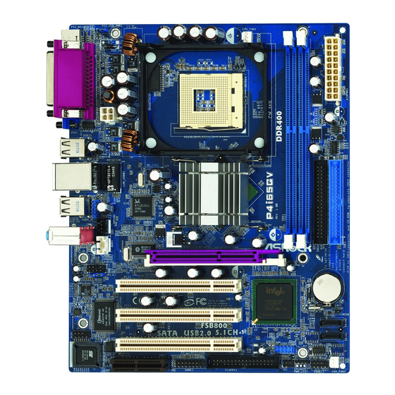
Page 10: Motherboard Layout
Infrared Module Header (IR1) CPU Fan Connector (CPU_FAN1) Floppy Connector (FLOPPY1) North Bridge Controller AMR Slot (AMR1) 184-pin DDR DIMM Slots (DDR1- 2, Dual Channel) 22 BIOS FWH Chip ATX Power Connector (ATXPWR1) COM Port Header (COM1) Primary IDE Connector (IDE1, Blue) -
Page 11: Asrock I/O Plus
1.5 ASRock I/O Plus Parallel Port USB 2.0 Ports (USB01) RJ-45 Port USB 2.0 Ports (USB23) Line In (Light Blue) VGA Port Line Out (Lime) PS/2 Keyboard Port (Purple) Microphone (Pink) PS/2 Mouse Port (Green) Shared USB 2.0 Ports (USB45) -
Page 12: Installation
Chapter 2 Installation P4i65GV is a Micro ATX form factor (9.6-in x 7.8-in, 24.4 cm x 19.8 cm) motherboard. Before you install the motherboard, study the configuration of your chassis to en- sure that the motherboard fits into it. Pre-installation Precautions Take note of the following precautions before you install motherboard com- ponents or change any motherboard settings. -
Page 13: Cpu Installation
CPU into the socket to avoid bending of the pins. Step 4. When the CPU is in place, press it firmly on the socket while you push down the socket lever to secure the CPU. The lever clicks on the side tab to indicate that it is locked. -
Page 14: Installation Of Memory Modules (Dimm)
Unlock a DIMM slot by pressing the retaining clips outward. Step 2. Align a DIMM on the slot such that the notch on the DIMM matches the break on the slot. The DIMM only fits in one correct orientation. It will cause permanent damage to the motherboard and the DIMM if you force the DIMM into the slot at incorrect orientation. -
Page 15: Expansion Slots (Pci, Amr, And Agi Slots)
Because the installed AMR card will occupy the same external connecting position with the PCI card installed in “PCI3” slot, you will no be able to install any PCI card in “PCI3” slot if an AMR card has already been installed in the AMR slot. -
Page 16: Easy Dual Monitor Feature
Note: To select +5VSB, it requires 2 Amp and higher standby current provided by power supply. (see p.10 No. 26) (see p.10 No. 25) Note: If the jumpers JL1 and JR1 are short, both the front panel and the rear panel audio connectors can work. Clear CMOS (CLRCMOS0, 2-pin jumper) 2-pin jumper (see p.10 No. -
Page 17: Onboard Headers And Connectors
FDD connector (33-pin FLOPPY1) (see p.10 No. 20) the red-striped side to Pin1 Note: Make sure the red-striped side of the cable is plugged into Pin1 side of the connector. Primary IDE connector (Blue) Secondary IDE connector (Black) (39-pin IDE1, see p.10 No. 8) (39-pin IDE2, see p.10 No. - Page 18 USB 2.0 Header ASRock I/O Plus accommo- dates 6 default USB 2.0 ports. If (9-pin USB67) those USB 2.0 ports on the I/O (see p.10 No. 15) panel are not sufficient, this USB 2.0 header is available to support 2 additional USB 2.0...
- Page 19 CPU Fan Connector Please connect a CPU fan cable to this connector and match (3-pin CPU_FAN1) the black wire to the ground pin. (see p.10 No. 4) ATX Power Connector Please connect an ATX power supply to this connector.
-
Page 20: Serial Ata (Sata) Hard Disks Installation
STEP 3: Connect one end of the SATA data cable to the motherboard’s SATA connector. STEP 4: Connect the other end of the SATA data cable to the SATA hard disk. Before you install OS into the SATA hard disk, you need to check and ensure the configuration of the OnBoard IDE Operate Mode option in BIOS setup is correct according to the condition of your system. -
Page 21: Bios Setup Utility
Power-On-Self-Test (POST) to enter the BIOS SETUP UTILITY, otherwise, POST will continue with its test routines. If you wish to enter the BIOS SETUP UTILITY after POST, restart the system by pressing <Ctl> + <Alt> + <Delete>, or by pressing the reset button on the system chassis. -
Page 22: Navigation Keys
To save changes and exit the BIOS SETUP UTILITY <ESC> To jump to the Exit Screen or exit the current screen 3.2 Main Screen When you enter the BIOS SETUP UTILITY, the Main screen will appear and display the system overview BIOS SETUP UTILITY Advanced... -
Page 23: Advanced Screen
3.3 Advanced Screen In this section, you may set the configurations for the following items: CPU Configuration, Chipset Configuration, ACPI Configuration, IDE Configuration, PCIPnP Configuration, Floppy Configuration, SuperIO Configuration, and USB Configuration. BIOS SETUP UTILITY H/W Monitor Boot Security Exit... -
Page 24: Chipset Configuration
If it shows “Locked”, then the item Ratio CMOS Set- ting will be hidden. If you use the ratio value to time the CPU frequency, it will be equal to the core speed of the installed processor. - Page 25 Flexibility Option The default value of this option is [Disabled]. It will allow better tolerance for memory compatibility when it is set to [Enabled]. Configure DRAM Timing by SPD Select [Enabled] will configure the following items by the contents in the SPD (Serial Presence Detect) device.
-
Page 26: Acpi Configuration
Use this item to enable or disable Ring-In signals to turn on the system from the power-soft-off mode. PCI Devices Power On Use this item to enable or disable PCI devices to turn on the system from the power-soft-off mode. PS/2 Keyboard Power On Use this item to enable or disable PS/2 keyboard to turn on the system from the power-soft-off mode. -
Page 27: Ide Configuration
When [Compatible Mode] is selected Combined Mode Option It allows you to select between [Pri IDE + SATA] and [SATA + Sec IDE]. If it is set to [Pri IDE + SATA], then the secondary IDE will not work. Likewise, if it is set to [SATA + Sec IDE], then the primary IDE will not work. - Page 28 [ARMD]: This is used for IDE ARMD (ATAPI Removable Media Device), such as MO. LBA/Large Mode Use this item to select the LBA/Large mode for a hard disk > 512 MB under DOS and Windows; for Netware and UNIX user, select [Disabled] to disable the LBA/Large mode.
-
Page 29: Pcipnp Configuration
Block (Multi-Sector Transfer) The default value of this item is [Auto]. If this feature is enabled, it will enhance hard disk performance by reading or writing more data during each transfer. PIO Mode Use this item to set the PIO mode to enhance hard disk performance by optimizing the hard disk timing. -
Page 30: Floppy Configuration
Use this item to enable or disable floppy drive controller. Serial Port Address Use this item to set the address for the onboard serial port or disable it. Configuration options: [Disabled], [3F8 / IRQ4], [2F8 / IRQ3], [3E8 / IRQ4], [2E8 / IRQ3]. - Page 31 Parallel Port Address Use this item to set the address for the onboard parallel port or disable it. Configuration options: [Disabled], [378], and [278]. Parallel Port Mode Use this item to set the operation mode of the parallel port. The default value is [ECP+EPP].
-
Page 32: Usb Configuration
“Auto” option will disable the legacy USB support. 3.4 Hardware Health Event Monitoring Screen In this section, it allows you to monitor the status of the hardware on your system, including the parameters of the CPU temperature, motherboard temperature, CPU fan speed, chassis fan speed, and the critical voltage. -
Page 33: Boot Screen
3.5 Boot Screen In this section, it will display the available devices on your system for you to config- ure the boot settings and the boot priority. BIOS SETUP UTILITY Main Advanced H/W Monitor Boot Security Exit 3.5.1 Boot Settings Configuration Boot From Network Use this item to enable or disable the Boot From Network feature. -
Page 34: Boot Device Priority
CD/DVD drives. 3.6 Security Screen In this section, you may set or change the supervisor/user password for the system. For the user password, you may also clear it. BIOS SETUP UTILITY... -
Page 35: Exit Screen
BIOS SETUP UTILITY. Discard Changes and Exit When you select this option, it will pop-out the following message, “Dis- card changes and exit setup?” Select [OK] to exit the BIOS SETUP UTILITY without saving any changes. Discard Changes When you select this option, it will pop-out the following message, “Dis-... -
Page 36: Software Support
This motherboard supports various Microsoft Windows operating systems: 98 SE / ME / 2000 / XP. Because motherboard settings and hardware options vary, use the setup procedures in this chapter for general reference only. Refer to your OS documentation for more information.
Need help?
Do you have a question about the P4I65GV and is the answer not in the manual?
Questions and answers