Table of Contents
Advertisement
Quick Links
Advertisement
Table of Contents

Related Manuals for Swytch Go


Summary of Contents for Swytch Go
- Page 1 Instruction Manual...
- Page 2 Version 001 Swytch Help Centre Got an accessory? Scan here for instructions. www.swytchbike.com/help/manuals/...
- Page 3 Please read this manual, it contains important safety information and guidelines on how to get the most out of your Swytch Kit. The full and most up-to-date instruction manual can be found online and should be consulted for any changes: swytchbike.com/manual/go...
- Page 4 When fitting the axle into the forks it is essentially that it fits tightly. If there is any movement, or if the axle does not fit into the forks then you must get in touch with our support team. Do not attempt any modification without consent from an official Swytch Bike representative. Tighten up before riding Whether it’s your first ride or your hundredth ride, please ensure all nuts, screws and...
- Page 5 Get in touch Before you ride your Swytch Bike for the first time, please be sure that it has been correctly assembled. You’ll find step-by-step instructions in the digital manual. For further help and support visit our help centre - support.swytchbike.com As required by the EPAC standard, the A-weighted emission sound pressure level from the Swytch kit does not exceed 70 dB(A).
-
Page 6: Table Of Contents
Table of Contents In the Box Installation Kit Checklist Motor Wheel Pedal Sensor Tools Required Power Pack Harness Know Your Kit Starting Your Ride Charging Maintenace... -
Page 7: In The Box
In the Box Kit Checklist Tools Required... -
Page 8: Kit Checklist
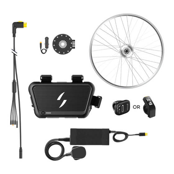
Kit Checklist Use this list to get all the parts ready before you start. Power Pack Motor Wheel Pedal Sensor 2A Charger (your selected option) Harness Cable Ties (your selected length) *Please note that this doesn’t include any optional accessories. -
Page 9: Tools Required
Tools Required You’ll need to use the following tools to install your Kit. Please note that these aren’t provided. Allen Key Set Tyre Levers Bike Pump Adjustable Spanner Ruler Scissors... -
Page 10: Installation
Installation Motor Wheel Pedal Sensor Power Pack Harness... -
Page 11: Motor Wheel
Motor Wheel Your Swytch motor wheel has been built to your specified size and incorporates the 250W motor hub that powers your bike. It’s important that it is securely fitted into your forks. 1. Remove your existing front wheel Turn your bike upside down. - Page 12 2. Prepare your Swytch motor wheel Fit your Swytch motor wheel with a Pump up the tyre to the tyre and inner tube using either your manufacturer’s suggested tyre existing set or a new set (advised). pressure. This is printed on the Use tyre levers to help you.
- Page 13 3. Fit the Swytch motor wheel onto your bike Loosen the screws slightly and slot The motor cable MUST be on the Swytch motor wheel into the the opposite side to the chain. fork dropouts. If you notice a gap between the Don’t file your forks to make the...
- Page 14 Fit the torque washer, flat washer, Note and axle nut as shown on both sides You will have received either a 9mm of your bike. Your bike fork dropouts or 10mm torque washer, depending should fit snugly around the lip of the on your wheel size.
- Page 15 4. Tighten the Swytch motor wheel Using a spanner tighten the nuts on Ensure 45 Nm of torque is used. both sides of the motor wheel. You’ll Visit swytchbike.com/manual need to temporarily take off the /45nm/ for support. rubber caps to do this.
- Page 16 The wheel should spin freely. When inserting the axle into the forks, ensure a snug fit. Contact our support team if there’s any looseness or fitting issue. Don’t modify without approval from a Swytch Bike representative.
-
Page 17: Pedal Sensor
Pedal Sensor The sensor is used to detect when you’re pedalling. Depending on what pedal sensor option you selected in your order portal, check the table below to find which page to find instructions to fit. Standard Pedal Sensor Page 18 (next page) Universal Pedal Sensor Page 23 Integrated Pedal Sensor... - Page 18 Standard Pedal Sensor A standard 2-piece magnetic disc, suitable for most standard cranks (e.g. square taper) and a pedal sensor. What’s included: Pedal sensor: Magnetic disc: Magnetic disc Retention ring...
- Page 19 2. Fit the magnetic disc Slot the magnetic disc around the Push and click together the two crank axle, behind the pedal arm, halves of the magnetic disc. It on the side of the bike opposite the should be a snug fit. chain.
- Page 20 4. Check the alignment Note The magnetic disc should run parallel to the frame. Check the If the magnetic disc slides around alignment by rotating the pedal when rotating the arm contact arm backwards and watch for any support for a universal pedal movement.
- Page 21 Foam spacer (add if necessary) 6.3 Target faces disc magnets 3mm gap Cable ties go through gaps Note If there isn’t enough space, cut off the plastic hinge piece of the sensor and mount directly using cable ties.
- Page 22 6. Finished...
- Page 23 Universal Pedal Sensor A universal 3-piece magnetic disc and pedal sensor, suitable for ANY crank. What’s included: Pedal sensor: Magnetic disc regular: Bolt Magnetic disc Retention ring Inserts provided: Easy fit thin inserts (2 pieces) Easy fit regular inserts (2 pieces)
- Page 24 1. Determine if you need the inserts for your bike Use a ruler to measure the gap between the end of the pedal arm and the start of the bike frame on the left side of the bike (opposite side to the chain). Pedal arm Check the table below Use this table to calculate which...
- Page 25 3. Fit the correct inserts (if necessary) Fit together the inserts with the female parts of the magnetic disc arm. The inserts can slot in facing either orientation, but ensure the spiral of the teeth aligns as shown. 4. Determine if you need to flip the leg of the magnetic disc Check which pedal arm your bike has from the two options below.
- Page 26 5. Flip the leg of the magnetic disc (indented pedal arms only) Bolt out Unscrew the bolt using a 2.5mm Allen key. Take out the bolt and the leg. Leg out Side without ‘Working Surface’ written on Flip the leg 180 degrees to match image.
- Page 27 6. Fit the magnetic disc Slot the magnetic disc around the Push and click together the two crank axle, behind the pedal arm, halves of the magnetic disc. on the side of the bike opposite the Note chain. If you have inserts, the same Check the side of the disc with instructions apply.
- Page 28 8. Secure the arm with cable ties Slightly tighten cable tie the magnetic disc arm to the inside of your pedal arm in at least two places. Note For narrow pedal arms, thread the cable ties through the holes to improve and tighten the grip.
- Page 29 9. Check the alignment The magnetic disc should run Once the alignment is correct, parallel to the frame. Check the tighten the cable ties and bolts. alignment by rotating the pedal arm backwards and watching for any movement.
- Page 30 Foam spacer (add if necessary) 10.3 Target faces disc magnets 3mm gap Cable ties go through gaps Note If there isn’t enough space, cut off the plastic hinge piece of the sensor and mount directly using cable ties.
- Page 31 11. Finished...
- Page 32 Integrated Sensor Integrated sensor for standard cranks (e.g. square taper). It requires the pedal arm to be removed and replaced for installation and the bottom brackets to have 20 splines. You will need: Crank extractor Either 8mm Allen Key or 14mm socket 1.
- Page 33 2. Unscrew the crank arm’s bolt Use the Allen key or socket to remove the bolt from the crank, working on the side opposite to the chain. Hold with hand to keep from moving Rotate anti-clockwise 3. Tighten the crank extractor bolt Rotate the crank extractor’s bolt clockwise until it is securely tightened.
- Page 34 4. Rotate the extractor and remove the crank arm Note Rotate the handle of the crank extractor clockwise and then remove the arm. This often takes quite a lot of force to rotate. Hold with hand to keep from moving Rotate clockwise 5.
- Page 35 6. Reinstall the crank Identify the correct position to Reattach the original bolt and reinstall your crank and slot it back on. tighten using the Allen key to the manufacturer’s torque specification. Once fully tightened, the pedal arm shouldn’t touch the sensor. Hold with hand to keep from moving Rotate clockwise...
-
Page 36: Power Pack
Power Pack This is the Swytch GO Power Pack. It has Li-ion cells inside that provide the energy for the Kit. Swytch GO comes in three different capacitities: GO 187Wh, GO+ 281Wh and GO++ 378Wh. 3 x Straps Connector port... - Page 37 Determine where you wish to fit your Power Pack Note Decide where to fit your Power Pack on your bike, considering whether you chose Don’t block the connector port by the standard or long connector harness. facing it into the frame. Standard Our standard connector harness allows you to position the Power Pack within the frame.
- Page 38 Secure the Power Pack Secure your Power Pack to your Three straps must be desired location on your bike by used to secure it properly. using the three velcro straps. Use the buckle on each strap to Check your brakes secure the Power Pack.
- Page 39 Cut the straps to size Trim the three straps with scissors to Ensure that the strap eliminate any overlapping material. has enough length to be securely fastened to your bike’s frame. Apply protective tape To minimise the chance of damaging your bike’s paint, affix clear protective tape anywhere the Power Pack makes contact with the frame.
-
Page 40: Harness
Harness The harness connects the Power Pack to the Swytch Kit system, it has five connectors coming out of it all with a different purpose. Note The harness comes with a pre-installed no display dongle for display-free operation. If you have purchases an additional display, just unplug this and plug in the display. - Page 41 2. Connect the pedal sensor to the harness To connect the waterproof connector, find the arrow on each connector and align. Once the arrows are lined up, push together until no colour is visible. Pedal Sensor Colour visible No colour visible 3.
- Page 42 Route the harness and cables The diagrams below illustrate different Ensure the cable routing cable routings for Power Pack placement doesn’t affect any part of options. Please follow the diagrams when the bike’s drive train, routing your cables. steering or pedalling. Standard Route the cables via the shortest path to the bike’s headtube, where the splitter should be positioned.
- Page 43 5. Secure the harness and cables Note Secure all cabling to the frame of the bike using the cable ties that Follow the existing cable routing of were provided. your bike and position the cables behind the frame where possible. Securely attach the motor Secure the Pedal sensor Fasten the splitter to...
- Page 44 Know Your Kit Starting Your Ride Charging Maintenance...
- Page 45 Starting Your Ride To start your ride first make sure Start pedaling, the pedal sesnor all cables are connected fully and will flash and the power will begin the magnetic disc has been fitted to kick in. correctly. Note Press the On/Off button on the If you have connected a display, front of the Power Pack, the LEDs these instructions will slightly differ.
- Page 46 Charging Turn your Power Pack Off. When the light on the charging brick changes from red to green Plug the charger end into the the Power Pack is fully charged connector and should be unplugged. Don’t charge for extended periods of time. Only use the charger provided to charge the battery.
- Page 47 Maintenance Interval Swytch Kit Bike (whichever is first) Every ride Recharge the Power Pack Tyre pressure If installed, test the brake Check tyres for debris/ sensors operate normally thorns Check brakes Monthly Top up battery charge if Adjust brakes storing over winter...
- Page 48 Swytch Technology Ltd, Unit 2A 455 Wick Lane London E3 2TB...
- Page 49 Scan here for the Swytch Help Centre.
Need help?
Do you have a question about the Go and is the answer not in the manual?
Questions and answers