Advertisement
Quick Links
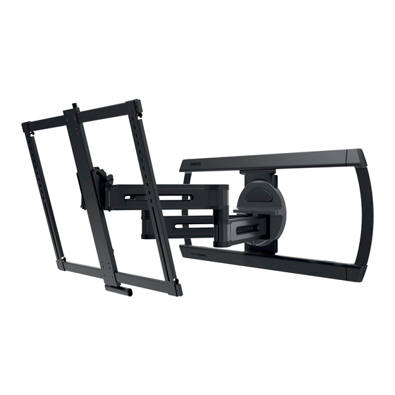
BLF 528-B1
INSTRUCTION MANUAL
Texto en Español, página 18
WE'RE HERE TO HELP
Want to watch a video that
shows how easy this is?
Watch it now at:
SANUS.com/3168
Get it right the first time.
HeightFinder™ shows you
where to drill.
Use it now:
SANUS.com/1172
Our live US-based install
experts are standing by to help.
Call us at:
+1 (800) 359-5520
Or, chat at:
SANUS.com/chatSP
Advertisement

Related Manuals for LEGRAND SANUS BLF528-B1


Summary of Contents for LEGRAND SANUS BLF528-B1
- Page 1 BLF 528-B1 INSTRUCTION MANUAL Texto en Español, página 18 WE’RE HERE TO HELP Want to watch a video that Get it right the first time. Our live US-based install shows how easy this is? HeightFinder™ shows you experts are standing by to help. where to drill.
-
Page 2: Wall Construction
IMPORTANT SAFETY INSTRUCTIONS – PLEASE READ MANUAL PRIOR TO USE – SAVE THESE INSTRUCTIONS Please read through these instructions completely to be sure you’re comfortable with this easy install process. Check your TV owner’s manual to see if there are any special requirements for mounting your TV. If you do not understand these instructions or have doubts about the safety of the installation, assembly or use of this product, contact Customer Service: +1 (800) 359-5520. -
Page 3: Before You Begin
Dimensions TV INTERFACE 7.9in 200mm 3.9in 100mm 20.87in 15.7in 400mm 530mm 23.6in 600mm 17.78in 451.6mm WALL PLATE TOP VIEW - EXTENDED SIDE VIEW - EXTENDED 36.2in 28 in 920mm 711mm 24.0in 610mm 15.7 in 46deg 46deg 13.8 in 11.5in 398mm 350mm 291mm 15°... -
Page 4: Supplied Parts And Hardware
Supplied Parts and Hardware WARNING: This product contains small items that could be a choking hazard if swallowed. Before starting assembly, verify all parts are included and undamaged. If any parts are missing or damaged, do not return the damaged item to your dealer; contact Customer Service. Never use damaged parts! NOTE: Not all hardware included will be used. - Page 5 STEP 1 Attach TV Bracket to TV 1.1 Select TV Screw Diameter 1.2 Select TV Screw Length and Spacers Only one screw size fits your TV. NO SPACER SPACER NEEDED • Flat Back TV • Flat Back TV • Rounded or Irregular Back TV with extra space needed [for deep inset holes or cable interference] [TV brackets NOT resting flat on your TV]...
- Page 6 Align with your TV's mounting hole pattern (VESA).
- Page 7 NO SPACER SPACER NEEDED NOTE: Hanging tab is oriented to the TOP of your TV. CAUTION: Avoid potential personal injuries and property damage! DO NOT use power tools for this step. Tighten the screws only enough to secure the TV brackets to the TV.
-
Page 8: Wood Stud Installation
STEP 2A Attach Wall Plate Wood Stud Installation CAUTION: Avoid potential personal injury or property damage! ● Drywall covering the wall must not exceed 5/8 in. (16 mm) ● Minimum wood stud size: nominal 2 x 4 in. (51 x 102 mm) actual 1½ x 3½ in. (38 x 89 mm) ●... - Page 9 STEP 2B Attach Wall Plate Solid Concrete or Concrete Block Installation CAUTION: Avoid potential personal injury or property damage! (Center) ● Mount wall plate directly onto concrete surface (no wall covering) ● Minimum solid concrete thickness: 8 in. (203 mm) ●...
- Page 10 STEP 3 Hang TV onto Wall Plate 3.1 Attach Arm Assembly to Wall Plate HEAVY! You may need assistance with this step. CAUTION: Avoid potential personal injury or property damage! For CONCRETE APPLICATIONS: The arm assembly MUST remain centered in wall plate NOTE: For WOOD STUD APPLICATIONS, the arm assembly...
- Page 11 CAUTION: Avoid potential personal injury or property damage! Locking screws must be tightened to secure the arm assembly 3.2 Attach TV to Arm Assembly HEAVY! You may need assistance with this step.
- Page 12 CAUTION: Avoid potential personal injury or property damage! Locking screw must be installed to secure the TV to the arm assembly 1. Loosen the screw 2. Adjust handle enough to grab 3. Tighten the screw from the front of your TV.
-
Page 13: Manage Cables
Manage Cables IMPORTANT: Fully extend arm assembly to ensure enough slack in cables. 1. Slide to remove the cable covers 2. Route your cables through the arm assembly 3. Reattach the cable covers over the cables. -
Page 14: Level Adjustment
TV Adjustments MOVING YOUR TV EXTEND / RETRACT TILT SWIVEL LEVEL ADJUSTMENT CAUTION: Screw MUST be loosened before turning screw CAUTION: Avoid potential personal injury or property damage! Always make sure your securement screw is tightened, so the TV is securely fastened to the arm assembly. -
Page 15: Tilt Adjustment
TILT ADJUSTMENT Your TV should adjust easily when moved, then stay in place. If your TV is too loose or too tight, adjust the side tension knob by hand or use hex for additional tightening. NOTE: Once your TV is in place, tighten the tension knob to prevent unwanted movement. - Page 16 LATERAL SHIFT HEAVY! You may need assistance with this step. CAUTION: Avoid potential injuries or property damage! DO NOT adjust the arm position from center for CONCRETE APPLICATIONS. MUST remain centered in wall plate for all concrete applications! For WOOD STUD APPLICATIONS, 1.
-
Page 17: Removing The Tv
EXTEND / RETRACT -- ONLY IF NECESSARY Your TV should adjust easily when moved, then stay in place. ONLY if needed, adjust the extension/retraction arm tension with screw using hex key CAUTION: Avoid potential personal injury or property damage! DO NOT remove bolts , only turn enough for slight adjustment. - Page 18 INSTRUCCIONES IMPORTANTES DE SEGURIDAD ESPAÑOL – – LEA TODO ESTE MANUAL ANTES DE UTILIZAR ESTE PRODUCTO GUARDE ESTAS INSTRUCCIONES Lea atentamente estas instrucciones en su totalidad para asegurarse de que está familiarizado con el sencillo proceso de instalación. Consulte igualmente el manual de su televisor para conocer si existen requisitos especiales para el montaje de su aparato. Si no entiende las instrucciones o si tiene dudas acerca de la seguridad de la instalación, el montaje o el uso del producto, póngase en contacto con el Servicio de Atención al Cliente o llame +1 (800) 359-5520 a nuestro servicio técnico al número...
- Page 19 PASO 2A Fijar la placa mural para montantes de madera VER PÁGINA 6 PRECAUCIÓN: Evite lesiones personales y daños materiales. El yeso que recubre la pared no debe exceder los 16 mm (5/8'') ● ● Tamaño mínimo del montante de madera: común 51 mm x 102 mm (2'' x 4'') nominal 38 mm x 89 mm (1 ½'' x 3 ½'') ●...
- Page 20 Legrand AV Inc. and its a iliated corporations and subsidiaries (collectively, “Legrand”), intend to make this manual accurate and complete. However, Legrand makes no claim that the information contained herein covers all details, conditions, or variations. Nor does it provide for every possible contingency in connection with the installation or use of this product. The information contained in this document is subject to change without notice or obligation of any kind. Legrand makes no representation of warranty, expressed or implied, regarding the information contained herein.
Need help?
Do you have a question about the SANUS BLF528-B1 and is the answer not in the manual?
Questions and answers