Cisco Aironet 3800 Series Getting Started Manual
Hide thumbs
Also See for Aironet 3800 Series:
- Deployment manual (66 pages) ,
- Deployment manual (10 pages)

Related Manuals for Cisco Aironet 3800 Series


Summary of Contents for Cisco Aironet 3800 Series
- Page 1 ETTING TARTED UIDE Cisco Aironet 3800 Series Access Points First Published: December 12, 2016...
- Page 2 About this Guide About the Access Point Safety Instructions Unpacking AP Views, Ports, and Connectors Preparing the AP for Installation Installation Overview Performing a Pre-Installation Configuration Mounting and Grounding the Access Point Powering the Access Point Configuring and Deploying the Access Point Checking the Access Point LEDs Miscellaneous Usage and Configuration Guidelines Related Documentation...
- Page 3 The 3800 series access point is referred to as access point or AP in this document. About the Access Point The Cisco Aironet 3800 Series Wi-Fi access points provide 802.11ac Wave 2 with Multi User MIMO (MU MIMO). This AP series offers integrated and external antenna options, with a dedicated 5 GHz radio and a flexible radio that can be configured as a 2.4 GHz radio (default) or as an additional...
- Page 4 • Multiuser Multiple-Input Multiple-Output (MU-MIMO) technology with 3 spatial streams. • Cross-AP Noise Reduction, a Cisco innovation that enables APs to intelligently collaborate in real time about RF conditions so that users connect with optimized signal quality and performance.
- Page 5 You need to verify whether the AP model you have is approved for use in your country. To verify approval and to identify the regulatory domain that corresponds to a particular country, visit http://www.cisco.com/go/aironet/compliance. Not all regulatory domains have been approved. As and when they are approved, this compliance list will be updated.
- Page 6 13 dBi (5 GHz) 1. For the USA, the UNII-1 channels can be used only indoors. Cisco also provides the following external antenna accessories: • 5 ft Low Loss RF cable with RP-TNC and N-type Connectors (AIR-CAB005LL-R-N/=). You will need four of these.
- Page 7 Translated versions of the following safety warnings are provided in the translated safety warnings document that is shipped with your access point. The translated warnings are also in the Translated Safety Warnings for Cisco Aironet Access Points, which is available on Cisco.com. Warning IMPORTANT SAFETY INSTRUCTIONS This warning symbol means danger.
- Page 8 Step 2 Verify that you have received the items listed below. If any item is missing or damaged, contact Step 3 your Cisco representative or reseller for instructions. The access point – Mounting bracket (selected when you ordered the access point) –...
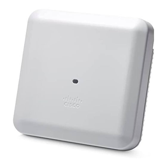
- Page 9 AP Views, Ports, and Connectors Figure 1 Face of the 3802I Model Status LED Location of the module connector port on the base of the AP Location of the ports and connectors on the head of the AP...
- Page 10 Figure 2 Face of the 3802E and 3802P Models Dual-band antenna connector A Status LED Dual-band antenna connector B Location of the ports and connectors on the head of the AP Dual-band antenna connector C Location of the Smart antenna connector port on the right side of the AP Dual-band antenna connector D Location of the module connector port on...
- Page 11 Figure 3 Ports and Connections on the Head of the AP Kensington lock slot AUX / Gigabit Ethernet port Mode button PoE / mGig port Console port 48 VDC power port USB port...
- Page 12 Figure 4 AP Module Connector Port on the Base...
- Page 13 Figure 5 Smart Antenna Connector on the Right Side of the 3802E and P Models 354568 For more information on the Smart antenna connector, see the “What is a Smart Antenna connector?” section on page...
-
Page 14: Table Of Contents
Cisco recommends that you make a site map showing access point locations so that you can record the device MAC addresses from each location and return them to the person who is planning or managing your wireless network. -
Page 15: Performing A Pre-Installation Configuration
Network” section on page 22 for details. The following Pre-Installation Configuration procedure given does not include configuring Link Aggregation. For information on configuring Link Aggregation, see the Cisco Wireless LAN Controller Configuration Guide, Release 8.2, at this URL: http://www.cisco.com/c/en/us/td/docs/wireless/controller/8-2/config-guide/b_cg82.html The pre-installation configuration setup is illustrated in... -
Page 16: Step 1
Controller Configuration Guide for the release you are using, for additional information. c. Set the Cisco wireless LAN controller as the master so that new access points always join with d. Make sure DHCP is enabled on the network. The access point must receive its IP address through DHCP. - Page 17 Note When you are installing a Layer 3 access point on a different subnet than the Cisco wireless LAN controller, be sure that a DHCP server is reachable from the subnet on which you will be installing the access point, and that the subnet has a route back to the Cisco wireless LAN controller.
-
Page 18: Mounting And Grounding The Access Point
Mounting and Grounding the Access Point Cisco Aironet 3800 series access points can be mounted in several configurations – on a suspended ceiling, on a hard ceiling or wall, on an electrical or network box, and above a suspended ceiling. - Page 19 Figure 7 Locking the AP to the Bracket and Power Cable Routing Power cable routing Position of the lock for locking the AP to the bracket...
-
Page 20: Powering The Access Point
Configuring and Deploying the Access Point This section describes how to connect the access point to a wireless LAN controller. Because the configuration process takes place on the controller, see the Cisco Wireless LAN Controller Configuration Guide for additional information. - Page 21 • DHCP server discovery—This feature uses DHCP option 43 to provide controller IP addresses to the access points. Cisco switches support a DHCP server option that is typically used for this capability. For more information about DHCP option 43, see the “Configuring DHCP Option 43”...
-
Page 22: Step 1
Cisco wireless LAN controller. Also, if the access point is not on the same subnet as the Cisco wireless LAN controller, be sure that there is a properly configured DHCP server on the same subnet as the access point. See the “Configuring DHCP Option 43”... - Page 23 Checking the Access Point LEDs Regarding LED status colors, it is expected that there will be small variations in color intensity Note and hue from unit to unit. This is within the normal range of the LED manufacturer’s specifications and is not a defect. The access point status LED indicates various conditions and are described in Table Table 2...
- Page 24 Miscellaneous Usage and Configuration Guidelines Using the Mode Button Using the Mode button (see Figure 3) you can: • Reset the AP to the default factory-shipped configuration. • Clear the AP internal storage, including all configuration files. To use the mode button, press, and keep pressed, the mode button on the access point during the AP boot cycle.
- Page 25 2500 series controllers and the Controller Network Module within the Cisco 28/37/38xx Series Integrated Services Routers. The maximum number of access points varies for the Cisco WiSM2, depending on which Note controller software release is being used.
- Page 26 Important Information for Controller-based Deployments Keep these guidelines in mind when you use 3802 series access points: • The access point can only communicate with Cisco wireless LAN controllers. • The access point does not support Wireless Domain Services (WDS) and cannot communicate with WDS devices.
- Page 27 • Length: Number of controller IP addresses * 4 • Value: List of WLC management interfaces To configure DHCP Option 43 in the embedded Cisco IOS DHCP server, follow these steps: Enter configuration mode at the Cisco IOS CLI. Step 1...
- Page 28 10.126.126.2 and 10.127.127.2. The type is f1(hex). The length is 2 * 4 = 8 = 08 (hex). The IP addresses translate to 0a7e7e02 and 0a7f7f02. Assembling the string then yields f1080a7e7e020a7f7f02. The resulting Cisco IOS command added to the DHCP scope is option 43 hex f1080a7e7e020a7f7f02.
- Page 29 Flexible Radio Assignment mode, allowing dual 5 GHz and Wireless Security Monitoring modes. To connect to any supported RP-TNC connector-type external antenna to the Smart antenna connector, use the DART cable connector AIR-CAB002-DART-R= (see Figure 9), which is to be procured separately from Cisco.
- Page 30 1 Gbps on all cabling infrastructure. Cisco Multigigabit technology allows you to achieve bandwidth speeds from 1 to 10 Gbps over traditional Cat 5e cabling or newer. The Cisco AP3802 supports up to 5 Gbps using mGig.
- Page 31 What is a ClientLink 4.0? How is it different from Tx-Beamforming? Cisco ClientLink 4.0 is a beamforming capability built into Cisco Aironet wireless LAN access points. When the access point concentrates signals toward the receiving client, that client is better able to hear the AP’s transmission, and so throughput is greater.
- Page 32 Related Documentation All user documentation for the Cisco Aironet 3800 series access point is available at the following URL: http://www.cisco.com/c/en/us/support/wireless/aironet-3800-series-access-points/tsd-products-suppor t-series-home.html For detailed information and guidelines for configuring and deploying your access point in a wireless network, see the following documentation: •...
- Page 33 Declarations of Conformity and Regulatory Information This section provides declarations of conformity and regulatory information for the Cisco Aironet 3800 Series Access Points. You can find additional information at this URL: www.cisco.com/go/aironet/compliance Manufacturers Federal Communication Commission Declaration of Conformity Statement...
- Page 34 The Part 15 radio device operates on a non-interference basis with other devices operating Caution at this frequency when using the integrated antennas. Any changes or modification to the product not expressly approved by Cisco could void the user’s authority to operate this device. VCCI Statement for Japan...
- Page 35 Guidelines for Operating Cisco Aironet Access Points in Japan This section provides guidelines for avoiding interference when operating Cisco Aironet access points in Japan. These guidelines are provided in both Japanese and English. Japanese Translation 03-6434-6500 English Translation This equipment operates in the same frequency bandwidth as industrial, scientific, and medical devices such as microwave ovens and mobile object identification (RF-ID) systems (licensed premises radio stations and unlicensed specified low-power radio stations) used in factory production lines.
- Page 36 Material Safety Law prohibits the use of UL-certified cables (that have the “UL” shown on the code) for any other electrical devices than products designated by CISCO. The use of cables that are certified by Electrical Appliance and Material Safety Law (that have “PSE” shown on the code) is not limited...
- Page 37 Industry Canada Access Point Models Certification Number AIR-AP3802I-A-K9 2461B-102100 AIR-AP3802E-A-K9 2461B-102099 AIR-AP3802P-A-K9 2461B-102101 Canadian Compliance Statement This device complies with Industry Canada licence-exempt RSS standard(s). Operation is subject to the following two conditions: (1) this device may not cause interference, and (2) this device must accept any interference, including interference that may cause undesired operation of the device.
- Page 38 Antenna Type Antenna Gain Antenna Impedance Dual-band Omni 2/4 dBi 50 ohms Dual-band Dipole 2/4 dBi 50 ohms Dual-Band Directional 6/6 dBi 50 ohms Operation in the band 5150-5250 MHz is only for indoor use to reduce the potential for harmful interference to co-channel mobile satellite systems.
- Page 39 Declaration of Conformity with regard to the R&TTE Directive 1999/5/EC & Medical Directive 93/42/EEC...
- Page 40 The following standards were applied: EMC—EN 301.489-1 v1.9.2; EN 301.489-17 v2.2.1 Health & Safety—EN60950-1: 2006; EN 50385: 2002 Radio—EN 300 328 v 1.8.1; EN 301.893 v 1.7.1 The conformity assessment procedure referred to in Article 10.4 and Annex III of Directive 1999/5/EC has been followed.
- Page 41 This section contains information on compliance with guidelines related to RF exposure. Generic Discussion on RF Exposure The Cisco products are designed to comply with the following national and international standards on Human Exposure to Radio Frequencies: • US 47 Code of Federal Regulations Part 2 Subpart J •...
- Page 42 As such the systems are designed to be operated as to avoid contact with the antennas by the end user. It is recommended to set the system in a location where the antennas can remain at least a minimum distance as specified from the user in accordance to the regulatory guidelines which are designed to reduce the overall exposure of the user or operator.
- Page 43 Separation Distance - 3800I and 3800E Distance Limit 0.6 mW/cm 30 cm (12 inches) 1.00 mW/cm Separation Distance - 3800P Distance Limit 0.57 mW/cm 30 cm (12 inches) 1.00 mW/cm The US Food and Drug Administration has stated that present scientific information does not indicate the need for any special precautions for the use of wireless devices.
- Page 44 Separation Distance - 3800P Frequency Distance Limit 2.04 W/m 30 cm (12 inches) 5.4 W/m 2.4 GHz 3.36 W/m 9.2 W/m 5 GHz Health Canada states that present scientific information does not indicate the need for any special precautions for the use of wireless devices. They recommend that if you are interested in further reducing your exposure you can easily do so by reorienting antennas away from the user, placing the antennas at a greater separation distance than recommended, or lowering the transmitter power output.
- Page 45 Additional Information on RF Exposure You can find additional information on the subject at the following links: • Cisco Systems Spread Spectrum Radios and RF Safety white paper at this URL: http://www.cisco.com/warp/public/cc/pd/witc/ao340ap/prodlit/rfhr_wi.htm • FCC Bulletin 56: Questions and Answers about Biological Effects and Potential Hazards of Radio Frequency Electromagnetic Fields •...
- Page 46 Chinese Translation...
- Page 47 English Translation Administrative Rules for Low-power Radio-Frequency Devices Article 12 For those low-power radio-frequency devices that have already received a type-approval, companies, business units or users should not change its frequencies, increase its power or change its original features and functions. Article 14 The operation of the low-power radio-frequency devices is subject to the conditions that no harmful interference is caused to aviation safety and authorized radio station;...
- Page 48 Operation of Cisco Aironet Access Points in Brazil This section contains special information for operation of Cisco Aironet access points in Brazil. Access Point Models: AIR-AP3802I-Z-K9...
- Page 49 Figure 10 Brazil Regulatory Information Portuguese Translation Este equipamento opera em caráter secundário, isto é, não tem direito a proteção contra interferência prejudicial, mesmo de estações do mesmo tipo, e não pode causar interferência a sistemas operando em caráter primário. English Translation This equipment operates on a secondary basis and consequently must accept harmful interference, including interference from stations of the same kind.
- Page 50 © 2016 Cisco Systems, Inc. All rights reserved. Cisco and the Cisco logo are trademarks or registered trademarks of Cisco and/or its affiliates in the U.S. and other countries. To view a list of Cisco trademarks, go to this URL: www.cisco.com/go/trademarks. Third-party trademarks mentioned are the property of their respective owners. The use of the word partner does...
Need help?
Do you have a question about the Aironet 3800 Series and is the answer not in the manual?
Questions and answers