Advertisement
- 1 List of E-Bike Component Names
-
2
Mechanical Components Operation, Maintenance, & Safety
- 2.1 Riding Conditions
- 2.2 Saddle Set-Up, Adjustment
- 2.3 Safe Cycling and Safety Tips
- 2.4 Routine Maintenance Check and Lubrication
-
2.5
Assembly Instructions
- 2.5.1 Step 1: Unpacking Your Bike
- 2.5.2 Step 2: Front Wheel & Front Fender Installation
- 2.5.3 Step 3: Seat Assembly
- 2.5.4 Step 4: Handlebar Assembly
- 2.5.5 Step 5: Installing Pedals
- 2.5.6 Step 6: Brake Adjustments
- 2.5.7 Step 7: Derailleur Gears Maintenance and Adjustment
- 2.5.8 Step 8: Check Before Riding
-
3
Electrical Components Operation, Maintenance, & Safety
- 3.1 Important Safety Precautions
- 3.2 Operation
- 3.3 Battery Installation & Usage.
-
3.4
LCD Display and Functions
- 3.4.1 Material and Color
- 3.4.2 Button Definition
- 3.4.3 ON/OFF
- 3.4.4 Current Display
- 3.4.5 Riding Mode Selection
- 3.4.6 Speed Display
- 3.4.7 KM/H & MPH
- 3.4.8 Backlight Indicator
- 3.4.9 6KM/H Work
- 3.4.10 PAS Level Selection
- 3.4.11 Error Code Indicator
- 3.4.12 SET Operation
- 3.4.13 Distance Indicator
- 3.4.14 Trip Time Indicator
- 3.4.15 Battery Indicator
- 3.4.16 Auto Sleep After 5 Minutes
- 3.5 Using and Maintaining the Battery
- 3.6 Using and Maintaining the Battery Charger
- 3.7 Using and Maintaining the Electric Hub Motor
- 3.8 Maintaining the Controller
- 3.9 Maintaining the Power-Off Control of the Brake Lever
- 3.10 Maintaining the Throttle Lever
- 4 Simple Troubleshooting
- 5 Electric Circuit Diagram
- 6 Main Technical Specification Sheet
- 7 Common Problems & Solutions
- 8 Error Code Table
- 9 Documents / Resources
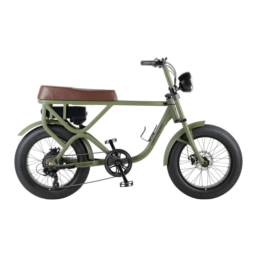
List of E-Bike Component Names

Fig. 1 Electric Bicycle
- Tires & Tubes
- Rims
- Spokes
- Front Hub with QR
- Front Mechanical Disk Brake
- Front Fork
- Front Mudguard (Fender)
- Front Light
- Brake Cable
- Electric Brake Lever
- Throttle
- Saddle
- Frame
- Pedal
- Crank Set
- Chain
- Rear Derailleur
- Rear Pedal Plate
- Freewheel
- Battery
- Display
Please read this instruction manual carefully and thoroughly before riding. It contains important information on safety, and maintenance. It is the owner's responsibility to read this manual before riding. Keep this manual for future reference.
This user's instruction manual includes two sections:
- Mechanical Operation, and
- Electric Operation.
These instructions apply to electric bike models with following equipment:
Mechanical Components Operation
- Derailleur with Disc Brakes
For mechanical equipment, an electric bicycle differs slightly from a non-electric bike.
Electrical Components Operation
- The battery-pack mounted in the rear carrier or on the down tube
- The motor in the rear wheel hub or front wheel hub
- The controller box next to the battery or integrated into the battery-pack
- Handlebar-mounted Display Panel operations.
Mechanical Components Operation, Maintenance, & Safety
Riding Conditions
This pedal electric assistance bicycle is designed for riding on road, or paved surfaces where the tires have firm contact with the riding surface. This e-bike must be properly maintained according to the instructions found within this manual. The maximum weight of the rider and load is 2201bs (100kgs).

The owner/rider assumes the risk for personal injury, damage, or losses. If the conditions in this manual are breached, the warranty will be void automatically.
Saddle Set-Up, Adjustment
The Valen saddle is installed from the factory. It is a fixed position saddle (similar to a traditional motorcycle seat), and is not adjustable.
The rider moves/slides forwards/ back and a bit from side-to-side to comfortably and safely ride and control the ebike.
Safe Cycling and Safety Tips
Pre-Ride Check Points
Before you ride your pedal electric assistance bicycle always make sure it is in a safe operating condition. Particularly check that your:
- Nuts, bolts, quick-release and parts are fastened tight, not worn, or damaged.
- Riding position is comfortable and unencumbered.
- Brakes are operating effectively.
- Steering is free with no excessive play.
- Wheels run true and hub bearings are correctly adjusted.
- Wheels are properly secured and locked to frame/fork.
- Tires are in good condition and inflated to correct pressure (tire pressure in on tire sidewall - do not exceed max tire pressure).
- Pedals are securely tightened to pedal cranks.
- All reflectors are in position and secure.
After you have made any adjustment to your electric bicycle, check that all nuts and bolts are securely tightened and cables are free from kinks and fixed securely to the electric bicycle frame. Every six months, your electric bicycle should be professionally checked to ensure that it is in correct and safe working order. It is the responsibility of the rider to ensure all parts are in working order prior to riding this electric bicycle.
What Never To Do When Riding
NEVER ride without wearing an approved helmet, which must meet USA/ European (CPSC/EN) standards. Always comply with the local laws and ordinances.
- NEVER ride on the same side of the road as oncoming traffic.
- NEVER carry a passenger, this bicycle is designed for a single rider only.
- NEVER hang item(s) over the handlebars, this could interfere with steering or catch in the front wheel causing a crash.
- NEVER hold on to another motor vehicle or bicycle.
- NEVER ride too close to another vehicle - keep your distance and awareness.
Wet Weather Riding: Your bike's brakes do not work as well under wet or icy conditions as they do under dry conditions. The braking distance in wet weather will be longer than that in dry conditions. Take special precautions in wet weather to assure safe stopping. Ride slower than normal and apply your brakes well in advance of anticipated stops.
Night Riding: Do not ride at night. If you have to be on your e-bike at night or in low-light conditions, always comply with laws and regulations (local and otherwise) for bicycle lighting. Use approved headlights (white), taillights (red) properly affixed to your e-bike in addition to all-around reflectors. For additional safety, wear light colored clothing with reflective stripes, or safety yellow or safety orange clothing. Check that the reflectors are firmly secured in the correct position and clean and not obscured. Damaged reflectors must be replaced immediately.
Routine Maintenance Check and Lubrication
As with all mechanical components, your bicycle is subjected to wear and stress. Different materials and components may react to wear or fatigue in different ways. If the design life of a component has been exceeded it may suddenly fail, possibly causing injuries to the rider. Any types of cracks, scratches, or change of coloring in highly stressed areas indicate that the life of the component has been reached and it should be replaced immediately.
Always inspect your bicycle before every ride.
Use only genuine replacement parts, particularly for safety-critical components, installed by a professional bicycle mechanic. To keep your electric bicycle functioning well, the following routine maintenance lubrication is necessary (refer to Fig. 2):

Fig. 2
Half-Yearly: Remove, clean, and lubricate chain, derailleur(s), cog set, and all cables. Check and replace as required.
Weekly (or as needed): Wash bicycle with warm soapy water. Dry with a soft, nonabrasive cloth. Do not use strong chemicals or abrasives. Do not use a highpressure washer. Inspect your bicycle while cleaning.
01 - Tires
Check for cuts and wear maintain pressure indicated on tires wall for maximum efficiency.
02 03 - Wheel
Check that axles are sealed and secured properly. Rim should be kept free from wax, oil, grease and glue. Check for loosed or missing spokes. (see warning below)
04 - Wheel Hub
Grease bearing monthly. Adjust cones to avoid free play side to side.
05 - Brake
Lightly oil exposed cables monthly. Maintain adjustment and replace brake blocks when worn, brake cables when frayed.
06 - Fork
Dealer adjustment only.
07 - Mudguard
Check the mudguards are clean and tight. Ensure the mudguard are secure and undamaged. Replace if necessary.
08 - Battery Light
Ensure the front and rear battery light are secure and undamaged, Replace if necessary.
10 - Handlebar
Check handlebar bolt is tight. Check brake lever securely mounted to bars and brakes stop smoothly and efficiently.
12 - Saddle
Ensure the saddle is undamaged, replace if necessary.
14 - Pedals
Lightly oil bearings monthly.
15 - Cranks
Keep light oiled weekly, clean and lubricate half yearly.
16 - Chain
Keep light oiled weekly, clean and lubricate half yearly.
17 - Rear Derailleur
Check the rear derailleur is correct position. Front and rear lightly oiled.
11 20 21 - The Electrical Parts
You can refer to the manual for electrical parts.
Every six months, your pedal electric assistance bicycle should be professionally checked to ensure that it is in correct and safe working order. It is the responsibility of the rider to ensure all parts are in working order prior to riding.
Assembly Instructions
Following is important information and instructions for assembling and maintaining your new electric bicycle.
Step 1: Unpacking Your Bike
- Remove your e-bike from the box.
- Watch-out for staples and sharp edges as you lift the bike out of the box. A friend can make this easier. Do not lay flat and cut-out the bike from the box - you may damage the bike.
- Cut all of the packing zip ties. Detach all parts that are tied to the frame. Be careful not to cut/scratch the bike, particularly the tires and cables when removing the ties.
- Do not attempt to rotate the handlebar/ fork until you are sure all zip ties and packing have been removed, otherwise you may damage the bicycle. Carefully examine the carton for loose parts and make certain that no parts are remaining in the box.
- Rotate the handlebars (and fork) to face forward.
- Examine your new bike for any visible damage which may have occurred during shipping.
Step 2: Front Wheel & Front Fender Installation
- Installing the Front Wheel
- Remove the plastic dropout protector from the metal shipping axle. (Fig. 3)
![]()
Fig. 3 - Unscrew and remove the metal shipping axle from the fork dropouts. use photo attached. You can discard or save this device in case you ship or transport your bike with the front wheel removed. Suggest you inflate the tire to make centering the wheel in the fork easier (point 4 below).
- Loosen the axle nuts on the front wheel. Lift the front of the bike and insert the front wheel into the fork dropouts (a helper can make this easier). Insert the tab of the safety washers into the small holes on the outside of the fork dropouts. (Fig. 4)
![]()
Fig. 4 - Inspect the wheel to make sure it is centered in the fork. Tighten each axle nut a little at a time (15mm or adjustable wrench), alternating between sides, until each axle nut is properly tightened.
- Remove the plastic dropout protector from the metal shipping axle. (Fig. 3)
- Installing the Front Fender
- Locate the long bolt, washer, and nut which will either be in the parts bag/box or inserted in the top of the fork.
- Slide the fender in place from the back of the fork. Insert the long bolt through the top/center fork hole from the front of the bike. At the rear of the fork hole, place the bolt through the fender mounting tab with the washer and nut. While pushing the fender tab up as far as it will go, tighten the bolt and nut to secure the fender to the top of the fork (Fig. 5)
![]()
Fig. 5 - Position the fender braces to the mounting holes on the fork dropouts. It's okay to squeeze inward as these braces are designed to be pliable. Partially thread the screw through the fender brace end hole and into the dropout repeat for the other side. When both braces are partially attached, tighten the brace screws to complete the install (Fig. 5)
- If the fender is not straight, or rubbing the tire, that's okay! As mentioned above, the fender braces can be bent to center the fender. Gently adjust the fender by hand until it's straight.


 NOTE: Rear Fender Adjustment: The rear fender is installed at the factory and should be good-to-go. However, it may require some small adjustment due to shipping. Follow "Installing the Front Fender" step 4 to straighten as necessary or a combination of loosening the brace end bolts, retightening, and centering.
Step 3: Seat Assembly
Refer to Fig. 6:

Fig. 6
- Installing the Front Light
- The light holder is assembled on the bike by the factory.
- Take out the front light from the box and check if it is in good condition.
- Connect the front light with the light holder with one nuts on each side, tighten each nut properly with 5mm hex key.
- Connecting the Electric Cable of the Light
All the electric cables are ready, after "Installing the Front Light", connect the electric cable of the light with the other part, which is left alone, two arrows lined up. (Fig. 7)

Fig. 7 - Check the Light Function
Open the electric system to check the function of the front light. Press the button on/ off of the display to control the light. Find more information on electrical components operation.

Step 4: Handlebar Assembly
Your Valen handlebars are installed from the factory. They are in a fixed position and not adjustable.
Please check they are tight and secure before riding.
Step 5: Installing Pedals
Refer to Fig. 8:

Fig. 8
The pedals are marked with either a "R"(Right) or "L" (Left) on the threaded end of the pedal axle.
Screw the pedal marked by" R" into the right side of the crank assembly (chain side of bicycle). Turn the pedal (by hand) in the clockwise direction. Tighten securely with a 15mm open-end, 15mm pedal specific wrench, or adjustable wrench (tighten to torque: 34N.m or 26 lbs). se
Screw the pedal marked by "L" into the left side of the crank assembly. Turn the left pedal (by hand) in the counterclockwise direction. Tighten securely with a 15mm opened, 15mm pedal specific wrench, or adjustable wrench (tighten to torque: 34N.m or 26 lbs).
Installing Rear Pedal Plates
Refer to Fig. 9:

Fig. 9
The rear pedal plates need to be installed on the chain stay by two bolts on each side, tighten securely. These pedal plates can be folded.
Step 6: Brake Adjustments
The brakes on your bicycle should be correctly adjusted from the factory. However, as cables do seat and stretch. It is important to check the function of your brakes after your first ride. Most brakes will need some adjustment after being used a few times.
Basic Disc Brake Adjustment
The following instructions are not exhaustive. We strongly suggest you take your bike to your place of purchase, professional bike shop, or certified ebike mechanic for assembly, adjustment, and maintenance.
- Brake Lever and and Brake Pad Travel Adjustment
You can adjust the amount of braking leverage by adjusting the brake lever travel and by the closeness of the brake pads to the brake disc.
Brake Lever/Cable Adjustment: To adjust the travel of the brake lever, loosen the Locking Collar A1 (away from lever body), turn/unscrew the Adjusting Barrel A2 (what the cable enters) left/counterclockwise which tightens cable tension and increase lever travel & leverage, this will bring the caliper brake pads closer to the disc (Fig. 10).

Fig. 10
If the pads are rubbing against the disc, reverse the process. If you have tuned the Adjusting Barrel to its maximum and the lever travel is still excessive you will have to adjust the space between the pads and the disc. Tighten the Locking Collar up to the lever body. Additional adjustments at the caliper (Fig. 11).

Fig. 11
Caliper Adjustment: Insert a hex key into the smaller hole inside hex key hole B (Fig.11). Rotating the allen key clockwise/right pushes the outer brake pad forward by approx.0.8mm. After each turn, check the braking function, so the pads are close, but do not rub the disc.
Once the correct amount of travel has been reached, centre the brake Caliper on the disc by adjusting screw C (Fig. 12).

Fig. 12
When the brake pads are centered on the disc the wheel should spin freely with no rubbing. Upon applying the brake(s), there may be a slight amount of noise until the pads "bed" in, this should stop after your first ride. Make sure there is no oil or grease on your hands or on the disc which can degrade brake performance.
- Checking Brake Pad Wear, Pad Replacement
Pads that are 1 mm thick (or less) need immediate replacement (Fig. 13).
![]()
Fig. 13

To install new pads, remove the brake caliper from the fork or frame by unscrewing
hex bolts D (Fig. 14).

Fig. 14
Unscrew (left/counterclockwise), the smaller hex bolt inside allen bolt B (Fig.14). Lift up and pull the inner pad downward, using the protruding tab. Slide a thin slot screwdriver under the outer pad and lift it up. Hold the screwdriver in this position and remove the pad with a pair of long- nosed pliers.
Remove the springs from the worn-out pads and fit them onto the new pads. Replace the new pads, keeping them slightly inclined into the seat of the Caliper.
Check that the spring hooks correctly onto the small piston. (When pulling downwards the pads should not come out). Refit the Caliper to the fork (or frame for rear brake).
Turn adjuster screw C (Fig.12) until the pads are centered on the disc and the wheel spins freely. Again, there may be some noise from the brake until it "bed" in. You may have to adjust the cable tension and lever adjustment - follow previous Step A. Brake Lever and and Brake Pad Travel Adjustment.
We strongly advise you have your brakes periodically checked and maintained by your dealer or a professional bicycle mechanic.
Step 7: Derailleur Gears Maintenance and Adjustment
The gears/derailleur(s) on your bicycle should be correctly adjusted from the factory. However, as cables do seat and stretch. It is important to check the function of your shifting after your first ride. It is not unusual for your shifting system to need some adjustment after being used a few times.
We strongly recommend you have your e-bike serviced by your dealer or professional bike shop/mechanic.
To ensure long life and efficiency for your drive train system, it must be kept clean and properly lubricated. Before attempting any adjustments, make sure you understand the drive train components functions and feel confident to attempt such maintenance.
- Left shifter controls the front derailleur and chain wheel(s); Right shifter controls the rear derailleur and rear cogset.
- The largest/ larger rear sprockets on the cogset are the low [speed] gears used for hill climbing and low speed technical riding; the smallest/smaller rear cogs are for cruising and high(er) speed and downhill riding.
- For maximum efficiency, best riding experience, and long life, avoid using "crossover" gears, for example: the large front chainring with the large rear cog, OR or the small front chainring with small rear cog.
NOTE: For good shifting and riding experience, follow these 4 actions:
- Shift only when pedaling (forward), do not shift when stopped.
- Do not use hard, aggressive pedal pressure while changing gears.
- Never back pedal when changing gears.
- Never force the gear shifting levers.
Rear Derailleur Adjustment:
There are two limit adjustment screws on the rear derailleur - High/ "H" and Low L. Looking from the rear of the bike forward, the limit adjustments center the chain on the high/ large and low/small rear cogs which prevents the chain from going over the large cog and into the wheel/left (the "H" or high adjustment screw) or into the frame/ right (the "L" or low adjustment screw).
First, the derailleur cable tension needs to be correct:
Position the shifter(s) so the chain is on the smallest rear cog and largest front sprocket check for cable slack at point "B" (Refer to Fig. 15):

Fig. 15
If there is slack, loosen the cablenut or hex bolt, pull the cable with pliers and retighten the cable nut/bolt while pulling cable taut (tightening torque: 5-7N.m or 4-5 lbs)
High/ Large Cog ("H") Limit Adjustment
Turn the "high limit" adjust screw marked "H" on the rear derailleur so that, again looking from the rear, the upper guide pulley is below the vertical plane of the center of the top/ large cog.
Low/Small Rear Cog ("L") Limit Adjustment
Turn the "low limit" adjust screw marked "L" on the rear derailleur so that, again looking from the rear, the upper guide pulley is below the vertical plane of the center of the low/small cog.
- Operate the shift lever to shift the chain from top gear to 2nd gear.
- If the chain will not move to the 2nd gear, turn the cable adjusting barrel on the rear derailleur to increase the tension (counterclockwise)
- If the chain moves past the 2nd gear, decrease the tension (clockwise)
- Next, with the chain on the 2nd gear, increase the inner cable tension while turning the crank forward. Stop turning the cable adjusting barrel just before the chain make noise against the 3rd gear. This completes the adjustment.
Make sure the drivetrain is clean. We suggest "dry" lubricants for most applications.
Step 8: Check Before Riding
Make sure the wheels are tight and secure. Tighten the front and rear hubs nuts securely. (Tighten torque: about 30N.m for front wheel, about 25 ot 30 N.m for rear wheel).
For Quick-Release (QR) hubs/axles, make sure the QR levers are in the locked/closed position. Before riding, lift the front of the bicycle so that the front wheel is off the ground, lightly bounce it to the ground and give the top of the tire a few downward strikes. The wheel should not wobble or come off and there should be no rattling. Do the same for the rear wheel.
Electrical Components Operation, Maintenance, & Safety
The e-bike in this manual features "Start Aid". This electric assistance system will help riders save their energy when starting the bike rolling.
How Start Aid Works: When pressing the Start Aid button, the bike can be started at a speed of -3.5MPH (6km/h). When the bike starts moving forward, start to pedal and release the "Start Aid" button.
Important Safety Precautions
- We strongly advise wearing an approved helmet which meets local safety standards.
- Obey local traffic rules when riding on public roads.
- Be aware of traffic conditions.
- The rider must be over 14 years old.
- Have your bike serviced only by authorized bicycle shops.
- Regular servicing will ensure a better performance and a safe riding experience.
- Do not exceed more than 2201bs (100kgs) on bicycle, including the rider and cargo.
- Never have more than one rider on the bicycle.
- Follow the regular maintenance schedule in this owner's manual.
- Do not open or attempt maintenance on any electrical components yourself.
- Contact your local bicycle specialist for qualified service when needed.
- Never jump, race, perform stunts, or abuse your bicycle.
- Never ride under the influence of intoxicating drugs or alcohol.
- Do not ride at night. If riding at night, low-light, or poor weather conditions is unavoidable, we strongly recommend using front & rear lights, reflectors, and bright, safety clothing.
- Wash with mild soapy water. Dry immediately with a soft, non-abrasive cloth.
- Do not use strong chemicals or abrasives.
Do not direct water spray at hubs, bearings, and electrical components and NEVER use a high-pressure washer - these actions may damage electrical components and bearings (bottom bracket, hubs, headset).
Operation
Your new electric assistance bicycle is a revolutionary means of transport, using an aluminum frame, Li-lon battery, a super high efficiency electric hub motor, and controller with electric pedal assistance system, to support normal pedaling. These components will ensure safe riding with excellent function and performance. It is important for you to note the following guidelines to ensure getting the best possible experience from your electric bicycle.
Always check your bicycle before riding.
- Before riding, check that the tires are fully inflated as indicated on the tire sidewall. Remember, performance of the bike and battery range is directly related to the weight of the rider and baggage/ load, together with the stored energy in the battery. Battery range/performance can vary significantly based on terrain, load, & weather conditions.
- Charge overnight, prior to riding the next day.
- Clean and apply chain lube periodically as needed. With a soft rag or towel, wipe off excess lube. Clean and lubricate half-yearly (minimum).
Battery Installation & Usage.
Retrospec Beaumont Rev 36V/350W & 48V/500W E-bikes have the battery positioned within the rear carrier (the battery pack is directly connected to the controller box in the front of the carrier (Fig. 1)

Fig. 1
Firstly, please put the battery case along this slider horizontally (as Fig. 3), then push it into and ensure a snug fit.

Fig. 3
Second, make sure the battery pack is firmly pushed into the carrier housing and its connector is securely matched touch point.

Fig. 2
NOTE: Battery Lock (Fig. 4)

Fig. 4
From the initial 12 0'clock position (battery and carrier are unlocked), insert the key into the key slot, press and turn it clockwise to 6 0'clock position (battery now locked into the housing). Reverse steps to unlock.
Battery Charging
You can charge your battery while installed on the bike or removed for remote charging. If your bike is near an AC outlet, you can charge it with your bike's battery installed. The charging port is covered by a plastic cap (Fig. 5).

Fig. 5
Alternatively, you can remove the battery for charging. This feature is useful in small areas where the bike will not fit or AC power supply is not near the bike.
Following the steps above:
- Make sure the battery is unlocked before removal.
- Make sure the switch is off.
- Remember to keep your key secure!
Use only the charger provided with the electric bike, otherwise could occur to your battery and void the warranty. When charging, both battery and charger should be minimum 4 in (10cm) away from the wall, and in a cool, ventilated environment. Place nothing around the charger while in use!
LCD Display and Functions
Material and Color
Your display is made of black ABS material, the bracket of PP nylon material. Keep the operating/storage temperature at 0-1400F (-20-600C) to ensure good mechanical performance of the products.

Button Definition
C600E-USB has four buttons including ON/OFF, SET, UP and DOWN. "ON/OFF" names to (5, "SET" names to "SET"; "UP" names to "+" and "DOWN" names to (Fig. 6 & 7)

Full View Area (Fig. 8)

Fig. 8
ON/OFF
Hold ON/OFF and start the display. The display will provide power for the controller, and the USB interface can provide the 5V voltage output, so that the mobile phone charging. Hold ON/OFF again to open the backlight. With display on, press ON/OFF for 3 seconds to turn off the power. With the display off, there is no battery consumption. The leakage current is no more than 2pA.
The panel will go to sleep when the speed is 0 km/h for 5 minutes.
Current Display
That represents the discharging current of the controller currently, each mark is 2A, six segments is >=12A (Fig. 9).

Fig. 9
Riding Mode Selection
There are three modes for riding with arrow selection, including POWER, NORMAL and ECO. The default option is NORMAL (Fig. 10).

Fig. 10
Speed Display
The speed is as below, and user can select KM/H or MPH in SET (Fig. 11).

Fig. 11
KM/H & MPH
Select KM/H or MPH for the speed and mileage, display will be the currently selected units display.
Backlight Indicator
With the power on, click the ON/OFF and turn on the backlight. Click it again and turn off the backlight (Fig. 12).

Fig. 12
NOTE: If the e-bike has headlight, the controller will turn on/off the headlight at the same time of the backlight on/off (without this function by default).
6KM/H Work
Hold the DOWN for 2 seconds to get into 6km PAS work, and with your hand off, the 6km PASwork is released. The display is as below (Fig. 13).

Fig. 13
PAS Level Selection
Click UP or DOWN to change the stages and output power ratio, the default mode is mode 6 and it's output power range from level 1to level 6, the default value is Level 1 (Fig. 14).

Fig. 14
Error Code Indicator
If there is something wrong with the electronic control system, the display will flash at 1 HZ and show the error code automatically. Different error code is corresponding with different error information. See the last page Error code table for details (Fig. 15).

Fig. 15
NOTE: Display return to normal only after problem being fixed and e-bike will not run before fixing the problem.
SET Operation
Hold the SET for 2 seconds and enter into the setting interface, then Number 8 is lighting, the display will flash at 1 HZ. Click the SET to cycle from 0 to 4 setting interface, press UP or DOWN to select the wanted parameter, and hold the SET for 1 second to exit (Fig. 16).

Fig. 16
- SET 0: Riding mode selection - There are three modes for selected: POWER, NORMAL, ECO.
- SET 1: Reset Trip 1 - Click the DOWN and reset the trip 1, then the TRIPI icon will flash at 1 HZ, meanwhile the mileage will be cleared.
- SET 2: KM/H & MPH - Select the accurate wheel diameter value to ensure the accuracy of display about speed and mileage. for the speed and mileage, display will be to the currently selected units display.
![warning]() NOTE: Press UP or DOWN to select parameter, hold the SET for 1 second to save and exit.
NOTE: Press UP or DOWN to select parameter, hold the SET for 1 second to save and exit. - SET 3: Wheel Diameter Setting - Select the accurate wheel diameter value to ensure the accuracy of display about speed and mileage. Distance Indicator With the display on, press SET to switch the display information. In turn shows: ODO, trip 1 and trip 2.
Distance Indicator
With the display on, press SET to switch the display information. In turn shows: ODO, trip 1 and trip 2.
- ODO - The ODO records the driving mileage from using, the accumulated value can not be cleared.
- Trip 1 - Trip 1 is can be reset by hand in the SET 1 interface (when the riding mileage >=500km, it will be reset automatically. The value will be accumulated without resetting.)
- Trip 2 - Trip 2 displays the last driving distance for 30 s after turning on the display, then reset it automatically and start to record the current distance.
Trip Time Indicator
The riding time parameter is automatically reset after shut down (Fig. 17).

Fig. 17
Battery Indicator
See Fig. 18:

Fig. 18
- Battery Residual Capacity Indicator - The battery frame have five segments, each segment represent 20% battery capacity. When the capacity is full, the five segments are all light. In low battery, the battery frame will flash, it indicates that the battery is severely low and needs to be recharged immediately (Fig. 19)


- Battery Voltage - It displays the current voltage of this battery.
Auto Sleep After 5 Minutes
When the riding speed is 0 km/h for 5 minutes, the system will go to sleep automatically.
Using and Maintaining the Battery
- Advantages of Lithium Batteries
Your electric bicycle is equipped with high-quality lithium batteries which are a green energy source with reduced environmental impact and have the additional advantages of:- Charging without "memory" effect
- Large energy capacity and output, small volume, light weight, suitable for high power
- Long life
- Wide temperature working range of: 14F-104F (-10ºC to +40ºC)
- Using and Maintaining the Battery
For long battery life and to protect it from damage, use and maintain it following the guideline below:- During your riding, when you find the power decreased to 5% on the LCD (Fig. 5.1) the battery must be charged in short time!
![]()
Fig. 5.1 - Remember to charge the battery full before you will ride for a long trip!
- Press the button on the end of the battery case, when the 4 lights are all yellow color, it shows the battery is full of power, when the light is only 2 shining, it means you need to charge it (Fig. 5.2).
![]()
Fig. 5.2 - If the bike is ridden less frequently or stored for quite a long time, it must be fully charged every 2-3 months.
- During your riding, when you find the power decreased to 5% on the LCD (Fig. 5.1) the battery must be charged in short time!


As mentioned above, long term storage, without periodic charging may reduce battery life.
- Never use any metals to directly connect the two poles of the battery, otherwise, the battery will be damaged due to short circuit, and warranty voided.
- Never put the battery near to fire or heat source.
- Never strongly shake, slam/drop, or throw the battery - damage is likely.
- When the battery pack is removed from the bike, always keep it out of reach of children to avoid and reduce the chance of accidents.
- Do NOT disassemble the battery - never.

Always read the owner's manual before charging the battery!
Read the following points about the battery charger.
Using and Maintaining the Battery Charger
- Do not use this charger in an environment of gas and corrosive substances.
- Never strongly shake, slam/drop, or throw the battery - damage is likely.
- Always protect the battery charger from rain and moisture! Ideal operating temperature for the battery charger is: 14F-104F (-10ºC to +40ºC).
- Do NOT disassemble the battery charger - never.
- Use only the charger provided with your electric bike. Otherwise damage could occur to your battery, battery charger, and void the warranty.
- When charging, both battery and charger should be minimum 4 in (10cm) away from the wall, and in a cool, well ventilated environment. Place nothing around or on the charger, while in use!
Procedure for Charging
Charge the bike battery according to the following procedure:
- When charging the battery by AC (house/wall plug), it is not necessary to be on.
- Securely insert the charger output plug into the battery, then plug the main cable of the charger into a reachable AC (wall plug) outlet.
- During charging, the LED on the charger pack will be RED showing charging is in process. When the light on the charging pack turns GREEN, charging is complete.
- Upon full charge (GREEN light), FIRST disconnect the charger pack from the AC (wall plug); SECOND disconnect the charger output plug from the battery pack. FINALLY, close the charging socket cover on the battery - make sure it is securely closed.
Using and Maintaining the Electric Hub Motor
Retrospec intelligent e-bikes are programmed to start with the electric assistance ("Start-Aid") after a rotation of the pedals (crankset).
- Do not use this bike in flood waters, heavy rain.
- Do not immerse, submerge the electric parts in water - damage will likely happen.
- Avoid impacts to the hub motor, the aluminum alloy hub cover may break.
- Regularly check the screws on both sides of the hub motor; tighten them as necessary even if they are only a bit loose.
- It is necessary to periodically check the cable connection to the motor.
Maintaining the Controller
Retrospec e-bikes have the Controller (the e-bike "brain"), positioned at the bottom and inside the battery pack holder/ housing. The Controller is a critical component for your e-bike system. It is very important to follow the care guidelines below:
Do not immerse, submerge the electric parts in water - damage will likely happen.
NOTE: If you think water may have got into the control box, switch-off the power immediately and pedal without electric assistance. You can pedal with electric assistance as soon as the controller has dried out.
As with the battery, hub, display and other electrical parts - Never strongly shake, slam/drop, or throw the Controller - damage is likely.
As with the battery, the best operating temperatures for the controller is: 5F-104F (-15ºC to +40ºC).
The controller should be used in normal working temperature range from -15ºC to +40ºC
NEVER open the controller box. Any attempt to open the controller box, modify or adjust the controller will void the warranty. Please ask your local dealer or authorized service specialist to repair your bike.
Maintaining the Power-Off Control of the Brake Lever
This is a very important component for safe riding. Pay close attention to protect it from impact and damage. Regularly check that it is securely fastened to the handlebar.
Maintaining the Throttle Lever
Take care to protect the throttle from impact or damage. If your bikes falls or you are in a crash, make sure to check the throttle function before riding. Periodically check that the throttle cable is securely plugged-in to the throttle body. If not, check and plug it in again.
Simple Troubleshooting
The information below is for diagnosing problems only. It is not a recommendation for the user to carry-out repairs. Any remedy outlined must be carried out by a professional e-bike repair person who is educated on the safety issues with bikes & e-bikes.
| Trouble Description | Possible Causes | Trouble Shooting |
| After the main battery switched on, the motor does not generate assistance when pedaling. |
| First of all, please check the battery if it is empty. If yes, charge the battery immediately.
|
| The distance per charge becomes short ( Note: performance of the bike battery is directly related to weight of the rider and any baggage/ load / wind / road / constant braking). |
|
|
| After plugging the power outlet, no charger indicator LED is lit. |
|
|
| After charging over 4-5 hours, the charger indicator LED is still red, while the battery is still above not full ( Note: it is very important to charge your bike strictly according to this instruction stated in "Using and Maintaining the Electric Hub Motor" Chapter, to avoid any trouble and damage occurred to your bike. |
|
|
Electric Circuit Diagram


Main Technical Specification Sheet
Please find model name of your bike below:
| Model | Remark (for reference) |
| VALEN REV | 48V/750W |
Here is some of the general technical data for this electric bike:
| Maximum Speed with Electric Assistance: | 32km/h |
| Distance per Full Charge: | 48V: 50~60km (total loading ≤ 75kgs) |
| Over Current Protection Value: | 21 ± 1A |
| Under Voltage Protection Value: | 41V ± 0.5V |
Please find the crossed technical data regarding the bike motor below:
| Motor Type: | Brushless with Starry Gears_with Hall | ||
| Maximum Riding Noise: | <60db | ||
| Rated Power: | 750W | ||
| Maximum Output Power: | 500W | ||
| Rated Voltage: | 48V |
Please find the crossed technical data battery and charger below:
| Battery Type: | Lithium |
| Voltage: | 48V |
| Capacity: | 15.6Ah |
Common Problems & Solutions
Q: Why the display is not able to start up?
A: Checking the connector that between display and controller.
Q: How to deal with the error code?
A: Fix it to the maintenance place immediately. If cannot be resolved, you can go to the electric vehicle repair points repair it in a timely manner.
Error Code Table
The error code is corresponding with the fault definition.
| Error Code | Definition |
| 0 | Normal |
| 1 | Current error or MOS damaged |
| 2 | Throttle error (Start detection) |
| 3 | Motor no phase position |
| 4 | Hall error |
| 5 | Brake error (Start detection) |
| 6 | Under Voltage |
| 7 | Motor stalling |
| 8 | Communication controller receiving error |
| 9 | Communication display receving error |
Documents / ResourcesDownload manual
Here you can download full pdf version of manual, it may contain additional safety instructions, warranty information, FCC rules, etc.
Advertisement


Need help?
Do you have a question about the Valen Rev and is the answer not in the manual?
Questions and answers