Omron VARISPEED L7 Manual
Hide thumbs
Also See for VARISPEED L7:
- Manual (13 pages) ,
- Datasheet (16 pages) ,
- Brochure & specs (4 pages)

Related Manuals for Omron VARISPEED L7


Summary of Contents for Omron VARISPEED L7
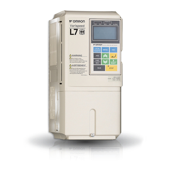
- Page 1 Cat. No. TOEPC71067605-03-OY VARISPEED L7 The frequency inverter for the lifts USER´S MANUAL...
-
Page 2: Table Of Contents
Checking and Controlling the Installation Site ..........1-9 Installation Site ......................1-9 Controlling the Ambient Temperature ................1-9 Protecting the Inverter from Foreign Matter ..............1-9 Installation Orientation and Space .............1-10 Removing and Attaching the Terminal Cover ..........1-11 Removing the Terminal Cover ..................1-11 Attaching the Terminal Cover .................. - Page 3 Wiring Control Circuit Terminals ..............2-17 Wire Sizes ........................2-17 Control Circuit Terminal Functions ................2-18 Control Circuit Terminal Connections ................2-20 EN81-1 Conform Wiring with One Motor Contactor ........2-21 Control Circuit Wiring Precautions ................2-22 Wiring Check ..................... 2-23 Checks ........................2-23 Installing and Wiring Option Cards ............
- Page 4 Lift Function Parameters: S ..................5-47 Motor Autotuning: T ..................... 5-53 Monitor Parameters: U ....................5-55 Settings which change with the Control Mode (A1-02) ..........5-61 Factory Settings Changing with Inverter Capacity (o2-04) .......... 5-63 Parameter Settings by Function ........... 6-1 Carrier Frequency Derating and Current Limitation ..................6-2...
- Page 5 Setting the Ambient Temperature ................6-49 Input Terminal Functions ................6-50 Disable the Inverter Output (Baseblock) ..............6-50 Stopping the Inverter on External Device Errors (External Fault Function) ....6-51 Using the Timer Function .................... 6-52 Motor Contactor Answer Back Detection ..............6-53 Changing the PG direction ..................
- Page 6 Motor torque is insufficient................... 7-20 If the Motor Overheats ....................7-20 If Peripheral Devices are Influenced by the Starting or Running Inverter ....7-21 If the Earth Leakage Breaker Operates When the Inverter is Running ....... 7-21 If There is Mechanical Oscillation ................7-21...
- Page 7 Inverter Application Precautions ............... 10-2 Selection ........................10-2 Installation ........................10-2 Settings ........................10-2 Handling ........................10-3 Motor Application Precautions ..............10-4 Using the Inverter for an Existing Standard Motor ............10-4 Using the Inverter for Special Motors ................10-4 User Constants ..................10-5...
-
Page 8: Warnings
Cables must not be connected or disconnected, nor signal tests carried out, while the power is switched on. The Varispeed L7 DC bus capacitor remains charged even after the power has been switched off. To avoid an electric shock hazard, disconnect the frequency inverter from the mains before carrying out maintenance. -
Page 9: Safety Precautions And Instructions
The DC bus capacitors can remain live for about 5 minutes after the inverter is disconnected from the power. It is therefore necessary to wait for this time before opening its covers. All of the main circuit terminals may still carry dangerous voltages. - Page 10 • During wiring, maintenance or inspection make sure, that the motor is stopped and can not turn. • If the inverter is turned off and the motor must be turned, make sure that motor and inverter output are electrically disconnected.
-
Page 11: Emc Compatibility
Use a power cable with well-grounded shield. Use a shielded motor cable not exceeding 20 meters in length. Arrange all grounds so as to maximize the area of the end of the lead in contact with the ground terminal (e.g. - Page 12 Ground clip Ground plate The grounding surfaces must be highly conductive bare metal. Remove any coats of varnish and paint. –Ground the cable shields at both ends. –Ground the motor of the machine. Installation inverters and EMC filters For an EMC rules compliant installation consider...
-
Page 13: Line Filters
CIMR-L7Z40457 3G3RV-PFI3130-SE 90 x 180 x 366 CIMR-L7Z40557 Maximum Voltage: AC 480V 3phase Ambient Temperature: 45°C (max.) *Permissible emission of power drive systems for commercial and light environment (EN61800-3, A11) (general availability, 1st environment) Inverter Model Line Filter Current Weight... -
Page 14: Registered Trademarks
Registered Trademarks The following registered trademarks are used in this manual. DeviceNet is a registered trademark of the ODVA (Open DeviceNet Vendors Association, Inc.). • InterBus is a registered trademark of Phoenix Contact Co. • Profibus is a registered trademark of Siemens AG. -
Page 16: Handling Inverters
Handling Inverters This chapter describes the checks required upon receiving or installing an Inverter. Varispeed L7 Models ............1-2 Confirmations upon Delivery..........1-3 Exterior and Mounting Dimensions ........1-7 Checking and Controlling the Installation Site ....1-9 Installation Orientation and Space ........1-10 Removing and Attaching the Terminal Cover ....1-11 Removing/Attaching the Digital Operator/ LED Monitor and Front Cover ...............1-13... -
Page 17: Varispeed L7 Models
Varispeed L7 Models es: 200 V and 400 V. The maximum motor capacities The Varispeed L7 Series includes Inverters in two voltage class vary from 3.7 to 55 kW (23 models). Table 1.1 Varispeed L7 Models Specifications Varispeed L7 Maximum (Always specify through the protective structure when ordering.) -
Page 18: Confirmations Upon Delivery
Are any screws or other components Use a screwdriver or other tools to check for tightness. loose? In case of any irregularities in the above items, contact the agency from which the Inverter was purchased or your Omron-Yaskawa Motion Control representative immediately. Nameplate Information The nameplate attached to the side of each Inverter showing the model number, specifications, lot number, serial number and other information about the Inverter. -
Page 19: Inverter Software Version
Fig 1.3 Inverter Specifications Inverter Software Version The inverter software version can be read out from the monitor parameter U1-14. The parameter shows the last for digits of the software number (e.g. display is “2031” for the software version VSL702031). -
Page 20: Component Names
Component Names Inverters of 18.5 kW or Less The external appearance and component names of the Inverter are shown in 1.4. The Inverter with the ter- minal cover removed is shown in 1.5. Mounting holes Front cover Heatsink Digital Operator... - Page 21 Inverters of 22 kW or More The external appearance and component names of the Inverter are shown in 1.6. The Inverter with the ter- minal cover removed is shown in 1.7. Inveter cover Mounting holes Cooling fan Front cover Nameplate...
-
Page 22: Exterior And Mounting Dimensions
10 max. 5 200 V Class Inverters of 22 or 55 kW 200 V/400 V Class Inverters of 3.7 to 18.5 kW 400 V Class Inverters of 22 to 55 kW Fig 1.8 Exterior Diagrams of IP00 Inverters IP20 / NEMA 1 Inverters Exterior diagrams of the IP20/NEMA1 Inverters are shown below. -
Page 24: Checking And Controlling The Installation Site
200 or 400 V Class Inverter with an output of 18.5 kW or less in a panel. Observe the following precautions when mounting the Inverter. Install the Inverter in a clean location which is free from oil mist and dust. It can be installed in a totally •... -
Page 25: Installation Orientation And Space
Fig 1.10 Inverter Installation Orientation and Space 1. The same space is required horizontally and vertically for IP00, IP20 and NEMA 1 Inverters. 2. Always remove the top protection cover after installing an Inverter with an output of 18.5 kW or less in a panel. -
Page 26: Removing And Attaching The Terminal Cover
Inverters of 22 kW or More Loosen the screws on the left and right at the top of the terminal cover, pull out the terminal cover in the direc- tion of arrow 1 and then lift up on the terminal in the direction of arrow 2. -
Page 27: Attaching The Terminal Cover
For Inverters with an output of 18.5 kW or less, insert the tab on the top of the terminal cover into the groove on the Inverter and press in on the bottom of the terminal cover until it clicks into place. -
Page 28: Removing/Attaching The Digital Operator/Led Monitor And
Removing the Digital Operator/LED Monitor Press the lever on the side of the Digital Operator/LED Monitor in the direction of arrow 1 to unlock the Dig- ital Operator/LED Monitor and lift the Digital Operator/LED Monitor in the direction of arrow 2 to remove the Digital Operator/LED Monitor as shown in the following illustration. - Page 29 Removing the Front Cover Press the left and right sides of the front cover in the directions of arrows 1 and lift the bottom of the cover in the direction of arrow 2 to remove the front cover as shown in the following illustration.
-
Page 30: Inverters Of 22 Kw Or More
Digital Operator/LED Monitor is mounted to it. 2. Insert the tab on the top of the front cover into the slot on the Inverter and press in on the cover until it clicks into place on the Inverter. -
Page 32: Wiring
Wiring This chapter describes the terminals, main circuit terminal connections, main circuit terminal wiring specifica- tions, control circuit terminals, and control circuit wiring specifications. Connection Diagram ............2-2 Terminal Block Configuration..........2-4 Wiring Main Circuit Terminals ..........2-5 Wiring Control Circuit Terminals ........2-17 EN81-1 Conform Wiring with One Motor Contactor..2-21... -
Page 33: Connection Diagram
Connection Diagram The connection diagram of the Inverter is shown in 2.1. When using the Digital Operator, the motor can be operated by wiring only the main circuits. DC reactor to improve input Braking Resistor power factor (optional) unit (optional) -
Page 34: Circuit Descriptions
* SELV (Safety Extra Low Voltage) circuits have no direct connection to the primary power and are supplied by a transformer or equivalent isolating device. The circuits are designed and protected, so that, under normal and single fault condition, its voltage does not exceed a safe value. -
Page 35: Terminal Block Configuration
Charge indicator Ground terminal Fig 2.2 Terminal Arrangement (200 V/400 V Class Inverter of 3.7 kW) Control circuit terminals Charge indicator Main circuit terminals Ground terminals Fig 2.3 Terminal Arrangement (200 V/400 V Class Inverter of 22 kW or more) -
Page 36: Wiring Main Circuit Terminals
Applicable Wire Sizes and Crimp Terminals Select the appropriate wires and crimp terminals using Table 2.1 Table 2.3. Refer to instruction manual TOE-C726-2 for wire sizes for Braking Resistor Units and Braking Units. Wire Sizes Table 2.1 200 V Class Wire Sizes Recom- Possible... - Page 37 (3 to 4/0) (1/0) 0.5 to 4 r/l1, Δ/l2 1.3 to 1.4 (20 to 10) (16) *1. The wire size is valid for PVC insulated copper cable, 30° ambient temperature Table 2.2 400 V Class Wire Sizes Recom- Possible Inverter Tightening mended...
- Page 38 W/T3, R1/L11, S1/L21, T1/L31, NO 10 to 16 L7Z4055 4.0 to 5.0 3, PO (8 to 4) 25 to 35 9.0 to 10.0 (4 to 2) *1. The wire size is valid for PVC insulated copper cable, 30° ambient temperature...
- Page 39 1658/12 GS12-95 *1. Not applicable for L7Z2011 Select the wire size for the main circuit so that line voltage drop is within 2% of the rated voltage. Line voltage drop is calculated as follows: IMPORTANT Line voltage drop (V) =...
-
Page 40: Main Circuit Terminal Functions
Main circuit terminal functions are summarized according to terminal symbols in Table 2.4. Wire the terminals correctly for the desired purposes. Table 2.4 Main Circuit Terminal Functions (200 V Class and 400 V Class) Model: CIMR-L7Z Purpose Terminal Symbol 200 V Class... -
Page 41: Main Circuit Configurations
Control Power Control Supply Circuit Supply Circuit CIMR - L7Z2037 to 2055 R/L1 U/T1 S/L2 T/L3 V/T2 R1/L11 W/T3 S1/L21 T1/L31 r/l1 Power Control Δ 200/ l200 Supply Circuit Note: Consult your Omron-Yaskawa Motion Control representative for using 12-phase rectification. -
Page 42: Standard Connection Diagrams
Unit (optional) R/L1 U/T1 S/L2 V/T2 W/T3 T/L3 3 Phase 200VAC or 400VAC R1/L11 S1/L21 T1/L31 r / l1 / l2 Control power is supplied internally from the DC bus at all inverter models. Fig 2.4 Main Circuit Terminal Connections... -
Page 43: Wiring The Main Circuits
Wiring Main Circuit Inputs Consider the following precautions for the main circuit power supply input. Installing Fuses To protect the inverter, it is recommended to use semiconductor fuses like they are shown in the table below. Table 2.6 Input Fuses Rated... - Page 44 Installing an Earth Leakage Breaker An earth leakage breaker which is able to detect all kinds of current should be used in order to ensure a safe earth leakage current detection. If a special-purpose earth leakage breaker for Inverters is used, it should have an actuating current of at •...
- Page 45 Ground Wiring The following precautions should be considered for the ground connection. Always use the ground terminal of the 200 V Inverter with a ground resistance of less than 100 Ω and that • of the 400 V Inverter with a ground resistance of less than 10 Ω.
- Page 46 Connecting a Braking Resistor and Braking Unit (CDBR) A Braking Resistor and Braking Unit can be connected to the Inverter like shown in the 2.7. To prevent overheating of the braking unit/braking resistor, the inverter operation should be stopped when the overload contacts are operated.
- Page 47 2.8. There is a jumper for selecting whether each Braking Unit is to be a master or slave. “Mas- ter” must be set for the first Braking Unit only, “Slave” must be set for all other Braking Units (i.e. from the second Unit onwards).
-
Page 48: Wiring Control Circuit Terminals
For remote operation using analog signals, the control line length between the Analog Operator or operation signals and the Inverter should be less than 30 m. The controller wires should always be separated from main power lines or other control circuits in order to avoid disturbances. -
Page 49: Control Circuit Terminal Functions
*2. Do not use this power supply for supplying any external equipment. *3. When driving a reactive load, such as a relay coil with DC power supply, always insert a flywheel diode as shown in 2.11. Fig 2.11 Flywheel Diode Connection... - Page 50 Sinking/Sourcing Mode (NPN/PNP Selection) The input terminal logic can be switched over between sinking mode (0-V common, NPN) and sourcing mode (+24V common, PNP) by using the jumper CN5. An external power supply is also supported, providing more freedom in signal input methods.
-
Page 51: Control Circuit Terminal Connections
2. If the inverter is mounted separated from the controller cabinet, two physically separated wires for the BB and BB1 terminal should be used in order to keep redundancy in case of a fault of one of the signal lines. -
Page 52: En81-1 Conform Wiring With One Motor Contactor
• drive. The input logic must be PNP. If the elevator safety chain is opened, the inverter output must be cut. This means that the base block sig- • nals at the terminals BB and BB1 must be opened, e.g. via an interposing relay. -
Page 53: Control Circuit Wiring Precautions
T2, W/T3, 2, and 3, PO, NO) and other high-power lines. The wiring for control circuit terminals MA, MB, MC, M1, M2, M3, M4, M5, and M6 (contact outputs) • should be separated from wiring to other control circuit terminals. -
Page 54: Wiring Check
Wiring Check Checks Check all wiring after wiring has been completed. Do not perform continuity check on control circuits. Per- form the following checks on the wiring. Is all wiring correct? • Have no wire clippings, screws, or other foreign material been left? •... -
Page 55: Installing And Wiring Option Cards
Option Card Models and Specifications Up to three option cards can be mounted simultaneously in the Inverter. Each of the three option board sockets on the controller card (A, C and D) can take up one option card like shown in 2.14. -
Page 56: Pg Speed Control Card Terminals And Specifications
Preventing C and D Option Card Connectors from Rising After installing an Option Card into slot C or D, insert an Option Clip to prevent the side with the connector from rising. The Option Clip can be easily removed by holding onto the protruding portion of the Clip and pulling it out. - Page 57 The length of the pulse generator's wiring must not be more than 100 meters. • The direction of rotation of the PG can be set in user parameter F1-05. The factory setting is A-phase • leading in forward direction (motor shaft turning counterclockwise seen from motor shaft side).
- Page 58 Pulse monitor output terminal phase B (–) Pulse monitor output terminal phase Z (+) Pulse monitor output terminal phase Z (–) Common terminal monitor outputs – Shield connection terminal – *1. The 5V and 12V power supply should not be used at the same time.
- Page 59 The length of the pulse generator's wiring must not be more than 100 meters. • The direction of rotation of the PG can be set in user parameter F1-05. The factory setting is A-phase • leading in forward direction (motor shaft turning counterclockwise seen from motor shaft side).
- Page 60 Encoder Power Supply Voltage Selection The encoder power supply voltage must be set according to the encoder type using switch S1 on the PG-F2 card. Using potentiometer RH1 the encoder power supply voltage can be fine adjusted. The switch S1 factory setting is OFF (EnDat is preselected).
- Page 61 ( /DATA) Fig 2.20 PG-F2 Wiring (EnDat signal names in brackets) Precautions: The length of the pulse generator's wiring must not be more than 50m for the signal lines and 30m for • the monitor output at terminal TB3. The direction of rotation of the PG can be set in user parameter F1-05 (PG Rotation). The factory set- •...
-
Page 62: Wiring The Terminal Blocks
Table 2.8). • The signal lines of the PG Speed Control Card should be separated from main power lines and other con- • trol circuits. The shield must be connected (green grounding cable of the option card) to the ground terminal to prevent •... -
Page 64: Led Monitor / Digital Operator And Modes
LED Monitor / Digital Operator and Modes The Varispeed L7 is equipped with the LED Monitor JVOP-163 which shows the drive status. The optional Digi- tal Operator JVOP-160-OY can be used to adjust parameters as required. This chapter describes Digital Operator displays and functions, and provides an overview of operating modes and switching between modes. -
Page 65: Led Monitor Jvop-163
LED Monitor JVOP-163 LED Monitor The LED monitor indicates the operation status by combinations of the LED display (Lights up, Blink, and Off) at RUN, DS1, and DS2. The LED pattern is as follows at each mode. Operation Mode Indicators... -
Page 66: Digital Operator Jvop-160-Oy
Digital Operator JVOP-160-OY Digital Operator Display The key names and functions of the Digital Operator are described below Drive Status Indicators FWD: Lights up when a forward run command is input. REV: Lights up when a reverse run command is input. - Page 67 Note: Except in diagrams, Keys are referred to the key names listed in the above table. There are indicators on the upper left of the RUN and STOP keys on the Digital Operator. These indicators light or flash to indicate the inverter operation status.
-
Page 68: Inverter Modes
Inverter Modes The Inverter's parameters and monitoring functions are organized in five groups which make it easy to read and adjust parameters. The 5 modes and their primary functions are shown in the Table 3.2. Table 3.2 Modes Mode Primary function(s) -
Page 69: Switching Modes
Fig 3.4 Mode Transitions To run the inverter after viewing/changing parameters press the MENU key and the DATA/ENTER key in sequence to enter the Drive mode. A Run command is not accepted as long as the drive is in any other mode. -
Page 70: Drive Mode
U3-04= UV Fig 3.5 Operations in Drive Mode Note: When changing the display with the Increment/Decrement keys, after the last monitor parameter the display jumps back to the first monitor parameter and vice versa (e.g. U1-55 is followed by U1-01). -
Page 71: Quick Programming Mode
The parameters can be changed from the setting displays. Use the Increment, Decrement, and Shift/RESET keys to change the frequency. The parameter is written and the display returns to the monitor display when the DATA/ENTER key is pressed. -
Page 72: Advanced Programming Mode
In the advanced programming mode all Inverter parameters can be monitored and set. A parameter can be changed from the setting displays using the Increment, Decrement, and Shift/RESET keys. The parameter is saved and the display returns to the monitor display when the DATA/ENTER key is pressed. - Page 73 Setting Parameters Here the procedure to change C1-01 (Acceleration Time 1) from 1.5 s to 2.5 s is shown. Table 3.3 Setting Parameters in Advanced Programming Mode Step Digital Operator Display Description -DRIVE- Frequency Ref U1- 01=50.00Hz Power supply turned ON.
-
Page 74: Verify Mode
The parameter A1-02 is the only parameter from the A1- group, which will be displayed in the modified constant list if it has been changed before. The other parameters will not be displayed, even if they are differ- ent from the default setting. -
Page 75: Autotuning Mode
The tuning method for V/f control is fixed to the measurement of the terminal resistance (T1-01=1). Input the the rated output power and the rated current specified on the nameplate of the motor and then press the RUN key. The motor data are measured automatically. -
Page 76: Start Up Procedure
Start Up Procedure This chapter describes the basic setup procedure, the motor data autotuning for each control mode and gives advices if problems occur. General Start Up Routine............4-2 Power Up ................4-3 Autotuning................4-4 Auto Tuning Precautions.............4-5 Autotuning Procedure with Induction Motors ......4-6 Autotuning Procedure with PM Motors .......4-7... -
Page 77: General Start Up Routine
General Start Up Routine Start Up The following chart shows the basic start up sequence. START Mechanical installation Main and control circuit wiring Check the encoder power supply selection * (Closed Loop only) Switch on the power supply Select the control mode in parameter A1-02... -
Page 78: Power Up
-DRIVE- Display for normal operation The Baseblock message blinks. Base Block When a fault has occurred or an alarm is active a fault or alarm message will appear. In this case, refer to Chapter 7, Troubleshooting. -DRIVE- A fault or alarm message is shown on the Display for fault operation display. -
Page 79: Autotuning
1~2 minutes and set the required motor parameters automatically. Use this tuning mode only, if the motor can rotate freely which means that the ropes must be removed and the brake must be open. The gearbox can remain connected to the motor. -
Page 80: Auto Tuning Precautions
This tuning mode is available in Closed Loop Vector control for PM motors only. It automatically sets the off- set between the magnetic pole and the encoder zero postion. It can be used to retune the offset after an encoder change without changing the motor data settings. -
Page 81: Autotuning Procedure With Induction Motors
Autotuning Procedure with Induction Motors Fig 4.2 shows the autotuning procedure for an induction motor with or without encoder in V/f-, Open loop vector and Closed loop vector control. START Set the Base Block Inputs BB and (A1-02 = 2/3) -
Page 82: Autotuning Procedure With Pm Motors
Autotuning Procedure with PM Motors Fig 4.3 shows the autotuning procedure for permanent magnet motors. Before tuning make sure that the con- trol mode is set to PM Closed Loop Vector (A1-02 = 6). START * Remove the ropes so that the motor can rotate freely... -
Page 83: Pm Motor Encoder Offset Tuning
This procedure should be performed if the encoder has been changed or has not been aligned correctly. Before tuning make sure that PM losed loop vector conntrol is selected (A1-02 = 6) and that the E1- and E5- parameters are set up correctly. -
Page 84: Precautions For Induction Motor Autotuning
If speed precision is required at high speeds (i.e., 90% of the rated speed or higher), set T1-03 (Motor rated voltage) to the input power supply voltage × 0.9. In this case at high speeds the output current will increase as the input power supply voltage is reduced. -
Page 85: Autotuning Alarms And Faults
• The inverter calculates the motor power using the input current value and data from the internal motor data table. The calculated value must be between 50% and 150% of the input value for the rated power. -
Page 86: Performance Optimization
Performance Optimization The following table gives adjustment advice for performance improvement after the basic setup has been done. Table 4.3 Performance Optimization Problem Possible Reason Countermeasure • Increase the DC injection current at start in parameter S1-02. • Set the DC injection time at start S1-... - Page 87 • Too fast torque compensation or slip com- delay time C4-02 pensation • Increase the slip compensation delay time C3-02 • Too soft or too hard ASR controller set- • Readjust the ASR P gain C5-01 and Jerk caused by over- tings the ASR integral time C5-02.
-
Page 88: User Parameters
User Parameters This chapter describes all user parameters that can be set in the Inverter. User Parameter Descriptions..........5-2 Digital Operation Display Functions and Levels ....5-3 User Parameter Tables............5-8 Setup Settings: A ..............5-8 Application Parameters: b..........5-10 Tuning Parameters: C............5-12 Reference Parameters: d..........5-18 Motor Parameters: E............5-21... -
Page 89: User Parameter Descriptions
User Parameter Descriptions Description of User Parameter Tables User parameter tables are structured as shown below. Here, b1-01 (Frequency Reference Selection) is used as an example. Control Methods Name Param- Change MEMO- Closed eter Setting Factory during Open Closed Description... -
Page 90: Digital Operation Display Functions And Levels
Digital Operation Display Functions and Levels The following figure shows the Digital Operator display hierarchy for the Inverter. Function Page 5-55 Status Monitor Parameters Fault Trace 5-59 MENU Drive Mode Fault History 5-60 Initialize Mode Inverter can be operated and its status can be displayed. -
Page 91: User Parameters Available In Quick Programming Mode
The minimum user parameters required for Inverter operation can be monitored and set in quick programming mode. The user parameters displayed in quick programming mode are listed in the following table. These, and all other user parameters, are also displayed in advanced programming mode. - Page 92 ASR proportional 20.00 (P) gain 2 0.00 to C5-03 21DH 300.00 Set the proportional gain 2 and the inte- ASR P Gain 2 6.00 gral time 2 of the speed control loop ASR integral (I) (ASR) for the maximum frequency. 0.000...
- Page 93 0.0 V (VBASE) 510.0 E1-13 30CH Base Voltage 400 V Motor rated current Sets the motor rated current in Amps. 0.85 to This set value becomes the base value 7.00 A 17.00 E2-01 30EH for motor protection and torque limit. It Mtr Rated Current is an input data for autotuning.
- Page 94 *2. The given values are for a 400 V class Inverter. *3. The setting range is from 10% to 200% of the Inverter rated output current. The given values are for a 3.7 kW 400 V Class Inverter. *4. The factory setting depends on the Inverter capacity. The given value is for a 3.7 kW 400 V Class Inverter.
-
Page 95: User Parameter Tables
6-70 A1-01 0 to 2 101H (Only parameters set in A2-01 6-71 to A2-32 can be read and set.) 2: Advanced (Parameters can be read and set Access Level in both, quick programming mode (Q) and advanced pro- gramming mode (A).) - Page 96 9999 RESET key and press the Menu Select Pass- key. The password will be dis- word played. User-set Parameters: A2 The parameters set by the user are listed in the following table. Control Methods Name Param- Change MEMO- Closed eter...
-
Page 97: Application Parameters: B
Page Loop Num- Range Setting Opera- Display Loop Loop Register Vector tion Vector Vector (PM) Magnetic flux compensation Sets the magnetic flux compensa- 0 to volume b2-08 tion as a percentage of the no- 190H 1000 load current. Field Comp... - Page 98 Loop Register Vector Display tion Vector Vector (PM) Sets the timer function output ON- Timer function delay time (dead band) for the timer ON-delay time 0.0 to b4-01 function input, in 1-second units. 0.0 s 1A3H 6-52 300.0 Delay-ON Enabled when a timer function is set...
-
Page 99: Tuning Parameters: C
Acc/Dec SW Freq 0.0 % the set frequency: Accel/decel 100.0 time 1. *1. The setting range for acceleration/deceleration times depends on the setting of C1-10. If C1-10 is set to 1, the setting range for acceleration/deceleration times becomes 0.0 to 6000.0 seconds. - Page 100 2.50 S-Crv Acc @ Start S-curve char- Set the S-curve times at speed changes acteristic time to reduce the jerk. The S-curves can be 0.00 at accelera- set separately for every kind of speed C2-02 0.50 s 20CH...
- Page 101 Usually changing this setting is not Slip compen- necessary. sation gain Adjust this parameter under the fol- lowing circumstances. • When motor speed is lower than the frequency reference increase 0.0 to C3-01 20FH 6-29 the set value.
- Page 102 REV direction to 0.0 RTorqCmp @ Start Starting torque compensation Sets starting torque start-up time constant time. C4-05 0 to 200 10 ms 219H 6-30 When 0 ~ 4 ms is set, it is oper- ated without filter. TorqCmpDelayT...
- Page 103 C5-02 21CH 6-32 10.000 ASR I Time 1 0.300 ASR propor- 20.00 tional (P) gain 2 Set the proportional gain 2 and the 0.00 to C5-03 21DH 6-32 integral time 2 of the speed control 300.00 ASR P Gain 2 loop (ASR) for the minimum fre- 3.00...
- Page 104 Loop Loop Range Setting Register Display Vector tion Vector Vector (PM) Selects the carrier frequency for PM Carrier fre- motor control modes quency selec- 1: 2 kHz tion 2 2: 4 kHz C6-11 1 to 6 22DH 3: 6 kHz...
-
Page 105: Reference Parameters: D
120.00 0.00 0.00 0.00 Sets the frequency reference ence 4 *1,*2 when multi-step speed com- d1-04 283H mands 1 and 2 are ON for multi- 0 to function inputs. Reference 4 100.00 0.00 % 0 to Frequency refer- 120.00 0.00 0.00... - Page 106 Spd@Door Motor *1. The unit is set in o1-03 (frequency units of reference setting and monitor, default: 0.01 Hz). If the display unit is changed, the setting range values also change *2. The maximum setting value depends on the setting of the maximum output frequency (E1-04).
- Page 107 Sets the upper limit for the excitation ing function current applied by the field forcing Limit function. 100 to d6-06 A setting of 100% is equal to the 400% 2A5H 6-38 motor no-load current. FieldForce Field forcing is active during all types Limit of operation except DC Injection.
-
Page 108: Motor Parameters: E
Sets the output voltage of the base fre- (VBASE) 510.0 E1-13 30CH 6-59 quency (E1-06). 0.0 V 0.0V 200 V Base Voltage *1. The given values are for a 400 V Class Inverter. *2. E1-13 is set to the same value as E1-05 by autotuning. - Page 109 310H 6-59 No-Load during autotuning. Current Number of Sets the number of motor poles. motor poles E2-04 This value is an input data for autotun- 2 to 48 4 poles 311H 6-59 Number of ing. Poles Motor line- Sets the motor phase-to-phase resis- to-line resis- 0.000...
- Page 110 *2. The factory setting depends upon the Inverter capacity. The given value is for a 400 V inverter with 3.7 kW. *3. The setting range depends on the inverter capacity and on the setting of E2-01. The maximum value is E2-01 minus 0.01A. The given setting range is for a 400 V inverter with 3.7 kW.
- Page 111 *2. The factory setting depends upon the Inverter capacity. The given value is for a 400 V inverter with 3.7 kW. *3. The setting range depends on the inverter capacity and on the setting of E2-01. The maximum value is E2-01 minus 0.01A. The given setting range is for a...
- Page 112 *1. The factory setting depends upon the Inverter capacity. The given value is for a 400V class inverter with 3.7 kW. *2. The setting range is 10% to 200% of the Inverter's rated output current. The given value is for a 400 V class inverter of 3.7 kW is given.
-
Page 113: Option Parameters: F
(PG pulse mon- Division ratio = (1+ n) /m itor) (n=0 or 1 m=1 to 32) The first digit of the value of F1-06 F1-06 stands for n, the second and the 1 to 132 385H 6-73 third stands for m. - Page 114 0 to PG Input Pulses x 60 F1-13 1000 Number of PG F1-01 F1-12 gear teeth 2 A gear ratio of 1 will be used if one F1-13 38CH 6-73 PG#Gear of these parameters is set to 0. Teeth2 PG open-cir-...
- Page 115 Sets wether saving parameters in write permis- the encoder is permitted or not. sion selection F1-26 0 or 1 3B5H 6-75 0: Write prohibited Write Allow- 1: Write permitted able *1. Can be set only if HIPEFACE is selected as encoder type.
- Page 116 394H 6-25 1000.0 AO Ch2 Gain (Numerical portion of U1- Channel 1 output -110.0 4, 10, 11, 12, 13, 14, 25, 28, 34, monitor bias F4-05 0.0% 395H 6-25 35, 39 and 40 cannot be set. 110.0 AO Ch1 Bias...
- Page 117 Digital Output Card (DO-02 and DO-08): F5 Name Control Methods Change MEMO Con- Fac- Closed Setting during Open Closed stant Description tory Page Loop Range Opera- Regis- Display Loop Loop Number Setting Vector tion Vector Vector (PM) Channel 1 output...
- Page 118 Vector Vector (PM) Sets the stopping method for Operation selection communications errors. after communica- 0: Deceleration to stop using the tions error deceleration time in C1-02 F6-01 0 to 3 3A2H 1: Coast to stop 2: Emergency stop using the...
-
Page 119: Terminal Function Parameters: H
6-62 Emergency stop (NC: Deceleration to stop in deceleration time set in C1-09 when OFF) 6-10 Timer function input (the times are set in b4-01 and b4-02 and the timer function output is set 6-52 in H2- Accel/decel time switch over 2 6-21 20 to 2F External fault;... - Page 120 6-56 agree 1 (detection width L4-02 is used.) 6-26 agree 1 (ON: Output frequency = ±L4-01, with detection width L4-02 used and dur- 6-26 ing frequency agree) Frequency detection 1 (ON: +L4-01 ≥ output frequency ≥ -L4-01, with detection width L4-...
- Page 121 Not Zero Speed 6-58 Light load direction output (ON: Forward, OFF: Reverse) 6-80 Light load detection status (ON: Ready for light load test, OFF: Light load test in progress) 6-80 Hardware base block monitor 1 (ON: terminal BB and BB1 closed) 6-58...
- Page 122 0: 0 to +10V AI-14 CH1 LvlSel 1: -10 to +10V AI-14B Channel 1 Sets the frequency reference H3-02 gain value when 10 V is input as a per- 0.0 to 100.0% 411H 6-25 1000.0 centage of the maximum output AI-14 CH1 Gain frequency set in E1-04.
- Page 123 0.0% 436H 6-25 centage of the maximum fre- +100.0 Terminal A1 Bias quency set in E1-04. *1. This parameter is available only if an analog input option board AI-14B is installed. H3-05,H3-09 Settings Control Methods Open Closed Setting Closed Function...
-
Page 124: Protection Function Parameters: L
DC bus 0 to Sets the DC bus voltage during L2-11 Voltage 0 VDC 4CBH 6-77 rescue operation. Volt@batterydr *1. These are values for a 200 V class Inverter. The value for a 400 V class Inverter is the double. - Page 125 Register Vector Display tion Vector Vector (PM) 0: Disabled (Acceleration as set. With a too heavy load, the motor Stall prevention may stall.) selection dur- 1: Enabled (Acceleration stopped ing accel when L3-02 level is exceeded. Acceleration starts again when...
- Page 126 1: Output (Fault contact is acti- vated.) Selects the reset method for a Under voltage fault UV1 fault. restart selection 0: UV1 fault is reset like set in L5-05 0 or 1 4CCH 6-81 parameter L5-01 1: UV1 fault is always automat- UV1 Restart Sel.
- Page 127 Torq Det 1 Time Torque detection selection 2 L6-04 0 to 8 4A4H 6-40 Torq Det 2 Sel Torque detection See L6-01 to L6-03 for a descrip- level 2 0 to L6-05 150% 4A5H 6-40 tion. Torq Det 2 Lvl Torque detection 0.0 to...
- Page 128 Forward drive 0 to torque limit L7-01 300% 4A7H 6-43 Sets the torque limit value as a per- Torq Limit Fwd centage of the motor rated torque. Reverse drive Four individual regions can be set. 0 to torque limit L7-02...
- Page 129 Sets the detection time of out- 0.0 to L8-20 0.2sec 4C0H 6-48 put phase loss detection (LF.) Pha loss det T *1. The factory setting depends upon the Inverter capacity. The value for a 200 V Class Inverter of 3.7 kW is given.
-
Page 130: Special Adjustments: N2 / N5
6-34 10.00 set value. • If response is low, decrease the set value. AFR Gain Adjust the setting by 0.05 at a time, while checking the response. Speed feedback detection control Set the time constant 1 to decide 0 to... -
Page 131: Pm Motor Adjustments: N8 / N9
N5-02 Tuning 1: Enabled *1. The factory setting depends on the inverter capacity. The value for a 200 V Class Inverter of 3.7 kW is given.Automatic Frequency Regulator: n2 PM Motor Adjustments: n8 / n9 PM Motor Adjustment 1: n8... -
Page 132: Digital Operator/Led Monitor Parameters: O
6-64 2: Output frequency Power-On Moni- 3: Output current 4: The monitor item set for o1- Sets the units that will be set and displayed for the frequency ref- erence and frequency monitor. 0: 0:0.01 Hz units Frequency units 1: 0.01% units (Maximum out-... - Page 133 Local/Remote parameter settings b1-01, b1-02.) Enables/Disables the Stop key in STOP key during the run mode. control circuit ter- 0: Disabled (When the run com- minal operation mand is issued from an exter- o2-02 0 or 1 506H 6-65 nal terminal, the Stop key is disabled.)
-
Page 134: Lift Function Parameters: S
Inverter 682H 6-39 at stop rated current. DC Inj I @stop DC injection Used to set the time to perform DC braking/ Zero injection braking at start in units of speed time at 1 second. 0.00 S1-04... - Page 135 Register Display Vector tion Vector Vector (PM) DC injection Used to set the time to perform DC braking/ Zero injection braking at stop in units of speed time at 1 second. 0.00 S1-05 stop Used to prevent coasting after the 0.60 s...
- Page 136 16383 the range (the zero-servo position + zero-servo completion width.) Zero Servo Set S1-21 to 4 times of the allow- Count able displacement pulse amount at the PG. Starting torque Sets the increase time for the ana-...
- Page 137 1000 S1-30 0~5000 69DH 6-15 msec The set value is the time used to Torq Fadeout- decrease the compensation value Time from 300% to 0%. Torque limit Sets the time which is used to time at stop...
- Page 138 S3-10 3.00 Hz 6C6H 6-77 20.00 rescue operation. LightLd Srch- Freq Rescue opera- tion torque limit Sets the torque limit for the rescue S3-11 0 to 300 100 % 6C7H 6-77 operation. Rescue OP Base Block Sets the behaviour of the inverter...
- Page 139 Opera- Loop Loop Register Display Vector tion Vector Vector (PM) Roping Sets the roping ratio of the eleva- S3-14 1 or 2 6CAH 6-65 1: 1:1 Roping Ratio 2: 1:2 Gear Ratio 0.10 to S3-15 Sets the mechanical gear ratio.
-
Page 140: Motor Autotuning: T
*2. These are values for a 200 V class Inverter. Values for a 400 V class Inverter are double. *3. The setting range is from 10% to 200% of the Inverter rated output current. (The value for a 200 V Class Inverter for 0.4 kW is given.) - Page 141 VoltConst- T2-08 CalcSel 1: Automatic calculation *1. The factory setting depends on the Inverter capacity. (The value for a 200 V Class Inverter for 3.7 kW is given.) *2. Can be set only if HIPEFACE is selected as encoder type.
-
Page 142: Monitor Parameters: U
U1-09 reference value for open vec- 0.1% Torque (0 to ± 10 V possible) tor control. Reference *1. The unit is set in o1-03 (frequency units of reference setting and monitor) Control Methods Name Param- MEMO- Closed eter Output Signal Level During Min. - Page 143 Inverter. operation time The initial value and the operat- U1-13 (Cannot be output.) ing time/power ON time selec- tion can be set in o2-07 and o2- Elapsed Time Software No. (flash memory) U1-14 (Manufacturer’s ID number) (Cannot be output.)
- Page 144 This frequency value does not 10 V: Max. frequency U1-20 include compensations, such as (0 to ± 10 V possible) slip compensation. SFS Output 0.01% The unit is set in o1-03. Monitors the input to the speed ASR input control loop.
- Page 145 Iq Reference d-axis motor current refer- Monitors the d-axis current ref- 10 V: Motor rated current U1-75 0.1% 7C7H ence erence. (-10 to 10 V) Id Reference *1. The parameter is displayed only if a AI-14B option board is installed.
- Page 146 Inverter Status Cumulative opera- The operating time when the last tion time at fault U2-14 (Cannot be output.) fault occurred. Elapsed Time The following errors are not recorded in the error log: CPF00, 01, 02, 03, UV1, and UV2. IMPORTANT...
- Page 147 U3-15 Total generating time when 5th...10th previous 810H – 811H fault occurred U3-20 Elapsed Time 5 to 10 812H 813H The following errors are not recorded in the error log: CPF00, 01, 02, 03, UV1, and UV2. IMPORTANT...
-
Page 148: Settings Which Change With The Control Mode (A1-02)
0 to 39999 o1-04 V/f pattern frequency parameter unit 0 or 1 S1-01 Zero speed level 0.00 to 10.00 *1. The given values are for a 400 V class Inverter. *2. Can be set only if Hiperface is selected as interface. - Page 149 12.5 E1-09 E1-10 11.0 13.0 E1-13 200.0 *1. The settings shown are for 200 V class Inverters. The values will double for 400 V class Inverters. 200 V and 400V Class Inverters of 55 kW* Para meter Open Closed Closed...
-
Page 150: Factory Settings Changing With Inverter Capacity (O2-04)
Factory Settings Changing with Inverter Capacity (o2-04) 200 V Class Inverters Parameter Name Unit Factory Setting Number Inverter Capacity 18.5 o2-04 kVA selection C6-02 Carrier frequency E2-01 (E4-01) Motor rated current 14.00 19.60 26.60 39.7 53.0 65.8 77.2 E2-02 (E4-02) Motor rated slip 2.73... - Page 151 1.152 0.922 0.550 (E4-05) E2-06 Motor leak inductance 19.3 19.3 18.2 15.5 19.6 17.2 (E4-06) Motor iron loss for torque compen- E2-10 sation E5-02 PM motor rated power 3.70 4.00 5.50 7.50 11.0 15.0 E5-03 PM motor rated current 7.31 7.31...
-
Page 152: Parameter Settings By Function
Parameter Settings by Function Carrier Frequency Derating and Current Limitation ....6-2 Control / Brake Sequence...........6-3 Acceleration and Deceleration Characteristics ....6-20 Adjusting Analog Input Signals .........6-25 Speed Detection and Speed Limitation......6-26 Improving the Operation Performance......6-29 Protective Functions ............6-40 Inverter Protection.............6-47 Input Terminal Functions ..........6-50 Output Terminal Functions..........6-56... -
Page 153: Carrier Frequency Derating And Current Limitation
Carrier Frequency Selection The factory setting is 8 kHz for units from 3.7 to 22 kW and 5 kHz for units from 30 to 55 kW. Usually the value has not to be changed. However, if it necessary to change it, observe the following precautions: If speed and torque oscillate at low speeds: Lower the carrier frequency. -
Page 154: Control / Brake Sequence
When a digital input is set as contactor confirmation input, the contactor confirmation signal must be • present before the travel starts. To start in the Up direction the Up signal must be set. To start in the Down direction the Down signal must • be set. -
Page 155: Speed Reference Source Selection
Input the Speed Reference Using a Voltage Signal (b1-01=1) When b1-01 is set to 1 the speed reference can be input at terminal A1 as a 0 to +10V signal. If an analog option card AI-14B is installed, the A1 signal is replaced by the Channel 1 input of the AI card. -
Page 156: Speed Selection Sequence Using Digital Inputs
Speed Selection Sequence Using Digital Inputs If the digital inputs are used for speed selection, the speed selection method and the speed priority depends on the setting of parameter d1-18. Control Methods Change Closed Parameter Factory Open Closed Name during... - Page 157 The following table shows the combinations of the digital input and the according speed. If b1-02 is set to “1”, speed 1 is input as analog reference at terminal A1 or Channel CH1 of an analog input option card AI-14B if it is installed.
- Page 158 (d1-17) when the selected speed signal is removed. Inspection Speed can not be selected as travel speed. The higher speed has priority over the leveling speed, i.e. as long as a higher speed is selected, the leveling signal is disregarded (see the fig. below) The inverter stops when the leveling signal or the Up/Down signal is removed.
- Page 159 Higher Speed Priority is Selected and a Leveling Speed Input is Not Selected (H1- K83) When the leveling speed command is not selected for any digital input, the inverter decelerates to the leveling speed (d1-17) when the selected speed signal is removed. Inspection Speed can not be selected as travel speed To select the leveling speed as travel speed the frequency reference loss detection must be disabled (S3-09=0).
- Page 160 K80)) If d1-18 is set to “2” and no digital input is set to nominal speed selection, the speed reference with speed selection input set is nominal speed (d1-09). When the leveling speed signal is set, the inverter starts to decel- erate to the leveling speed.
-
Page 161: Emergency Stop
) is set to 15 or 17 (emergency stop), this input can be used to fast stop the inverter in the case of emergency. In this case the emergency stop deceleration time set in C1-09 is used. If the emergency stop is input with an NO contact, set the multi-function input terminal (H1-... -
Page 162: Inspection Run
The inspection run can be activated in two ways: 1. A digital input can be used if parameter d1-18 = 1 or 2. Therefore a inspection speed must be set and any of the digital inputs must be set to “Inspection Run Selection” (H1- =84) (see below). - Page 163 Brake opened (D/O) S3-03 > 0 sec., Stop with deceleration ramp The inverter stops when the Inspection Speed command or the Up/Down command is removed. In this case: The output frequency is reduced using the deceleration time set in S3-03.
-
Page 164: Brake Sequence
Brake Sequence The L7 supports two types of brake sequences, one with torque compensation at start using an analog input value and one without torque compensation at start. Related Parameters Control Method Change Parameter Factory Open Closed Closed Name during... - Page 165 * the time S1-04 – S1-06 has elapsed if S1-06 < S1-04 or * the time S1-06 has elapsed if S1-06 > S1-04 (try to avoid this setting since the motor could be driven against the brake) The speed is increased to the selected speed and is kept constant until the leveling speed is selected.
- Page 166 The torque compensation input source can be selected as follows: the analog input A1 can be used, if b1-01 is not set to 1 (speed reference source is not the A1 input) and the • A1 function is selected for torque compensation (H3-15=1) the channel Ch1 of an AI-14B option card can be used, if b1-01 is not set to 1 (speed reference source is •...
- Page 167 S1-22. The speed is decreased to the leveling speed and is kept constant until the stop signal is given (depending on d1-18 either by removing the direction signal, by removing the leveling signal or by deleting the speed inputs, see...
-
Page 168: Short Floor Operation
40% speed and keeps it for a calculated time before it decelerates to the leveling speed. If the leveling input is set during constant speed run and the speed reference is lower than 40% of the nom- inal speed, the speed is hold for a calculated time in order to minimize the leveling distance. If the speed reference is higher than 40% but lower than the nominal speed, the speed is decreased to t 40% first, is hold for a calculated time an then decreased to the leveling speed. - Page 169 The short floor function can be activated by setting parameter S3-01 to 1. • If parameter d1-18 is set to 0 or 3 (multispeed input), the set value of parameter S3-05 is taken as nominal • speed reference for the short floor calculation. Additionally it is required to use the nominal/leveling speed...
- Page 170 S3-21 and S3-22. 2. A too low gain setting can result in a too high optimal speed and too short leveling time. Very low settings can lead to an overrun. Do not set the values lower than 100% (100% means, that the S- IMPORTANT curve is not compensated.
-
Page 171: Acceleration And Deceleration Characteristics
Setting Acceleration and Deceleration Times The acceleration time indicates the time to increase the speed from 0% to 100% of the maximum speed set in E1-04. The deceleration time indicates the time to decrease the speed from 100% to 0% of E1-04. - Page 172 Fig 6.5 Dwell at start function Note: When C1-11 is set much higher than S1-26, the motor speed cannot reach C1-11 and the motor can not accelerate to the selected speed. Therefore always set C1-11 equal or lower than S1-26!
-
Page 173: Acceleration And S-Curve Settings
Acceleration and S-curve Settings Five different S-curve times are used to reduce the jerk when the speed changes. Related Parameters Control Methods Change Closed Parameter Factory during Open Closed Name Loop Setting Opera- Loop Loop Vector tion Vector Vector (PM) -
Page 174: Stall Prevention During Acceleration
When L3-02 is exceeded, the acceleration will stop. If L3-01 is set to 2 (optimal adjustment), the motor accelerates so that the current is held at the level set in L3- 02. With this setting, the acceleration time setting is ignored. - Page 175 If the motor stalls with the factory settings check the V/f pattern settings (E1- ) and the motor setup • (E2- If the stall level has to be increased very much to get the elevator running, consider to use a one size bigger • inverter.
-
Page 176: Adjusting Analog Input Signals
The frequency reference can be input from the control circuit terminals using analog voltage. The voltage level at terminal A1 is 0 to +10V. The analog input channels of the AI-14B option card can be used with 0 to +10V or -10 to +10V. -
Page 177: Speed Detection And Speed Limitation
With L4-01 an absolute speed agreement level is set, i.e. a speed agreement is detected in both directions • (Up and Down). With L4-03 a signed speed agreement level is set, i.e. a speed agreement is detected only in the set direc- • tion (positive level → Up direction, negative level → Down direction). - Page 178 Time Charts The following table shows the time charts for each of the speed agreement functions. Related L4-01: Speed Agree Level L4-03: Speed Agree Level +/– parameter L4-02: Speed Agree Width L4-04: Speed Agree Width Agree 2 Agree 1 Frequency...
-
Page 179: Limiting The Elevator Speed To The Leveling Speed (D1-17)
Limiting the Elevator Speed to the Leveling Speed (d1-17) To use a high speed limit in the UP or DOWN direction to the leveling speed, one of the digital inputs must be set to “High speed limit switch Up” or “High speed limit Down” (H1- = 87/88). -
Page 180: Improving The Operation Performance
Output voltage limit operation selection Adjusting Slip Compensation Gain (C3-01) If C3-01 is set to 1.0, the slip compensation value at 100% load is equal to the rated slip set in parameter E2-02. If necessary (motor speed is too high or too low) adjust the slip compensation gain as follows: 1. -
Page 181: Torque Compensation Function Adjustments
100%. If the speed is lower than the target value but does not change even after adjusting the slip compensation gain, the slip compensation limit may have been reached. Increase the limit, and check the speed again. Always make sure that the value of the slip compensation limit and reference frequency does not exceed the tolerance of the machine. - Page 182 Torque compensation delay time constant 2000 ms Adjusting Torque Compensation Gain (C4-01) Normally, there is no need to change this setting. If adjustments are necessary do the following: Open Loop Vector control If the torque response is slow increase the set value.
-
Page 183: Starting Torque Compensation Function (C4-03 To C4-05)
Starting Torque Compensation Function (C4-03 to C4-05) A starting torque compensation can be applied to speed up the torque establishment at start in Open Loop Vec- tor control. Related Parameters Control Methods Change Closed Parameter Factory Open Closed Name during... - Page 184 During Deceleration When the ride starts with the nominal speed selected, the ASR P gain and I time change from C5-03/04 to C1- 01/02 at nominal speed. When the speed selection changes to leveling speed, the P gain and I time are changed from C1-01/02 to C1-09/10.
-
Page 185: Stabilizing Speed (Automatic Frequency Regulator) (Open Loop Vector)
Increase C5-09 if ASR is slow in the low speed area or if undershooting occurs at leveling speed. If vibra- • tions occur in the low speed area during deceleration decrease the value. Adjusting ASR Integral Times (C5-02/04/10) The integral time determines how fast the ASR input is integrated in order to eliminate the speed deviation. -
Page 186: Inertia Compensation (Closed Loop Vector Only)
The motor acceleration time n5-02 can be calculated by an auto tuning function. It sets the internal accelera- tion time to 0.1 sec., disabled the S-curve and sets the torque limit to 100%. After that a start in each direction must be performed. -
Page 187: Automatic Current Regulator (Acr) Tuning
3. Enable the inspection speed input. “FFCAL” will blink in the display to signalize that the calculation is active. 4. Set an UP command. The inverter will accelerate the motor up to the nominal speed. Release the UP com- mand a few seconds after the top speed has been reached. -
Page 188: A/D Conversion Delay Time Tuning
The inverter measures the current level or torque reference S2-05 sec. after the speed-agree condition (acceler- ation finished) for the time set in S2-06 and calculates the average value to estimate the load. This value is used for the calculation of slip which is added to the speed reference at leveling speed (see 6.14). -
Page 189: Field Forcing
Thereby it improves the motor responsiveness to changes in the speed reference or the load. Field forcing is applied during all operation conditions except DC Injection. Using parameter d6-06 a field forcing limit can be applied. A setting of 100% is equal to the no-load current set in parameter E2-03. -
Page 190: Adjusting The Dc Injection Current
Adjusting the DC Injection Current The DC current injection is used in V/f and Open Loop Vector Control in order to hold the motor when the brake is opened or closed. Related Parameters Control Methods Change Closed Parameter Factory Open... -
Page 191: Protective Functions
L3-05. Set the according deceleration times using C1-02 (Deceleration time 1) or C1-04 (Deceleration Time 2). If the Inverter output current reaches the set value in L3-06 – 2%, the motor will accelerate again to the set fre- quency. - Page 192 (NC contact: Overtorque detection and undertorque detection enabled when contact is OFF) L6-01 and L6-04 Set Values and Operator Display (JVOP-160-OY only) The relationship between alarms displayed on the digital operator when overtorque or undertorque is detected, and the set values in L6-01 and L6-04, is shown in the following table.
- Page 193 (output is switched) when the torque/current is higher than 150% for 10 sec. The level can be adjusted in L6-02, the time in L6-03. The output is switched of and an OL3 fault will be indicated (see 6.17)
-
Page 194: Limiting The Motor Torque (Torque Limit Function)
This function allows limitation of motor shaft torque independently for each of the four quadrants. The torque limit can be set as a fixed value using parameters or as a variable value using an analog input. The torque limit function can be used with Open Loop Vector and Closed Loop Vector control only. -
Page 195: Motor Overload Protection
L1-01 Motor protection selection L1-02 Motor protection time constant 1.0 min *1. Factory settings depend on Inverter capacity. (The given value is for a 400 V Class Inverter with 3.7 kW.) Multi-Function Outputs (H2-01 to H2-03) Control Methods Closed Open... - Page 196 Setting a Motor Overload Pre-Alarm If the motor overload protection function is enabled (i.e., L1-01 is set to a value different from 0) and H2-01 to H2-03 (output terminals M1-M2, M3-M4, and M5-M6 function selection) to 1F (motor overload OL1 pre- alarm), the motor overload pre-alarm will be output at the selected terminals.
-
Page 197: Output Current Observation
SE2 fault (SE2, Current observation at start) The current is measured for the time S1-06 + S1-14 (Brake open delay plus SE2 detection time) after the Up/ Down command input. If it is/falls below 25% of the motor no-load current (E2-03) a SE2 fault is output. -
Page 198: Inverter Protection
When the overheat temperature level is reached the inverter output is switched off. To prevent a sudden and unexpected stop of the inverter due to an over temperature, an overheat pre-alarm can be output. The temperature level for that pre-alarm can be set in parameter L8-02. Using parameter L8-03 the inverter operation when an over temperature occurs can be selected. -
Page 199: Output Open Phase Detection
This function detects the earth leakage current by calculating the sum of the three output currents. Normally it should be 0. If the earth leakage current gets too high, the inverter output is switched off and a GF fault is shown on the display. -
Page 200: Cooling Fan Control
Using parameter L8-10 two modes can be selected: 0: The fan is ON only when the inverter output is ON, i.e. a voltage is output. This is the factory setting. The turn OFF delay time for the fan can be set in parameter L8-11. After a stop command the inverter waits for this time before switching OFF the cooling fan. -
Page 201: Input Terminal Functions
When hardware baseblock is activated, the power supply of the IGBT driver circuit is cut off and the motor starts to coast. To use this baseblock function the digital input S8 must be used. The input is a NC input, i.e. if terminal S8 is open, the inverter is base block condition. -
Page 202: Stopping The Inverter On External Device Errors (External Fault Function)
For example, if an external fault signal is input to terminal S3, EF3 will be displayed. To use the external fault function, set one of the values 20 to 2F in one of the parameters H1-01 to H1-05 (dig- ital input terminal S3 to S7 function selection). -
Page 203: Using The Timer Function
(Warning) * 1. Sets the input level at which errors are detected. (NO contact: External error when ON; NC contact: External error when OFF). * 2. Set the detection method to detect errors using either constant detection or detection during operation. -
Page 204: Motor Contactor Answer Back Detection
Setting Example When the timer function input is ON for longer than b4-01, the timer output function is turned ON. When the timer function input is OFF for longer than b4-02, the timer output function is turned OFF. An example of timer function operation is given in the following diagram. -
Page 205: Changing The Pg Direction
Case 4 Changing the PG direction A digital input can be used to change over the PG feedback signal direction. Therefore one of the parameters must be set to 89. The PG direction is clockwise (CW) when the input is open and counterclockwise (CCW) when the input is closed. -
Page 206: Motor 2 Selection
(H2- = 1C). If motor 2 is selected, the speed set in d1-19 will be the speed reference. d1-19 has priority over all speed inputs except the service speed input. The output signal sequence (brake control, contactor etc.) is the same as for motor 1. -
Page 207: Output Terminal Functions
The output frequency is lower than the zero speed level*. * The Zero Speed Level depends on the control mode. It is 0.1 Hz for Closed Loop Vector, 0.5 Hz for Open Loop Vector and 1.2 Hz for V/f control. - Page 208 During DC Bus Undervoltage (Setting: 7) If a multifunction output is set to this function, the output is switched ON as long as a DC bus under voltage is detected. During Baseblock (Setting: 8) If a multifunction output is set to this function, the output is switched ON as long as the inverter output is base blocked.
- Page 209 6-16, Zero Speed Control / Zero Servo (position lock). Brake Release Command (Setting: 40) This output signal can be used to control the brake. The output is closed when the brake shall be opened. Refer also to page 6-13, Brake Sequence.
-
Page 210: Motor And V/F Pattern Setup
The L7 inverter supports 2 motor settings (main motor and door motor, E2/E4- parameters) for V/f con- trol, Open Loop Vector and Closed Loop Vector for IM. The active motor setup can be selected by a digital input. Closed Loop Vector Control for PM supports 1 motor setting (main motor, E5- parameters) only. - Page 211 *2. The value depends on the control mode. The given value is valid if V/f control is selected. *3. All factory-set parameters are for a Yaskawa standard 4-pole motor. The factory settings depend on Inverter capacity (the values shown are for a 400 V Class Inverter for 3.7 kW). *4. Rotating tuning only...
- Page 212 Output voltage (V) Frequency (Hz) Fig 6.24 V/f pattern setting To set the V/f characteristics linear, set E1-07 and E1-09 to the same value. In this case, E1-08 will be ignored. INFO Setting Precautions When a user-defined V/f pattern is used, consider the following points: By changing the control method, the parameters E1-07 to E1-10 are changed to the factory settings for the •...
-
Page 213: Setting Motor Parameters For Pm Motors
Motor q-axis inductance 26.08 mH E5-09 Motor voltage constant 478.6 mV *1. The given value is valid for 400V inverters. *2. The factory settings depend on Inverter capacity (the values shown are for a 400 V Class Inverter for 3.7 kW). -
Page 214: Motor Rotation Direction Change
Motor Rotation Direction Change If the motor operates in the wrong direction with an Up or Down command, the direction can be changed by parameter S3-08. -
Page 215: Digital Operator/Led Monitor Functions
*1. Depends on the inverter capacity Monitor Selection (o1-01) Using parameter o1-01 the third monitor item that is displayed in drive mode can be selected. This function has no effect on the LCD-operator (JVOP-160-OY). Monitor Display when the Power Supply is Turned ON (o1-02) - Page 216 This parameter is used to set if the STOP key on the operator is active during remote control (b1-02 ≠ 0) or not. If o2-02 is set to 1, a STOP command from the operators STOP key is accepted. If o2-02 is set to 0 it is disre- garded.
-
Page 217: Copying Parameters (Jvop-160-Oy Only)
If o2-06 is set to 0 the operation is continued. If o2-06 is set to 1 the output is switched off and the motor coasts to stop. The fault contact is operated. When the operator is reconnected an OPR (Operator disconnected) is shown. - Page 218 The display returns to o3-01 when a key is pressed. o3 - 01=0 COPY SELECT If an error is displayed, press any key to cancel the error display and return to the o3-01 display. Refer to page 7-16, Digital Operator Copy Function Faults for corrective actions.
- Page 219 Step Explanation Digital Operator Display -ADV- COPY Function Press the Increment and Decrement Key until parameter o3-01 is displayed (Copy Function - 01 = 0 Selection). Copy Funtion Sel -ADV- Copy Function Sel Press the DATA/ENTER Key and select the constants setting display.
- Page 220 The display returns to o3-01 when a key is pressed. o3 - COPY SELECT If an error is displayed, press any key to cancel the error display and return to the o3-01 display. Refer to page 7-16, Digital Operator Copy Function Faults for corrective actions.
-
Page 221: Prohibiting Overwriting Of Parameters
Parameter access level Setting a Password When a password is set in A1-05 and if the set values in A1-04 and A1-05 do not match, only the settings of parameters A1-01 to A1-03, or A2-01 to A2-32 can be modified. -
Page 222: Displaying User-Set Parameters Only
Set the number of the parameter to which should appear in the A2- parameters, and then set A1-01 to 1. The advanced programming mode now allows to read and modify A1-01 to A1-03 and the parameters set in A2-01 to A2-32 only. -
Page 223: Pg Option Cards
Set the number of PG (Pulse Generator/Encoder) pulses in pulses per revolution. If a PG-F2 card is installed, the encoder type must be set in parameter n8-35 before the PG constant is set. The possible set values for F1-01 depend on the n8-35 setting. The following resolutions can be set:... - Page 224 When the number of gear teeth has been set, the number of motor rotations within the Inverter is calculated using the following formula. No. of motor rotations (r/min.) = No. of input pulses from PG × 60 / F1-01 × F1-13 (No. of gear teeth on PG side) / F1-12 (No. of gear teeth on motor side)
-
Page 225: Fault Detection
(speed reference and actual motor speed are within the setting range of L4-02) and if a speed deviation higher than the set value in F1-10 continues for longer than the time set in F1-11. After a speed deviation is detected, the Inverter stops according to the setting in F1-04. -
Page 226: Machine Data Copy Function
EnDat encoder is used, the motor and encoder data can be saved in the encoder memory and can be read out later, e.g. if a motor has been replaced to an equal type or if the inverter is replaced. - Page 227 Verify Saved Parameters To compare the parameters stored in the inverter and encoder the parameter F1-23 must be set to 3 (“EVRFY, DATA VERIFYING” is displayed during the verify process). If the data are identically, the display will show “EVRFY, VERIFY COMPLETE”.
-
Page 228: Rescue System
Rescue System Using rescue operation the car can be moved to the next floor if the power supply fails. In this case the inverter must be supplied by a UPS or a battery and the rescue operation must be enabled by a digital input (H1- 85). - Page 229 A must be opened, before B is closed. If the UPS power is weak or Light load detection is not used, it can happen that the inverter trips with a UV2 fault. In this case increase the UPS power, use the light load detection function or use the configuration in example 2.
- Page 230 The contactors must be operated, so that contactor B is always opened, before A and C are closed. Contactor C can be closed after A but not before. When the rescue operation is disabled, the contactors A and C must be opened, before B is closed.
- Page 231 Depending on the rescue system it might be useful to apply a torque limit. The torque limit for rescue opera- tion can be set in parameter S3-11. It is active only if the rescue operation digital input is set an has no effect to the normal operation.
-
Page 232: Automatic Fault Reset
Working Principle Whenever a fault occurs, the inverter output is cut and the brake is closed. A fault is output. When the auto- matic fault reset is enabled, the fault is reset 2 seconds after the Up/Down signal has been removed. The inverter can be restarted. - Page 233 Fault Restart Indication When the fault retry function is used, the inverter tries to reset the fault every 5 ms. If a digital output is pro- grammed for the “Restart enable” function (H2- =1E), the output is set as long as the inverter tries to reset the fault.
-
Page 234: Memobus Communications
(function) content. Slave address Function code Data Error check Slave Address The slave address can not be set in the inverter. The slave address field in the message can contain any address from 0 to 31. - Page 235 3. The result has to be shifted to the right until the overflow bit becomes 1. 4. When this bit becomes 1, an Exclusive OR operation with the result of step 3 and the fix value A001H has to be performed.
- Page 236 02H (0000 0010) and the function code 03H (0000 0011). The resulting CRC-16 code is D1H for the lower and 40H for the higher byte. The example calculation in this example is not done completely (normally data would follow the function code).
- Page 237 The content of maximum 16 inverter memory registers can be read out at a time. Among other things the command message must contain the start address of the first register to read out and the quantity of registers. The response message will contain the content of the first and the consecutive num- ber of registers that has been set for the quantity.
- Page 238 The data registers which shall be written must be consecutive, starting from the specified address in the com- mand message. The data order must be higher 8 bits, then lower 8 bits. The data must be in memory register address order.
- Page 239 Monitor Data The following table shows the monitor data. Monitor data can only be read. Register Address. Contents Inverter status signal Bit 0 During run Bit 1 Zero speed Bit 2 During reverse operation Bit 3 Reset signal active Bit 4...
- Page 240 UV, DC bus undervoltage Bit 1 OV, DC bus overvoltage Bit 2 OH, Inverter heatsink overheat pre-alarm Bit 3 OH2, Inverter overheat alarm input by a digital input Bit 4 OL3, Overtorque detection 1 Bit 5 OL4, Overtorque detection 2 Bit 6...
- Page 241 Bit A PG broken wire detected (PGO), Overspeed (OS), Speed deviation (DEV) Bit B Main circuit undervoltage (UV) detected Main circuit undervoltage (UV1), control power supply error (UV2), inrush prevention circuit error (UV3), Bit C power loss Bit D Missing output phase (LF)
- Page 242 003DH Bit 3 Parity error Bit 4 Overrun error Bit 5 Framing error Bit 6 Time-out Bits 7 to F Not used 003EH kVA setting 003FH Control method Note: Communications error details are stored until an error reset is input.
-
Page 243: Inverter Error Codes
Inverter Error Codes The content of a current fault and faults that have occurred earlier can be read out by Memobus using the Fault Trace (U2- ) and the Fault History (U3- ) parameters. The fault codes are shown in the table below. -
Page 244: Communication Error Codes
Invalid quantity error • The number of data packets (register content) being read or written is outside the range of 1 to 16. • In write mode, the number of data bytes in the message is not No. of packets x 2. -
Page 246: Troubleshooting
Troubleshooting This chapter describes the fault displays and countermeasures for Inverter and motor problems. Protective and Diagnostic Functions........7-2 Troubleshooting ..............7-18... -
Page 247: Protective And Diagnostic Functions
When a fault has occurred refer to the following to identify the fault and to correct the causes. To reset a fault it is necessary to remove the RUN signal and correct the fault reason. Otherwise a Reset is not accepted or the Inverter trips with the same fault again. - Page 248 Check the input voltage. DC Bus Undervoltage A momentary power loss occurred. The DC bus voltage is below the Und- ervoltage Detection Level The terminal screws of the input power Check the wiring of the input termi- supply are loose.
- Page 249 Motor was overloaded. Car Stuck trol) exceeded L6-02 for longer than Check application/machine status the time set in L6-03 and L6-01 is set to to eliminate fault. 3 or 4. Overtorque/Car Stuck Detection 2 Ensure the values in L6-05 and L6- The Inverter’s output current (V/f con-...
- Page 250 Motor was underloaded. Undertorq Det 2 trol) fell below L6-05 for longer than Check application/machine status the time set in L6-06 and L6-04 is set to to eliminate fault. 7 or 8. Adjust the ASR settings in the C5 Motor Overspeed Overshooting/Undershooting occurs.
- Page 251 H5- Memobus Com Err has stopped the communication. side software configurations. 04 is set to 0,1 or 2 and H5-05 is set to Option Communication Error Connection is broken and/or the master Check the connections and all PLC-...
- Page 252 Cycle the Inverter power supply. power-up. Replace the Inverter. Perform an initialization to factory defaults. Noise or spike was on the control cir- EEPROM error CPF03 cuit input terminals or the control board EEPROM Error Cycle the Inverter power supply.
- Page 253 Perform an initialization to factory nected to the control board, or an Option Board defaults CPF23 option board which is not made for the Option DPRAM Err Interconnection Fault Inverter has been attached to the con- Cycle the Inverter power supply.
-
Page 254: Alarm Detection
The alarm automatically disappears when its cause is eliminated. During an alarm condition, the Digital Operator/LED Monitor alarm display flashes and an alarm output is generated at the multi-function outputs (H2-01 to H2-03) if programmed. - Page 255 Motor was underloaded trol) fell below L6-02 for longer than (flashing) Check application/machine status the time set in L6-03 and L6-01 is set to to eliminate fault. 5 or 6. Undertorque Detection 2 Ensure the values in L6-05 and L6- The Inverter’s output current (V/f con-...
- Page 256 Remove the direction signal and The fault was tried to be reset when a retry to reset the fault. Ext Run Active An inverter fault can’t be reset.
-
Page 257: Operator Programming Errors
The Inverter does not operate until the parameter set- ting is set correctly; however, no other alarm or fault outputs will occur. If an OPE occurs, change the related parameter by checking the cause shown in Table 7.4. - Page 258 V/f Ptrn Setting range. higher than the maximum fre- quency/voltage. Cycle power to the Inverter. EEPROM write error A verification error occurred when The NV-RAM data does not match the EEPROM R/W Err writing EEPROM. EEPROM data. Do a factory initialization (A1-03)
-
Page 259: Auto-Tuning Faults
Auto-tuning Faults Auto-tuning faults are shown below. When the following faults are detected, the fault is displayed on the digi- tal operator and the motor coasts to stop. No fault or alarm outputs will be operated. Table 7.5 Auto-tuning Faults... - Page 260 Fault caused an error. The leakage inductance tuning current Reduce or increase the current level was too high or too low (Closed Loop for leakage inductance tuning by Vector for PM only) changing parameter n8-46. The motor speed exceeded 20 rpm at the auto tuning start.
-
Page 261: Digital Operator Copy Function Faults
Digital Operator Copy Function Faults These faults can occur during the digital operator COPY function. When a fault occurs, the fault content is dis- played on the operator. The fault or alarm contact output is not operated. Table 7.6 Operator Copy Function Faults... -
Page 262: Machine Data Copy Function Faults
Machine Data Copy Function Faults These faults can occur during the machine data (encoder) COPY function. When a fault occurs, the fault con- tent is displayed on the operator. The fault or alarm contact output is not operated. Table 7.7 Machine Data Copy Function Faults... -
Page 263: Troubleshooting
The following causes are possible: The Inverter is operating (drive mode). There are some parameters that cannot be set during operation. Turn off the RUN command and then set the parameters. Passwords do not match. (Only when a password is set.) If the parameter A1-04 (Password) and A1-05 (Password Setting) settings are different, the parameters for the initialize mode cannot be changed. -
Page 264: If The Motor Does Not Operate Properly
The load is too heavy Check the motor current. If it is at the limit of the inverter rated current the load might be too high. Check the inverter size and the mechanical system. Check also if the brake is working or not to make sure, that the motor is not running against the closed brake. -
Page 265: If Motor Deceleration Is Slow
The torque limit has been reached. When a torque limit is reached (L7-01 to L7-04), the motor torque will be limited. This can lengthen the decel- eration time. Check the L7- parameters to be sure that the torque limit values are suitable. -
Page 266: If Peripheral Devices Are Influenced By The Starting Or Running Inverter
Change to a ground fault interrupter with a high leakage detection level (i.e., a sensitivity current of 200 mA or higher, with an operating time of 0.1 s or more), and one, which incorporates high frequencies countermeasures (i.e., one designed for use with Inverters). -
Page 268: Maintenance And Inspection
Maintenance and Inspection This chapter describes basic maintenance and inspection for the Inverter Maintenance and Inspection ..........8-2... -
Page 269: Maintenance And Inspection
DC bus capacitors will stay charged for several minutes. The charge LED in the Inverter will light red until the DC bus voltage is below 10VDC. To ensure that the DC bus is completely dis- charged, measure between the positive and negative bus with a DC voltmeter. -
Page 270: Periodic Maintenance Of Parts
Periodic Maintenance of Parts In order to keep the Inverter operating normally over a long time, and to prevent down time due to an unex- pected failure, it is necessary to perform periodic inspections and replace parts according to their service life. -
Page 271: Cooling Fan Replacement
1. Always turn OFF the input power before removing and installing the heatsink cooling fan. 2. Press in on the right and left sides of the fan cover in the direction of arrows “1“ and when pull the fan out in the direction of arrow “2“. - Page 272 Mounting the Cooling Fan After attaching the new cooling fan(s), reverse the above procedure to attach all of the components. When attaching the cooling fan to the mounting bracket, be sure that the air flow direction faces the top of the Inverter.
-
Page 273: Removing And Mounting The Terminal Card
2. Remove the wires connected to FE and/or NC on the terminal card. 3. Loosen the mounting screws on the left and right sides of the terminal card („1“) until they are free. It is not necessary to remove these screws completely. They are captive and self-rising. -
Page 274: Specifications
Specifications This chapter describes the basic specifications of the Inverter. Specifications by Model ............9-2 Derating ................9-6 AC Reactors for EN 12015 Compatibility......9-8 EN 954-1 / EN81-1 Certificates...........9-9... -
Page 275: Inverter Specifications
* 1. The maximum applicable motor output is given for a standard 4-pole Yaskawa standard motor. When selecting the actual motor and Inverter, be sure that the Inverter's rated current is higher than the motor's rated current. * 2. A transformer with dual star-delta secondary is required on the power supply for 12-pulse-rectification. - Page 276 * 1. The maximum applicable motor output is given for a standard 4-pole Yaskawa standard motor. When selecting the actual motor and Inverter, be sure that the Inverter's rated current is higher than the motor's rated current. * 2. A transformer with dual star-delta secondary is required on the power supply for 12-pulse-rectification.
-
Page 277: Common Specifications
OFF control, slip compensation, torque compensation, auto-restart after fault, DC braking for starting and stop- ping, automatic fault reset and parameter copy function, special Lift functions and sequences, short floor operation, rescue operation with light load direction search, machine data copy function (save in encoder memory) Motor protection Protection by electronic thermal overload relay. - Page 278 Enclosed wall-mounted type (IP20): All models Protective structure Enclosed wall-mounted type (NEMA 1): 18.5 kW or less (same for 200 V and 400 V class Inverters) Open chassis type (IP00): 22 kW or more (same for 200 V and 400 V class Inverters) Ambient operating tem- -–10°C to 45°C, max.
-
Page 279: Derating
10 0 Tem perature (°C) Fig 9.1 Ambient Temperature Derating Carrier Frequency Derating If the carrier frequency is set higher than the factory default value, an output current derating like shown in Fig 9.2 must be considered 100% Rated Current... -
Page 280: Altitude Derating
Altitude Derating The standard inverter specification is valid for altitudes up to 1000m above sea level. If the inverter is used in regions with higher altitude, the allowable input voltage, output current and ambient temperature are derated as shown below. -
Page 281: Ac Reactors For En 12015 Compatibility
AC Reactors for EN 12015 Compatibility The following table shows the AC reactors which have to be applied in order to fulfill the requirements of the EN 12015. Table 9.6 AC Chokes Inverter Weight Model AC Reactor Code Description (kg) -
Page 282: En 954-1 / En81-1 Certificates
EN 954-1 / EN81-1 Certificates... -
Page 288: Appendix
Appendix This chapter provides precautions for the Inverter, motor, and peripheral devices and also provides lists of con- stants. Inverter Application Precautions ........10-2 Motor Application Precautions ..........10-4 User Constants ..............10-5... -
Page 289: Inverter Application Precautions
To prevent this, install a DC or AC reactor to improve the power supply power factor. If a thyristor converter, such as a DC drive, is connected in the same power supply system, connect a DC or AC reactor regardless of the power supply conditions shown in the following diagram. -
Page 290: Handling
Observe the following precautions during wiring or maintenance of an Inverter. Wiring Check The Inverter will be internally damaged if the power supply voltage is applied to output terminal U, V, or W. Check wiring for any mistakes before supplying power. Check all wiring and control sequences carefully. -
Page 291: Motor Application Precautions
Low Speed Ranges If a standard cooled motor is used at low speed the cooling effects are diminished. If the motor is used in con- stant torque applications in low speed area the motor may overheat. If full torque is required at low speed con- tinuously an externally cooled motor must be used. -
Page 292: User Constants
User Constants The factory settings of each parameter are given in the following table. They are for a 200 V Class Inverter with 3.7 kW. Factory Name Setting Setting A1-00 Language selection for Digital Operator display A1-01 Parameter access level... - Page 293 400% C5-09 ASR proportional (P) gain 3 40.00 C5-10 ASR integral (I) time 3 0.500 sec. C5-15 ASR gain (P) during encoder offset tuning 5.00 C6-02 Carrier frequency selection C6-06 PWM method selection C6-11 Carrier frequency for PM motor control...
- Page 294 E3-04 Motor 2 Base frequency (FA) 50.00 Hz E3-05 Motor 2 Mid. output frequency (FB) E3-06 Motor 2 Mid. output frequency voltage (VB) E3-07 Motor 2 Min. output frequency (FMIN) E3-08 Min. output frequency voltage (VMIN) E4-01 Motor 2 rated current...
- Page 295 Channel 8 output selection F5-09 DO-08 output mode selection F6-01 Operation selection after communications error F6-02 Input level of external error from Communications Option Card F6-03 Stopping method for external error from Communications Option Card F6-04 Trace sampling from Communications Option Card F6-05...
- Page 296 Soft CLA selection L8-20 LF detection time 0.2 sec. n2-01 Speed feedback detection control (AFR) gain 1.00 n2-02 Speed feedback detection control (AFR) time constant 50 msec n5-01 Feed forward control selection n5-02 Motor Accel Time 0.178 sec. n5-03 Feed forward proportional gain 1.00...
- Page 297 User parameter initial value o2-04 kVA selection o2-05 Frequency reference setting method selection o2-06 Operation selection when digital operator / LED monitor is disconnected o2-07 Cumulative operation time setting 0 hr. o2-08 Cumulative operation time selection o2-09 Initialize Mode...
- Page 298 Motor rated voltage T2-04 Motor rated current T2-05 Motor pole number T2-08 Motor voltage constant T2-09 Number of PG pulses 2048 T2-10 Motor voltage constant calculation selection *1. The factory setting depends on the inverter model and the control method.
Need help?
Do you have a question about the VARISPEED L7 and is the answer not in the manual?
Questions and answers