Table of Contents
Advertisement
Quick Links
Advertisement
Table of Contents

Related Manuals for Panasonic LUMIX DC-FZ80P


Summary of Contents for Panasonic LUMIX DC-FZ80P
- Page 1 ORDER NO.DSC1703002CE Digital Camera DC-FZ80P Model No. DC-FZ80PP DC-FZ80PR DC-FZ80GA DC-FZ80GC DC-FZ80GH DC-FZ80GN DC-FZ82EB DC-FZ82EE DC-FZ82EF DC-FZ82EG DC-FZ82EP Colour (K)...Black Type © Panasonic Corporation 2017. Unauthorized copying and distribution is a violation of law.
-
Page 2: Table Of Contents
TABLE OF CONTENTS PAGE PAGE 1 Safety Precautions -----------------------------------------------3 1.1. General Guidelines ----------------------------------------3 1.2. Leakage Current Cold Check ---------------------------3 1.3. Leakage Current Hot Check (See Figure. 1)--------3 1.4. How to Discharge the E.Capacitor on Flash P.C.B. Unit ---------------------------------------------------4 2 Warning --------------------------------------------------------------5 2.1. -
Page 3: Safety Precautions
1 Safety Precautions 1.1. General Guidelines 1.3. Leakage Current Hot Check (See Figure. 1) 1. IMPORTANT SAFETY NOTICE There are special components used in this equipment 1. Plug the AC cord directly into the AC outlet. Do not use which are important for safety. These parts are marked by an isolation transformer for this check. -
Page 4: How To Discharge The E.capacitor On Flash P.c.b. Unit
1.4. How to Discharge the E.Capacitor on Flash P.C.B. Unit CAUTION: • Be sure to discharge the E.Capacitor on Flash P.C.B. Unit before disassembling. • Be careful of the high voltage circuit on Flash P.C.B. Unit when servicing. [Discharging Procedure] 1. -
Page 5: Warning
2 Warning 2.1. Prevention of Electrostatic Discharge (ESD) to Electrostatically Sensitive (ES) Devices Some semiconductor (solid state) devices can be damaged easily by static electricity. Such components commonly are called Electrostatically Sensitive (ES) Devices. The following techniques should be used to help reduce the incidence of component damage caused by electrostatic discharge (ESD). -
Page 6: How To Replace The Lithium Battery
NOTE: This Lithium battery is a critical component. (Type No. : ML-421S/DB Manufactured by Energy Company, Panasonic Corporation.) It must never be subjected to excessive heat or discharge. It must therefore only be fitted in requirement designed specifically for its use. -
Page 7: Service Navigation
3 Service Navigation 3.1. Introduction This service manual contains technical information, which allow service personnel’s to understand and service this model. Please place orders using the parts list and not the drawing reference numbers. If the circuit is changed or modified, the information will be followed by service manual to be controlled with original service manual. 3.2. - Page 8 3.2.2. About Venus Engine (IC6001) [Located on the Main P.C.B.]: The Venus Engine (IC6001) consists of two IC chips (DRAM and Venus) , which are fixed together with solder. (It’s called, "Package On Package" type IC.) When replacing, always replace in pairs. (Units of service parts: integrated (one pair) state.) NOTE: •...
-
Page 9: Service Notes
3.3. Service Notes 3.3.1. About Wi-Fi Function The page number in this chapter does not show the page number of this service manual. 3.3.2. Important Notice of Servicing This camera unit has the personal information of wireless LAN connection the customer has registered. For the protection of private information, please erase the personal information after the completion of repair by "Initial Settings". -
Page 10: General Description About Lead Free Solder (Pbf)
3.4. General Description About Lead Free Solder (PbF) The lead free solder has been used in the mounting process of all electrical components on the printed circuit boards used for this equipment in considering the globally environmental conservation. The normal solder is the alloy of tin (Sn) and lead (Pb). On the other hand, the lead free solder is the alloy mainly consists of tin (Sn), silver (Ag) and copper (Cu), and the melting point of the lead free solder is higher approx.30°C (86°F) more than that of the normal solder. -
Page 11: How To Define The Model Suffix (Ntsc Or Pal Model)
3.5. How to Define the Model Suffix (NTSC or PAL model) There are six kinds of DC-FZ80/FZ82 regardless of the colours. • a) DC-FZ85 (Japan domestic model) • b) DC-FZ80P/PP • c) DC-FZ82EB/EF/EG/EP • d) DC-FZ82EE • e) DC-FZ80GN • f) DC-FZ80GA/GC/GH/PR What is the difference is that the "Initial Settings"... - Page 12 3.5.2. Initial Settings: After replacing the Main P.C.B. and/or Flash-ROM, make sure to perform the initial settings after achieving the adjustment by ordering the following procedure in accordance with model suffix of the unit. 1. Important Notice: Before proceeding Initial settings, make sure to read the following CAUTION. 2.
- Page 13 • Step 4. Display the Initial Settings: While pressing [ MENU/SET ] button and "[ RIGHT ] of Cursor buttons" simultaneously, turn the power off. The "Initial Settings" menu is displayed. There are two kinds of "Initial Settings" menu form as follows: [ CASE 1.
- Page 14 • Step 5. The cancellation of "STRICT MODE": Press [ DISP. ] button, then Strict in the upper right corner of the LCD display will disappear. • Step 6. Choose the model suffix in "Initial Settings": (Refer to "CAUTION") [ Caution: After replacing Main P.C.B. and/or Flash-ROM ] The model suffix can been chosen, JUST ONE TIME.
- Page 15 • Step 8. Confirmation: Confirm the display of "PLEASE SET THE CLOCK" in concerned language when the unit is turned on again. When the unit is connected to PC with USB cable, it is detected as removable media. As for your reference, major default setting condition is as shown in the following table. •...
-
Page 16: Specifications
4 Specifications The following specification is for DC-FZ82EB. Some specifications may differ depending on model suffix. -
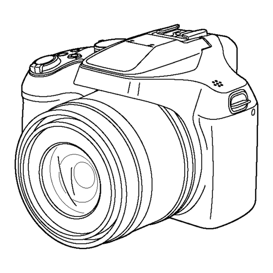
Page 18: Location Of Controls And Components
5 Location of Controls and Components The following description is for DC-FZ82EB. Some descriptions may differ depending on model suffix. The page number in this chapter does not show the page number of this service manual. -
Page 19: Service Mode
6 Service Mode 6.1. Error Code Memory Function 1. General description This unit is equipped with history of error code memory function, and can be memorized 16 error codes in sequence from the latest. When the error is occurred more than 16, the oldest error is overwritten in sequence. The error code is not memorized when the power supply is shut down forcibly (i.e.,when the unit is powered on by the battery, the battery is pulled out) The error code is memorized to Flash-ROM when the unit has just before powered off. - Page 20 Error Code List The error code consists of 8 bits data and it shows the following information. Attribute Main item Sub item Error code Contents (Upper) Error Indication High Check point (Lower) Detecting Part/Circuit 4 bits 4 bits device LENS Lens drive Focus 1C*0...
- Page 21 Attribute Main item Sub item Error code Contents (Upper) Error Indication High Check point (Lower) Detecting Part/Circuit 4 bits 4 bits device Adj.History 1D*0 2000 OIS adj. Yaw direction amplitude error (small) OIS ADJ OIS ADJ 3000 OIS adj. Pitch direction amplitude error (small) 4000 OIS adj.
- Page 22 Important notice about "Error Code List" 1) About "*" indication: The third digit from the left is different as follows. • In case of 0 (example: 18001000) When the third digit from the left shows "0", this error occurred under the condition of Initial Settings has been completed.
-
Page 23: Troubleshooting Guide
7 Troubleshooting Guide 7.1. Wi-Fi Circuit (Flash P.C.B. Unit) 7.1.1. How to Remove Wi-Fi Password Protection To prevent incorrect operation or use of the Wi-Fi function by a third party and to protect saved personal information, this unit protects the Wi-Fi function with a password. It is unable to service with password locked condition. -
Page 24: Service Fixture & Tools
8 Service Fixture & Tools 8.1. Service Fixture and Tools The following Service Fixture and tools are used for checking and servicing this unit. -
Page 25: When Replacing The Main P.c.b
8.2. When Replacing the Main P.C.B. After replacing the Main P.C.B., be sure to achieve adjustment. 8.3. Service Position This Service Position is used for checking and replacing parts. Use the following Extension cables for servicing. Table S1 Extension Cable List Parts No. -
Page 26: Disassembly And Assembly Instructions
9 Disassembly and Assembly Instructions 9.1. Disassembly Flow Chart This is a disassembling chart. When assembling, perform this chart conversely. 9.2. P.C.B. Location... -
Page 27: Disassembly Procedure
9.3. Disassembly Procedure Item Fig. Removal Hot Shoe FPC Unit, Fig. D15 Screw (K) × 2 Item Fig. Removal MIC FPC Unit, Screw (L) × 2 Rear Case Unit Fig. D1 Memory Card Flash Unit Hot Shoe FPC Unit Battery Fig. - Page 28 9.3.1. Removal of the Rear Case Unit Fig. D2 Fig. D1...
- Page 29 9.3.2. Removal of the Main P.C.B. Fig. D3 Fig. D4...
- Page 30 9.3.3. Removal of the Top Operation Unit 9.3.4. Removal of the Battery Case Unit, LVF Unit, Flash Unit Fig. D5 Fig. D6...
- Page 31 9.3.5. Removal of the Lens Unit 9.3.7. Removal of the LCD Unit Fig. D7 9.3.6. Removal of the Strap Holder R, Front Earth Plate and Lens Ring Front Fig. D8 Fig. D9...
- Page 32 9.3.8. Removal of the Battery Door Unit, 9.3.9. Removal of the Flash P.C.B. Unit Jack Cover and Coupler Cover Fig. D10 Fig. D11...
- Page 33 9.3.10. Removal of the SD Earth Plate, Flash Earth Plate and Jack Earth Plate Fig. D13 Fig. D12...
- Page 34 9.3.11. Removal of the LVF Unit 9.3.12. Removal of the Hot Shoe FPC Unit, MIC FPC Unit, Flash Unit Fig. D14 Fig. D15...
- Page 35 Fig. D17 Fig. D16...
-
Page 36: Lens Disassembly Procedure
9.4. Lens Disassembly Procedure Precaution: 1. Do not remove the MOS when disassembling or re- assembling the lens in order to maintain it clean. When remove it, refer to item "9.5.". 2. Keep dust or dirt away from the lens. 3. - Page 37 9.4.2. Removal of the 6th Lens Frame Unit 1. Turn the gear part of Cam Frame Unit in the direction of arrow fully. 2. Pull out the 6th Lens Frame Unit using tweezers, etc.
- Page 38 9.4.3. Removal of the 5th Lens Frame Unit 9.4.4. Removal of the 1st Lens Frame Unit and 2nd Lens Frame Unit 1. Turn the gear part of Cam Frame Unit in the direction of arrow fully. 1. Turn the gear part of Cam Frame Unit in the direction of 2.
- Page 39 9.4.5. Removal of the Middle Frame Unit 1. Remove the Middle Frame Unit in the direction of arrow.
- Page 40 9.4.6. Removal of the Focus Motor Unit 1. Remove the 2 Screws (B) to remove the Focus Motor Unit.
- Page 41 9.4.7. Removal of the 4th Lens Frame Unit 1. Remove the 4th Lens Frame Unit in the direction of arrow.
- Page 42 9.4.8. Removal of the 3rd Lens Frame Unit 1. Remove the 3rd Lens Frame Unit in the direction of arrow.
- Page 43 9.4.9. Removal of the Zoom Motor Unit and Lens Flex 1. Remove the 2 Screws (C). 2. Remove the 2 Screws (D). 3. Remove the 1 tab turn. 4. Remove the Lens Flex from positioning boss to remove the Zoom Motor Unit and Lens Flex. 5.
-
Page 44: Removal Of The Mos Unit
9.5. Removal of the MOS Unit When remove the MOS Unit once (the Torx screw (A) is loosened even a little), the optical tilt adjustment is required. When loosen the Torx screw (A), necessary the optical tilt adjustment at the end of assembling. (Refer to item "10.3.2.") To prevent the MOS Unit from catching the dust and dirt, do not remove the MOS Unit except for replacing. -
Page 45: Measurements And Adjustments
10 Measurements and Adjustments 10.1. Introduction When servicing this unit, make sure to perform the adjustments necessary based on the part (s) replaced. When trouble occurs, it is recommended to backup the Flash-rom data before disassembling the unit. NOTE: (When replacing the Lens unit, Cam Frame Kit and MOS Unit) •... - Page 46 10.2.2. Flash-ROM Data Backup Number of necessary adjustment items decreases by copying the backup data to new Main P.C.B. when adjustment data in old Main P.C.B. is usually read by ROM_BACKUP "DSCSD". It is recommended to backup the Flash-ROM data as the way of return when trouble occurs before disassembling the unit depending on each case.
- Page 47 10.2.3. About Light Box How to remove the Front Hood In order to utilize maximum of the diffusing surface of light box, some adjustment items need the distance between diffusing surface of light box and camera body becomes several cent-meters. Before the adjustments, remove the front hood of light box following steps below.
-
Page 48: Details Of Electrical Adjustment
10.3. Details of Electrical Adjustment 10.3.1. How to execute the Electrical Adjustment It is not necessary to connect the camera to a PC to perform adjustments. "Flag reset operation" and "Initial setting operation" are required when carrying out the alignment, follow the procedure below. 10.3.1.1. - Page 49 10.3.1.3. Execute Adjustment (In case of "OIS Adjustment") 1. Perform step "10.3.1.1." to "10.3.1.2.", to reset the OIS flag status "F" (Set) to "0" (Reset) 2. Press [ DISP. ] button after Flag reset. OIS Adjustment screen is displayed on the LCD panel. (Refer to Fig.3-3) 3.
- Page 50 10.3.2. Adjustment Specifications The following matrix table shows the relation between the replaced part and the Necessary Adjustment. When a part is replaced, make sure to perform the necessary adjustment(s) in the order indicated. The table below shows all the information necessary to perform each adjustment.
-
Page 54: After Adjustment
*1. This adjustment must be performed not only replacing the MOS unit, but also simply removing the MOS unit. *2. The pixel that always lights while shaded is called a white wound. *3. The pixel that does not light while complete exposed is called a black wound. *4: If the adjusted data is backed up from the main board before replacement or repair, write the data to the new main board. -
Page 55: Maintenance
11 Maintenance 11.1. Cleaning Lens and LCD Panel Do not touch the surface of lens and LCD Panel with your hand. When cleaning the lens, use air-blower to blow off the dust. When cleaning the LCD Panel, dampen the lens cleaning paper with lens cleaner, and the gently wipe the its surface. NOTE: The Lens Cleaning Kit ;... -
Page 57: Block Diagram
12 Block Diagram 12.1. Overall Block Diagram (24mm - 1200mm, 60) IC3101 CARD 1/2.3" 18 MEGA PIX IC6003 (72MHz) ZOOM IRIS SHUTTER OIS UNIT FOCUS FLASH ROM /1Gbit COLOUR LCD IC9101 PANEL MOTOR DRIVE, OIS DRIVE & 3.0" PANEL PRE PROCESS 1.04M PIX (Type of LCD Driver inclusion) IC7101... -
Page 58: System Control Block Diagram
12.2. System Control Block Diagram IC6001 (VENUS ENGINE) REAR OPERATION UNIT TOP OPERATION UNIT CD9010 (REAR KEYIN2) (MODE AD1) FP9007 FP9002 EVF/LCD ADO IN8 ADO IN9 MODE DIAL FP9007 AF/AE LOCK FP9002 FP9007 AF/ME (REAR KEYIN1) FP9007 PLAY BACK ADO IN5 FP9007 DISPLAY CD9006... -
Page 59: Video/Audio Process Block Diagram
12.3. Video/Audio Process Block Diagram IC6001 IC6003 LCD UNIT (VENUS ENGINE, SDRAM) (NAND FLASH/1Gbit) (Type of LCD Drive inclusion) 4Gbit(2Gbitx2) FP9003 X-BUFFERS TP INT A9-A25 LATCHES NAND FLASH FP9003 & DECODERS ARRAY TP SCL BANK0 BANK2 Y-BUFFERS FP9003 A0-A7 TP SDA LATCHES PAGE REGISTER &... -
Page 60: Lens/Flash Block Diagram
12.4. Lens/Flash Block Diagram LENS UNIT IC6001 (VENUS ENGINE) FP9004 CO. BARREL & FOCUS ENC FLASH P.C.B. UNIT (G FHP) AD2 IN2 (G ZHP) CD8001 CD8003 AD2 IN3 T8001 FHP LED D8002 IP8001 PS9001 PP8001 CL8024 ZHP LED UNREG 16-19 16-19 IC9101 CD8006... -
Page 61: Power(1) Block Diagram
12.5. Power(1) Block Diagram CD1595 CD9401 P9001 IP9001 (UNREG) BAT+ UNREG (BAT THERMO) IC1511 IC1510 THERMO (REGULATOR) (REGULATOR) (BAT-D) BATTERY BAT D D1501 VOUT VOUT SUB D+3.0V BAT- IC1503 PW SD+3.1V CD1501 (USB SWITCH) JK2001 CD6502 (2S1) USB TERMINAL IP2001 QR6502 VBUS (G_USB-) -
Page 62: Power(2) Block Diagram
12.6. Power(2) Block Diagram UNREG UNREG CD1040 PW DRAM+1.22V CD1010 PW REF+1.22V PW D+3.6V IC1210 IC1110 (REGULATOR) (REGULATOR) CD1210 CD1110 IC1001 4 VIN VOUT 4 VIN VOUT PW A+3.1V (4CH SWITCHING REGULER) 3 CE VSS 2 3 CE VSS 2 PW GYRO+3.1V PVCC1 PWMCOMP1... -
Page 63: Wiring Connection Diagram
13 Wiring Connection Diagram 13.1. Interconnection Diagram LENS SPEAKER UNIT LCD UNIT LVF UNIT UNIT HOT SHOE FPC UNIT CL9406 (RED) CL9407 (BLACK) HOT SHOE FP9010 MIC_GND MIC_L_IN MICROPHONE MIC_GND MIC FPC UNIT MIC_R_IN REAR OPERATION UNIT FP9007 CMD_DIAL_FO EVF_LCD AE_AF_LOCK AF/MF KURUPON... -
Page 65: Schematic Diagram
14 Schematic Diagram Please click the radio button for "Diagrams II / Parts List" on the menu bar in XML Service Manual. If you want to print, please click the icon button for "Print" on the icon bar and select the item. 15 Printed Circuit Board Please click the radio button for "Diagrams II / Parts List"...
Need help?
Do you have a question about the LUMIX DC-FZ80P and is the answer not in the manual?
Questions and answers