Table of Contents
Advertisement
Quick Links
Advertisement
Table of Contents

Summary of Contents for WATT Enware Aquablend 1000
- Page 1 Enware Aquablend 1000 ® Thermostatic Mixing Valve Installation Instructions For use in Australia ATM710 15mm Inlet with 15/20mm Outlet ATM712 20mm Inlet with 20/25mm Outlet AS4032.1 WMKA25301 I00517_05 Apr 2024 1300 369 273 | info@enware.com.au enware.com.au...
- Page 2 Aquablend 1000 Thermostatic Mixing Valve The Enware Aquablend PRODUCT FEATURES 1000 Thermostatic Mixing • Complies with the requirements of AS4032 - Valve is a high performance Thermostatic Mixing Valves Thermostatic Mixing Valve • Provides high stability of suitable for a wide range of mixed water temperature applications.
-
Page 3: Table Of Contents
Aquablend 1000 Thermostatic Mixing Valve CONTENTS Safety page 4 Product Description page 5 Recommended Pressures page 7 and Temperatures Flow Sizing Graph page 8 Installation page 9 Commissioning of the Valve page 11 Maintenance & Servicing page 14 Troubleshooting page 16 Spare Parts page 18 Commissioning Report... -
Page 4: Safety
SAFETY The Enware Aquablend 1000 Thermostatic Mixing Valve is a high performance valve designed to give stable and dependable operation, provided it is installed, commissioned, operated and maintained as per the recommendations outlined in this manual. It should be noted however that this valve should not be considered as an alternative to adequate supervision and duty of care during its use and operation. -
Page 5: Product Description
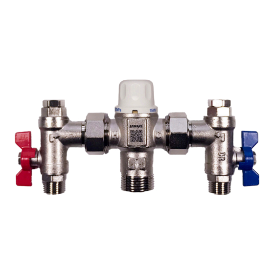
PRODUCT DESCRIPTION The Enware Aquablend 1000 Thermostatic Mixing Valve is available complete with inlet service fittings. The service fittings consist of isolating ball valves, strainers, pressure test points and non-return valves. The strainers can be serviced and cleaned without disturbing the installation (refer to Maintenance and Servicing section). - Page 6 PRODUCT DESCRIPTION Method of operation is illustrated in IMAGE 2 below: Hot and cold water is supplied to each side of the valve respectively. The hot water enters through a port below the Piston, the cold water enters above the Piston. Upon entry the water begins to blend and enters the Mixing Tube.
-
Page 7: Recommended Pressures
RECOMMENDED PRESSURES & TEMPERATURES MIXED OUTLET TEMPERATURE 38 - 50°C Temperature Adjustment Range Set during installation/commissioning | Factory set at 40°C (+/- 2 ˚C) INLET TEMPERATURES Cold Supply Minimum 5°C Maximum 30°C^ Hot Supply Minimum 55°C Maximum 90°C Hot to Mix Temperature Differential for Minimum 10°C Stable Operation... -
Page 8: Flow Sizing Graph
FLOW SIZING GRAPH The Enware Aquablend 1000 Thermostatic Mixing Valve is suitable for many applications. The Headloss Characteristic for Mixed Outlet Flow Rate versus Balanced Inlet Pressure is shown below in IMAGE 3. It is important that the valve is not oversized for its intended application. -
Page 9: Installation
Standard, Code and legislation applicable to each state and following the details outlined in this section. The Enware Aquablend 1000 must be installed by a licensed plumber, or where applicable, a licensed plumber who has undertaken TAFE training in Thermostatic Mixing Valves. - Page 10 INSTALLATION The water quality conditions should be checked to ensure they do not exceed the limits as listed in AS3500.4 Section 1.6. If they do exceed the limits it will be necessary to install a water softener or water treatment device. NOTE: In some installations where certain types of faucet devices such as flick mixers and solenoid valves are used, the water pressure may be seen to spike outside that...
-
Page 11: Commissioning Of The Valve
COMMISSIONING OF THE VALVE Upon completion of the installation, the valve should be tested and commissioned as per the procedure outlined below or as specified by the local authority. The entire procedure should be read through thoroughly prior to the commissioning of the valve. - Page 12 COMMISSIONING OF THE VALVE 3. Fit supplied key over the adjusting spindle. SEE IMAGE 7 • To increase the mixed outlet temperature, rotate the spindle anti-clockwise. • To decrease the mixed outlet temperature, rotate the spindle clockwise 4. Allow the mixed outlet temperature to stabilize for 60 seconds and once again take a temperature reading.
- Page 13 COMMISSIONING OF THE VALVE SHUT DOWN TEST Now that the mixing valve has been set and locked it is necessary to perform a shut down check. Allow the mixed water temperature to stabilise and note the outlet temperature. While holding a digital thermometer in the outlet flow, quickly isolate the cold water supply to the valve.
-
Page 14: Maintenance & Servicing
ANNUAL MAINTENANCE PROCEDURE Every 12 months, the Enware Aquablend 1000 should be inspected and tested. The valve’s external surfaces should be given a light wipedown. The valve and surrounding area should be inspected for leaks or water damage and action taken if required. - Page 15 MAINTENANCE AND SERVICING Non-Return Valve Operation To check Non-Return Valve on the HOT inlet side, carry out the following steps: 1. Turn OFF the isolation tap on the HOT inlet only (COLD inlet must be open) 2. Open Test Port Cap on the HOT inlet side 3.
-
Page 16: Troubleshooting
TROUBLESHOOTING FAULT/ CAUSE RECTIFICATION SYMPTOM The desired • Hot and cold supplies • Refit the valve with Hot/ mixed water are fitted to the wrong Cold supplies fitted to the temperature connections correct connections cannot be • Valve contains debris •... - Page 17 TROUBLESHOOTING FAULT/ CAUSE RECTIFICATION SYMPTOM Either full • Valve is incorrectly set. • Adjust mix temperature hot or cold • Hot/Cold water has between 38 - 50°C as flowing from migrated to other inlet. required. outlet fixture • Refer also to fault/symptom •...
-
Page 18: Spare Parts
SPARE PARTS PART REPLACEMENT TIME PART NUMBER 5 Year Service Kit (includes O-rings, 5 years ATMS242L element and piston assembly) O-Ring Kit when required ATMS123 OLD STYLE Pressure Test Point Lock Shield Plug with Washer (Each) 5 YEAR ATMS1314 SERVICE KIT Pressure Test Point ATMS242L Washer Only (Each) -
Page 19: Commissioning Report
COMMISSIONING REPORT Enware Thermostatic Mixing Valve Commissioning Report For Thermostatic Mixing Valves use a separate sheet for each valve Establishment Address Phone No Contact Work Order Date Make & Model of Hot Water Unit Pressure Pressure Hot Water Cold Water ˚C ˚C Temp... - Page 20 COMMISSIONING REPORT Test results (complete table on following page) Valve considered satisfactory for use YES/NO If NO, state reason and action taken It is hereby certified that all the commissioning work has been carried out by the undersigned in accordance with local plumbing requirements for Thermostatic Mixing Valves Date initial service due: (Maximum...
- Page 21 COMMISSIONING REPORT Test results Valve location/building Room or area designation Work Order No Warm Name/type/ Flow rate of design Temp of warm water water size & location warm water (L/sec) °C outlet of outlet fixture 1 outlet ** All req. 1 outlet ** All req.
-
Page 22: Servicing Report
SERVICING REPORT Enware Thermostatic Mixing Valve Servicing Report use a separate sheet for each valve Establishment Address Phone No Contact Date Work Order No. Make & Model of Hot Water Unit Model No: Mixing Valve Make: Size Valve Location / Building Total No. - Page 23 SERVICING REPORT It is hereby certified that all the commissioning work has been carried out by the undersigned in accordance with local plumbing requirements for Thermostatic Mixing Valves Lic/Cert No Signature Licensed Plumber Business name of Plumbing Contractor Date Contractors Authority No NOTE: A duplicate copy of this report is to be retained at the site for any inspection by authorised persons.
- Page 24 www.enware.com.au © Enware Pty Ltd...
- Page 25 Product Warranty Statement - WATTS AUSTRALIA EFFECTIVE FROM 20 November 2023 This Warranty Statement applies to products supplied by Australian Valve Group Pty Ltd (ACN 068 227 270) (AVG) or Enware Pty Ltd (ACN 662 302 767) (Enware) (each of AVG and Enware, a Supplier) and installed within Australia.
-
Page 26: Warranty
3. Our responsibilities (a) In the event that the Supplier is reasonably satisfied that there is a defect in the relevant Product within the applicable Warranty Period, the Supplier will, at its option, replace the Product, supply an equivalent product or repair the Product, free of charge. Your costs in making a warranty claim under this Warranty Statement, including any costs in relation to freight, collection, delivery and installation, are to be borne and paid by you. - Page 27 © Enware Pty Ltd www.enware.com.au...
- Page 28 1300 369 273 info@enware.com.au enware.com.au...
Need help?
Do you have a question about the Enware Aquablend 1000 and is the answer not in the manual?
Questions and answers