
Related Manuals for Ruijie RG-S7800C-X Series


Summary of Contents for Ruijie RG-S7800C-X Series
- Page 1 Ruijie RG-S7800C-X Series Switches Hardware Installation and Reference Guide Document Version: V1.13 Date: 2023.05.06 Copyright © 2023 Ruijie Networks...
- Page 2 All rights are reserved in this document and this statement. Any reproduction, excerption, backup, modification, transmission, translation or commercial use of this document or any portion of this document, in any form or by any means, without the prior written consent of Ruijie Networks is prohibited.
- Page 3 Preface Intended Audience This document is intended for: Network engineers Technical support and servicing engineers Network administrators Technical Support Ruijie Networks Website: https://www.ruijienetworks.com/ Technical Support Website: https://ruijienetworks.com/support Case Portal: https://caseportal.ruijienetworks.com Community: https://community.ruijienetworks.com ...
- Page 4 Caution An alert that calls attention to essential information that if not understood or followed can result in function failure or performance degradation. Note An alert that contains additional or supplementary information that if not understood or followed will not lead to serious consequences.
-
Page 5: Product Overview
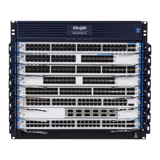
Hardware Installation and Reference Guide Product Overview Product Overview RG-S7810C-X series switches are next-generation core switches developed by Ruijie Networks based on the Clos architecture. They support dual supervisor modules and power module redundancy. The RG-S7810C-X provides two supervisor module slots, eight service module slots, four switch fabric module slots, four power module slots, and two fan module slots. - Page 6 Hardware Installation and Reference Guide Product Overview Power Module The power module redundancy of the same model is supported. Redundancy Fan Module M10C-FAN EMC Standard GB/T 9254.1 Safety Standard GB 4943.1 Long-term operating height: 3,000 m (9842.52 ft.) at 50° C (122° F) The temperature decreases by 1°...
-
Page 7: Product Appearance
Hardware Installation and Reference Guide Product Overview Caution In a domestic environment, this product may cause radio interference in which case the user may be required to take adequate measures. Caution Risk of electric shock. The fuse is on the midline of the grid power supply. Cut off the grid power supply to disconnect each phase of the conductor. - Page 8 Hardware Installation and Reference Guide Product Overview 1. Front Panel Figure 1-2 shows the rear panel of the RG-S7810C-X. Figure 1-2 Front Panel of the RG-S7810C-X Note: System status LED Cable management bracket Service module slot Anti-static wrist strap socket 2.
- Page 9 Hardware Installation and Reference Guide Product Overview The module is powered off. Solid red The module is faulty. Supervisor module 2 Blinking The module is being initialized. If the LED status green blinks continuously, a fault occurs. Solid The module has been initialized and is green working.
- Page 10 Hardware Installation and Reference Guide Product Overview Figure 1-3 Rear Panel of the RG-S7810C-X Note: Power module slot Fan module slot Supervisor module slot Grounding point Switch fabric module slot Caution Ensure that supervisor modules, service modules, and power modules are removed from the chassis before you move or transport the RG-S7810C-X chassis.
- Page 11 Hardware Installation and Reference Guide Product Overview support power management. The supervisor module of the RG-S7810C-X can read power supply information and implement flexible and intelligent power management. Note The RG-S7810C-X supports N+N redundancy of power modules. To improve system stability and reliability, you are advised to configure power module redundancy.
- Page 12 Hardware Installation and Reference Guide Product Overview Figure 1-5 Air Outlet of the RG-S7810C-X Note: 2/3. Air outlet of the service Air outlet of the power module module/supervisor module/switch fabric module Power module: The front-to-rear airflow is used. The fan modules draw air for forced convection. Service module: The right-to-rear airflow is used.
-
Page 13: System Modules
Hardware Installation and Reference Guide System Modules System Modules The RG-S7810C-X adopts the modular design. System modules are independent because they are assigned properly and module interfaces are unified. M7810C-CM-X The supervisor module M7810C-CM-X provides management and switching functions. 1. Module Appearance Figure 2-1 Appearance of the M7810C-CM-X 2. - Page 14 Hardware Installation and Reference Guide System Modules Note Long or short press: Each time you press the FUNC button, the system is triggered to collect information. The device does not restart during information collection, and restarts after the collection is completed. For the short press, the Status LED blinks green, and the system restarts after information collection.
- Page 15 Hardware Installation and Reference Guide System Modules System faults cause the system or module to Solid red fail to work, or the device may be damaged if it continues to work. Temperature alarm affects system running Solid yellow performance, but the system can continue to work.
- Page 16 Hardware Installation and Reference Guide System Modules SDRAM DDR4 4 GB External Port 1 x console port, 1 x 10/100/1000M MGMT port, and 1 x USB port Button 1 x FUNC button Maximum Power 60 W Consumption Hot Swapping Supported Supervisor Module Supported...
- Page 17 Hardware Installation and Reference Guide System Modules This device is not suitable for use in locations where children are likely to be present. M7800C-48GT4XS-XA 1. Module Appearance Figure 2-2 Appearance of the M7800C-48GT4XS-XA 2. External Ports The M7800C-48GT4XS-XA provides 48 x 10/100/1000BASE-T RJ45 ports and 4 x SFP+ ports. The RJ45 port supports the rate of 10/100/1000 Mbps and auto-negotiation.
- Page 18 Hardware Installation and Reference Guide System Modules Solid green The port is connected. Blinking The port is transmitting and receiving data. Table 2-2 Technical Specifications Model M7800C-48GT4XS-XA Quad-core CPU BootROM 16 MB Flash Memory 8 GB SDRAM DDR4 4GB External Port 48 x 10/100/1000BASE-T RJ45 ports and 4 x SFP+ ports 10/100/1000BASE-T CAT5 UTP...
- Page 19 Hardware Installation and Reference Guide System Modules Storage –40° C to +70° C (–40° F to +158° F) Temperature Operating 10% to 90% RH (non-condensing) Humidity Storage 5% to 95% RH (non-condensing) Humidity MTBF 329,000 hours Weight 3.0 kg (6.61 lbs) Dimensions (W 438.5 mm x...
- Page 20 Hardware Installation and Reference Guide System Modules Solid green The module is operational The port is not connected. Solid green The port is connected at the rate of 1000 Mbps. SFP port LED Link/ACT Solid yellow The port is connected at the rate of 100 Mbps.
- Page 21 Hardware Installation and Reference Guide System Modules XG-SFP-AOC1M 1 m SFP+ AOC XG-SFP-AOC3M 3 m SFP+ AOC XG-SFP-AOC5M 5 m SFP+ AOC Status, Link/ACT Supported Swapping Maximum Power 117 W Consumption GB/T 9254.1 Standard Safety GB 4943.1 Standard Operating 0° C to 50° C (32° F to 122° F) Temperature Storage –40°...
- Page 22 Hardware Installation and Reference Guide System Modules 2. External Ports M7800C-52XS-XB provides 52 x SFP+ ports, and supports 10GE SFP+ modules and 1GE SFP modules, and hot swapping. Note M7800C-52XS-XB supports 10GE SFP+ modules and 1GE SFP modules, but 10GE SFP+ modules cannot be used as 1GE SFP modules.
- Page 23 Hardware Installation and Reference Guide System Modules Flash 8 GB Memory SDRAM DDR4 4 GB Port Type 52 x SFP+ ports 1000BASE-SX (850 nm) 1000BASE-LX (1310 nm) 1000BASE-LH (1310 nm) 1000BASE-ZX (1550 nm) 10GBASE-SR (850 nm) 10GBASE-LR (1310 nm) Transmission Media 10GBASE-ER (1550 nm) 10GBASE-ZR (1550 nm)
- Page 24 Hardware Installation and Reference Guide System Modules Storage 5% to 95% RH (non-condensing) Humidity MTBF 285,000 hours Weight 3.55 kg (7.83 lbs) Dimensions 438.5 mm x 346.0 mm x 40.1 mm (17.26 in. x 13.62 in. x 1.58 in.) (W x D x H) M7800C-32XS-XA 2.XX 1.
- Page 25 Hardware Installation and Reference Guide System Modules Solid green The port is connected at the rate of 1000 Mbps. Solid yellow The port is connected at the rate of 100 Mbps. Blinking The port is transmitting and receiving data. The port is not connected. Solid green The port is connected.
- Page 26 Hardware Installation and Reference Guide System Modules Supported Swapping Maximum Power 149 W Consumption GB/T 9254.1 Standard Safety GB 4943.1 Standard Operating 0° C to 50° C (32° F to 122° F) Temperature Storage –40° C to +70° C (–40° F to +158° F) Temperature Operating 0% to 90% RH (non-condensing)
- Page 27 Hardware Installation and Reference Guide System Modules The module is powered off. Solid red The module is faulty. System LED Status The module is being initialized. If the Blinking green LED blinks continuously, a fault occurs. Solid green The module is operational The port is not connected.
- Page 28 Hardware Installation and Reference Guide System Modules Maximum Power 240 W Consumption GB/T 9254.1 Standard Safety GB 4943.1 Standard Operating 0° C to 50° C (32° F to 122° F) Temperature Storage –40° C to +70° C (–40° F to +158° F) Temperature Operating 10% to 90% RH (non-condensing)
- Page 29 Hardware Installation and Reference Guide System Modules 3. LEDs Panel Status Description Identification The module is powered off. Solid red The module is faulty. System LED Status The module is being initialized. If the Blinking green LED blinks continuously, a fault occurs. Solid green The module is operational The port is not connected.
- Page 30 Hardware Installation and Reference Guide System Modules GB/T 9254.1 Standard Safety GB 4943.1 Standard Operating 0° C to 50° C (32° F to 122° F) Temperature Storage –40° C to +70° C (–40° F to +158° F) Temperature Operating 10% to 90% RH (non-condensing) Humidity Storage 5% to 95% RH (non-condensing)
- Page 31 Hardware Installation and Reference Guide System Modules The module is being initialized. If the Blinking green LED blinks continuously, a fault occurs. Solid green The module is operational. The port is not connected. The port is connected at the rate of 1000 Solid green Mbps.
- Page 32 Hardware Installation and Reference Guide System Modules Storage –40° C to +70° C (–40° F to +158° F) Temperature Operating 5% to 95% RH (non-condensing) Humidity Storage 5% to 95% RH (non-condensing) Humidity Weight 3.75 kg Dimensions 438.5 mm x mm x 40.1 (W x D x H)
- Page 33 Hardware Installation and Reference Guide System Modules The port is transmitting and receiving Blinking data. Table 2-9 Technical Specifications Model M7800C-8SFX-XB Quad-core CPU BootROM 16 MB Flash 8 GB Memory SDRAM DDR4 4 GB Port Type 8 x SFX ports (64 x 10GE logical ports) SFG-LR-SM Transmission Media...
- Page 34 Hardware Installation and Reference Guide System Modules Weight 3.85 kg (8.49 lbs) Dimensions 438.5 mm x 346.0 mm x 40.1 mm (17.26 in. x 13.62 in. x 1.58 in.) (W x D x H) 2.10 M78-PSE-X 1. Module Appearance Figure 2-10 Appearance of the RG-M78-PSE-X 2.
- Page 35 Hardware Installation and Reference Guide System Modules EMC Standard GB/T 9254.1 Safety GB 4943.1 Standard Operating 0° C to 50° C (32° F to 122° F) Temperature Storage –40° C to +70° C (–40° F to +158° F) Temperature Operating 10% to 90% RH (non-condensing) Humidity Storage...
- Page 36 Hardware Installation and Reference Guide System Modules Switching service is in progress. The module cannot be removed. Offline Release the OFL button and wait for 2s Solid green before removing the module. Table 2-11 Technical Specifications Model M7810C-FE-X I Quad-core CPU BootROM 16 MB Flash...
- Page 37 Hardware Installation and Reference Guide System Modules Dimensions 371.0 mm x 285.0 mm x 43.0 mm (14.61 in. x 11.22 in. x 1.69 in.) (W x D x H) 2.12 M7810C-FE-X II 1. Module Appearance Figure 2-12 Appearance of the M7810C-FE-X 2.
- Page 38 Hardware Installation and Reference Guide System Modules SDRAM DDR4 4 GB Status Maximum Power 160 W Consumption Hot Swapping Supported EMC Standard GB/T 9254.1 Safety Standard GB 4943.1 Operating Temperature 0° C to 50° C (32° F to 122° F) –40°...
- Page 39 Hardware Installation and Reference Guide System Modules 2. External Ports RG-PA1600I provides 12 V AC input for the RG-S7810C-X. The front panel has a three-pin power connector for connecting a standard 16 A power cord. 3. LEDs Description DC/FLT Solid green Solid green Normal operation Solid red...
- Page 40 Hardware Installation and Reference Guide System Modules Risk of electric shock. The fuse is on the midline of the grid power supply. Cut off the grid power supply to disconnect each phase of the conductor. The maximum operating and storage altitudes are both 4,000 m (13123.36 ft.). 2.14 RG-PA600I 1.
- Page 41 Hardware Installation and Reference Guide System Modules Solid green Solid red PSR ON/OFF control Table 2-14 Technical Specifications Model RG-PA1600I Rated Voltage 100 V AC to 120 V AC, 200 V AC to 240 V AC; 50/60 Hz Range Maximum Voltage 90 V AC to 264 V AC;...
- Page 42 Hardware Installation and Reference Guide System Modules 2.15 RG-PD1600I 1. Module Appearance Figure 2-15 Appearance of the RG-PD1600I 2. External Ports The RG-PD1600I provides one DC (–48 V) power port. 3. LEDs Description DC/FLT Solid green Solid green Normal operation Input power supply (the power module is not plugged Solid green Solid red...
- Page 43 Hardware Installation and Reference Guide System Modules Solid green Solid red Overtemperature protection Solid green Solid red PSR ON/OFF control Solid green Solid red Out-of-phase protection Solid green Solid red Fan failure Table 2-15 Technical Specifications Model RG-PD600I Rated –48 V DC Voltage Range Maximum...
- Page 44 Hardware Installation and Reference Guide System Modules 2.16 RG-PD600I 1. Module Appearance Figure 2-16 Appearance of the RG-PD600I 2. External Ports The RG-PD600I provides one DC (–48 V) power port. 3. LEDs Description DC/FLT Solid green Solid green Normal operation Input power supply (the power module is not plugged Solid green Solid red...
- Page 45 Hardware Installation and Reference Guide System Modules Solid green Solid red Overtemperature protection Solid green Solid red PSR ON/OFF control Solid green Solid red Out-of-phase protection Solid green Solid red Fan failure Table 2-16 Technical Specifications Model RG-PD600I Rated –48 V DC Voltage Range Maximum...
- Page 46 Hardware Installation and Reference Guide System Modules 2.17 RG-PA1600I-PL 1. Module Appearance Figure 2-17 Appearance of the RG-PA1600I-PL The RG-PA1600I-PL provides AC power input for the M78-PSE. 2. External Ports The three-pin connector is located on the M78-PSE. This port can be connected to standard 16 A power cord. For more information about M78-PSE, see M78-PSE.
- Page 47 Hardware Installation and Reference Guide System Modules Solid Solid yellow Overtemperature alarm green Solid red Power-off due to overtemperature Solid red AC power-off Solid red Short circuit Solid red Output undervoltage Solid red Output overvoltage Solid Blinking red Communication failure green Table 2-17 Technical Specifications...
- Page 48 Hardware Installation and Reference Guide System Modules 2.18 M10C-FAN 1. Module Appearance Figure 2-18 Appearance of the M10C-FAN Note: Fan status LED Fan module handle Captive screw of the fan tray 2. Composition The M10C-FAN applies to service modules and supervisor modules on the RG-S7810C. There is one M10C- FAN tray with six fan modules and one fan control board.
- Page 49 Hardware Installation and Reference Guide System Modules Hot swapping Supported...
-
Page 50: Preparing For Installation
Hardware Installation and Reference Guide Preparing for Installation Preparing for Installation Safety Precautions Note To avoid personal injury and device damage, carefully read the safety precautions before you install the RG- S7810C-X. The following safety precautions may not cover all possible dangers. 3.1.1 General Safety Precautions ... - Page 51 Hardware Installation and Reference Guide Preparing for Installation Check whether there are potential risks in the working area. For example, check whether the power supply is grounded properly and whether the ground is wet. Find out the position of the indoor emergency power switch before installation. Cut off the power switch in case of accidents.
- Page 52 Hardware Installation and Reference Guide Preparing for Installation (3) Tighten the buckle till the trap is closely attached to your skin. Warning To ensure safety, use a multimeter to measure the resistance between yourself and the ground, which should be within the range from 1 ohm to 10 ohm. ...
-
Page 53: Installation Site Requirements
Hardware Installation and Reference Guide Preparing for Installation Installation Site Requirements The RG-S7810C-X must be used indoors. The installation site must meet the following requirements to ensure the normal operation and prolonged service life of the device. 3.2.1 Load Bearing Evaluate the load bearing requirements for the ground according to the weight of the switch and its components (such as the cabinet, chassis, line card, and power module). - Page 54 Hardware Installation and Reference Guide Preparing for Installation You are advised to clean it every three months. Clean the air inlet and outlet (including the power module air inlet and outlet) every three months. Clean cards every one to two years. ...
-
Page 55: Power Supply
Hardware Installation and Reference Guide Preparing for Installation be properly protected against the intrusion of harmful gases, such as sulfur dioxide, hydrogen sulfide, nitrogen dioxide, and chlorine gas. Table 3-4 Limit Values for Harmful Gases Average (mg/m Maximum (mg/m Sulfur dioxide (SO Hydrogen sulfide Nitrogen dioxide (NO Chlorine (CI... - Page 56 Hardware Installation and Reference Guide Preparing for Installation M7800C-48SFP4XS-XA M7800C-24GT8SFP8XS-XA M7800C-32XS-XA M7810C-FE-X I M10C-FAN 216 W M7800C-52XS-XB 250 W M7800C-12CQ-XB 240 W M7800C-32XS-XA 2.XX 149 W M7800C-8SFG-XB 250 W M7800C-8SFX-XB 250 W M7810C-FE-X II 160 W M7800C-48XT-P-XB 300 W Note ...
- Page 57 Hardware Installation and Reference Guide Preparing for Installation For the leakage current value of each device model, see the technical specifications in Chapter 1 Product Overview. 3.2.8 Grounding A proper grounding system is the basis for stable and reliable device running. It is indispensable for preventing lightning strikes and interference.
-
Page 58: Cabinet Installation Requirements
Hardware Installation and Reference Guide Preparing for Installation be mitigated by a filter. Radiated interference may affect any signal path in the device, and is difficult to shield against. EMI requirements are as follows: Take interference prevention measures for the power supply system. ... -
Page 59: Installation Tools
Hardware Installation and Reference Guide Preparing for Installation Figure 3-3 Cabinet Size Requirements The guide rails or tray can bear the weight of the device and its accessories. The cabinet has a reliable grounding terminal for the chassis to connect to the ground. ... -
Page 60: Unpacking Requirements
Hardware Installation and Reference Guide Preparing for Installation Unpacking Requirements Table 3-6 Goods Checklist Device panels have been installed and Device panels are installed and operational. commissioned. Chassis Fans, screwdriver, anti-static wrist strap, Fan modules, screwdriver, anti-ESD wrist Carton yellow/green grounding wires, quick strap, yellow/green grounding cables, installation guide, packing list quick installation guide, and packing list... -
Page 61: Product Installation
Hardware Installation and Reference Guide Product Installation Product Installation RG-S7810C-X series Ethernet switch must be used and fixed in the room. Note Make sure you have carefully read part 2 and this part, and be sure that the requirements set forth in part 2 have been met. -
Page 62: Before You Begin
Hardware Installation and Reference Guide Product Installation Before You Begin Carefully plan and arrange the installation position, networking mode, power supply, and cabling before installation. Confirm the following requirements before installation: The installation site provides sufficient space for heat dissipation. ... -
Page 63: Mounting The Cabinet
Hardware Installation and Reference Guide Product Installation Figure 4-1 Mounting the Cable Management Bracket for the RG-S7810C-X Mounting the Cabinet 4.4.1 Precautions When mounting the cabinet, ensure that the following conditions are met: All expansion bolts for fastening the cabinet base to the ground are installed and tightened in sequence from bottom to up (large flat washer, spring washer, and nut), and installation holes on the base and expansion bolts are properly aligned. -
Page 64: Installation Steps
Hardware Installation and Reference Guide Product Installation The device is securely installed, and the screws on the panel are fastened tightly. All wiring outlets at the top and bottom of the cabinet are installed with rodent-resistant nets with clearance of no more than 15 mm (0.59 in.) in the diameter to prevent rodents and other small animals from entering the cabinet. -
Page 65: Mounting The Switch To A Cabinet
Hardware Installation and Reference Guide Product Installation Warning Before installing a guide rail, make sure that the weight of the guide rail meets requirements. There are variable types of guide rails. The guide rail appearance and installation are subject to actual conditions. -
Page 66: System Grounding
Hardware Installation and Reference Guide Product Installation Figure 4-3 Measuring the Mounting Bracket Height and Installation Hole (2) Multiple persons are required to lift the switch from both sides and place it on the cabinet guide rail or tray. Then smoothly push it into the cabinet until the switch's mounting bracket is flush with the square hole rack post in the front. -
Page 67: Connecting The System Ground
Hardware Installation and Reference Guide Product Installation 4.6.1 Precautions The sectional area of the grounding cable should be determined according to the possible maximum current. Cables with good conductor should be used. Do not have bare wires exposed. ... - Page 68 Hardware Installation and Reference Guide Product Installation Note The RG-S7810C-X provides four power module slots. It is recommended that you configure 1+1 power module redundancy. It provides two PoE power module slots. When the RG-S7810C-X uses two or more power modules, the power modules must use the same model.
-
Page 69: Installing A Fan Module
Hardware Installation and Reference Guide Product Installation Installing a Fan Module The RG-S7810C-X provides the heat dissipation system, and the M10C-FAN is the fan module. Before installing a fan module, wear an anti-ESD wrist strap and ensure that it is properly grounded. Procedure for installing the fan module: (1) Install the fan module into the fan slot in the rear panel of the RG-S7810C-X. - Page 70 Hardware Installation and Reference Guide Product Installation 4.9.1 Selecting a Module Slot Note The supervisor module and service module are installed in different slots. Install modules in corresponding positions according to the markings in Figure 4-8. Figure 4-8 RG-S7810C-X Chassis Note: O&M LED Cable management bracket...
- Page 71 Hardware Installation and Reference Guide Product Installation Note: Power module slot Fan module slot Supervisor module slot Grounding stud Switch fabric module slot 4.9.2 Installing a Module The procedure for installing a module of the RG-S7810C-X is as follows: (1) Rotate the ejector levers of the module outward (callout 1 in Figure 4-9). (2) Align the module with the vacant slot and push the module into the slot slowly along the guide rails (callout Caution When installing a supervisor module or switch fabric module, make its PCB face left.
- Page 72 Hardware Installation and Reference Guide Product Installation Figure 4-9 Positions on the RG-S7810C-X Note Install a filler panel in the unoccupied slot for heat dissipation. 4.10 (Optional) Installing Swappable Interface Modules Warning Ensure that optical modules connected to both ends of an optical fiber are of the same type when you replace swappable optical modules.
- Page 73 Hardware Installation and Reference Guide Product Installation 4.10.2 Installing the SFP/SFP Optical Module Note To avoid component damage due to operation errors, read this section carefully before installing the SFP+/SFP optical module. 1. Procedure (1) Pivot the bail clasp up so that it is parallel with the module body. Grasp the module between your thumb and index fingers and slide the module into the slot until you feel the module snap into place.
- Page 74 Hardware Installation and Reference Guide Product Installation 1. Procedure for Installing the SFP+ Electrical Module (1) You can install the SFP+ electrical module with power supply. Hold the connector of the SFP+ electrical module with one hand and hold the cable perpendicular to the front panel of the switch with the other hand. Push the module gently into the SFP+ electrical module slot until you feel the module snap into place.
- Page 75 Hardware Installation and Reference Guide Product Installation Figure 4-13 Bending Radius and Cable Diameter 3. Procedure for Installing the SFP+ Electrical Cable Use an SFP+ cable to connect two SFP+ ports close to each other. Perform the following steps to install the SFP+ electrical cable: (1) Wear an anti-ESD wrist strap and ensure that it is well grounded.
-
Page 76: Connecting Power Cords
Hardware Installation and Reference Guide Product Installation Figure 4-14 Installing the 40GE QSFP or 100GE QSFP28 Module with the Bail Clasp Figure 4-15 Installing the 40GE QSFP or 100GE QSFP28 Module with the Pull-tab (3) Connect the module to the network using an optical cable. Select the optical cable with the connector corresponding to the optical port. -
Page 77: Connecting The Dc Power Cord
Hardware Installation and Reference Guide Product Installation Note Make sure that the socket is powered off before the power cord is connected. (1) Insert the AC power plug into the power receptacle. (2) Take out the power cord retention clip. (3) Install the power cord retention clip on the front panel of the power module. -
Page 78: Checking After Installation
Hardware Installation and Reference Guide Product Installation Warning Before connecting the power module, verify that the external power supply matches the power modules installed on the device. Before connecting the DC power cord to the power terminal block, ensure that the other end of the DC power cord is not powered on or is powered off. - Page 79 Hardware Installation and Reference Guide Product Installation Verify that the power supply is properly selected. Verify that the power module is inserted properly and captive screws are tightly fastened. Do not power up the switch by yourself and do not perform live-line maintenance. ...
-
Page 80: Establishing The Configuration Environment
Hardware Installation and Reference Guide Verifying the Operating Status Verifying the Operating Status Establishing the Configuration Environment Note If you log in to the switch for the first time, use the console port. 5.1.1 Connecting the Console Cable (1) Connect one end of the DB-9 jack of the console cable to the serial port of the PC. (2) Connect one end of the console cable RJ45 to the console port of the supervisor module of the switch. - Page 81 Hardware Installation and Reference Guide Verifying the Operating Status Figure 5-2 Connection Description Dialog Box In the Connection Description dialog box, set the name of the new connection and click OK. A window appears. In the Connect Using field, select the serial port you want to use. Figure 5-3 Connect To Interface Click OK.
-
Page 82: Powering On The Switch
Hardware Installation and Reference Guide Verifying the Operating Status Figure 5-4 COM1 Properties Interface Click OK. The Hyperterminal window will appear. Powering On the Switch 5.2.1 Checklist Before Power-on The switch is fully grounded. The power cord is correctly connected. ... -
Page 83: Monitoring And Maintenance
Hardware Installation and Reference Guide Monitoring and Maintenance Monitoring and Maintenance Monitoring 6.1.1 LEDs When the RG-S7810C-X is running, you can monitor the status of each module by observing the status LED of the corresponding module: When the alarm LED of the active supervisor module is red, the system has a fault, in which case you can log in to the management software to perform troubleshooting. -
Page 84: Troubleshooting Flowchart
Check whether line card is installed properly and secured Check whether LEDs of line cards are normal Check whether serial port is connected correctly and whether its parameters are correct Check whether optical or electrical cables are connected correctly Contact Ruijie technical support personnel... - Page 85 Hardware Installation and Reference Guide Troubleshooting Common Troubleshooting Cases 7.2.1 Fault 1: The AC Power Module Does Not Work 1. Fault Symptom The status LED of each line card is off, the status LED of the fan module is off, the fan module does not work, and the LED on the panel of the power module is off.
- Page 86 (2) Check whether the configuration of the serial port on the HyperTerminal is the same as that of the switch. If not, change serial port configuration parameters. (3) If there is still no serial port information, contact Ruijie technical support personnel. 7.2.7...
- Page 87 (3) Check whether the distance between the two sides exceeds the maximum length marked on the optical module. (4) Check whether the speeds of the two sides match and whether the fiber type meets requirements. If ports support different rates, check whether rates are configured correctly. Note If the fault persists, contact Ruijie technical support personnel.
-
Page 88: Replacing Modules
Hardware Installation and Reference Guide Replacing Modules Replacing Modules Removing, Cleaning, and Installing Air Filter Caution If the air filter has been used for a long time, dust in the air may block air vents of the air filter and affect heat dissipation of the system. - Page 89 Hardware Installation and Reference Guide Replacing Modules Figure 8-2 Removing the SFP+ Electrical Cable 2. Precautions Pull the tab out before unplugging the cables. Otherwise, the module or slot may be damaged. Immediately install the dust plug to the module port and the device optical port. 8.2.3 Removing a 40G QSFP+ or 100G QSFP28 Module 1.
- Page 90 Hardware Installation and Reference Guide Replacing Modules Figure 8-4 Removing the QSFP+ or QSFP28 Module with the Pull-tab 2. Precautions Unplug the optical cable before replacing the module. Do not pull out the module without excessive force before turning down the handle of the module. ...
- Page 91 Hardware Installation and Reference Guide Replacing Modules Figure 8-5 Replacing Service Modules of the RG-S7810C-X Figure 8-6 Replacing Switch Fabric Modules of the RG-S7810C-X...
-
Page 92: Removing A Power Module
Hardware Installation and Reference Guide Replacing Modules Figure 8-7 Replacing Switch Fabric Modules of the RG-S7810C-X Warning To ensure good system ventilation and heat dissipation and prevent dust, install a filler panel in the unoccupied slot. To remove a card when the device is being powered on, you must insert a new card or filler panel within 10 minutes. - Page 93 Hardware Installation and Reference Guide Cables (3) Open the handle on the power module panel and keep the handle perpendicular to the panel. (4) Hold the power module panel with the right hand and the bottom of the power module with the left hand, and slowly pull the power module out of the power module slot.
-
Page 94: Bundling Cables
Hardware Installation and Reference Guide Cables 9.1.2 Steps (1) Connect the RJ45 connector of the Ethernet cable to the Ethernet interface of the device and the other end to the NMS or management terminal; or connect one end of the standard RJ45 serial port cable to the serial port of the device and the other end to the NMS or management terminal. -
Page 95: Appendix A Connectors And Connection Media
Hardware Installation and Reference Guide Appendix A Connectors and Connection Media Appendix A Connectors and Connection Media 10.1 1000BASE-T/100BASE-TX/10BASE-T The 1000BASE-T/100BASE-TX/10BASE-T supports auto-negotiation of three rates and automatic MDI/MDIX crossover at these three rates. Conforming to IEEE 802.3ab, 1000BASE-T requires 100-ohm CAT5 or CAT5e, or higher 100-ohm UTP or STP (recommended) with a maximum distance of 100 m (328.08 ft.). - Page 96 Hardware Installation and Reference Guide Appendix A Connectors and Connection Media Figure 10-3 provides the wiring of straight-through and crossover cables for 100BASE-TX/10BASE-T. Figure 10-4 100BASE-TX/10BASE-T Twisted Pair Connection 10.2 Optical Cable Connections Select single-mode or multimode optical cables according to the module types. Figure 10-5 Optical Cable Connection...
-
Page 97: Appendix B Appendix B Mini-Gbic, 10Ge, 40Ge, And 100Ge
Appendix B Appendix B Mini-GBIC, 10GE, 40GE, and 100GE Modules Ruijie provides 1000M SFP modules (mini-GBIC modules), 10GE XFP modules, and 10GE SFP+ modules. You can select modules to suit your specific needs. The following models and technical specifications of some 1000M SFP modules, 10GE XFP modules, and 10GE SFP+ modules are listed for your reference. - Page 98 Hardware Installation and Reference Guide Appendix B Appendix B Mini-GBIC, 10GE, 40GE, and 100GE Modules FE-SFP-LH15- 1310 9/125 15 km SM1310 62.5/125 275 m Mini-GBIC-SX 50/125 550 m Mini-GBIC-LX 1310 9/125 10 km 62.5/125 275 m GE-eSFP-SX- MM850 50/125 550 m GE-eSFP-LX- 1310 9/125...
- Page 99 Hardware Installation and Reference Guide Appendix B Appendix B Mini-GBIC, 10GE, 40GE, and 100GE Modules – – XG-SFP-LR- SM1310 conne ctor) – – XG-SFP-ER- –1 SM1550 conne ctor) Table 11-4 Models of the 10GE SFP+ Active Module Modu Conne Cable Conductor Data Rate Model...
- Page 100 Hardware Installation and Reference Guide Appendix B Appendix B Mini-GBIC, 10GE, 40GE, and 100GE Modules (1264.5, 1277.5) (1284.5, – 1297.5) 40G-QSFP-LR4- SM1310 (1304.5, 1317.5) (1324.5, 1337.5) Cabling Specifications Table 11-6 of the 40GE QSFP+ Module Core Max. Wavelength Connector Fiber Modal Bandwidth Model Size...
- Page 101 Hardware Installation and Reference Guide Appendix B Appendix B Mini-GBIC, 10GE, 40GE, and 100GE Modules Max. – – 100G-QSFP-SR- (840, 860) MM850 (1236.4, 1277.5) (1284.5, 1297.5) – 100G-QSFP -iLR4- –10 SM1310 (1304.5, 1317.5) (1324.5, 1337.5) (1294.53, 1296.59) – (1299.02, 1301.09) –...
- Page 102 Hardware Installation and Reference Guide Appendix B Appendix B Mini-GBIC, 10GE, 40GE, and 100GE Modules 100G-QSFP-iLR4- MPO/AP (1295,1325) PSM-SM1310 100GE Module Table 11-9 Models of the Optical Conductor Modul Connect Cable Model Diameter Rate (Gbps) (Yes/No e Type or Type Length (AWG) 100G-AOC-1M...
-
Page 103: Appendix C Surge Protection
Hardware Installation and Reference Guide Appendix C Surge Protection Appendix C Surge Protection 12.1 Installing the AC Power Arrester (Surge Protection Power Strip) The AC power port must be connected to an external surge protection power strip. This prevents the switch from being struck by lightning when the AC power cord is introduced from outdoors and directly connected to the power port of the switch. - Page 104 Hardware Installation and Reference Guide Appendix C Surge Protection of the power socket for the arrester when the indicator is red. If the N line is on the left and the L line is on the right (facing the socket), the arrester’s PE terminal is not grounded. If not, the polarity of the arrester power cord should be reversed.
- Page 105 Hardware Installation and Reference Guide Appendix C Surge Protection Figure 12-2 Ethernet Port Arrester Installation Warning The Ethernet port arrester is only for the 10M/100M electrical ports with an RJ-45 connector. The Ethernet port arrester is not delivered with the device. Purchase it as needed. 12.2.3 Precautions The arrester's performance is affected in the following situations:...
-
Page 106: Appendix D Cabling
Hardware Installation and Reference Guide Appendix D Cabling Appendix D Cabling When the RG-S7810C-X is installed in a standard 19-inch cabinet, route cable bundles upward or downward alongside the rack depending on the actual situation in the equipment room. All cable connectors should be placed at the bottom of the cabinet, and cannot be exposed outside. - Page 107 Hardware Installation and Reference Guide Appendix D Cabling Figure 13-1 Bundling Up Cables (1) Route and bundle power, signal, and grounding cables separately. Mixed bundling is not allowed. When they are close to each other, crossover cabling is recommended. In the case of parallel cabling, maintain a minimum distance of 30 mm (1.18 in.) between power cords and signal cables.
- Page 108 Hardware Installation and Reference Guide Appendix D Cabling Figure 13-3 Bundling Up Cables (3) Cables that are not assembled or remaining parts of cables should be folded and placed in a proper position of the cabinet or cable trough. The proper position refers to a position that does not affect device running or damage the switch or cable.
- Page 109 Hardware Installation and Reference Guide Appendix D Cabling When using a stiff cable, fix it near the cable lug to avoid stress on the lug and cable. Do not use self-tapping screws to fasten terminals. Power cords of the same type and in the same cabling direction should be bundled up into cable bunches, with cables in cable bunches clean and straight.
-
Page 110: Appendix E Equipment Room Site Selection
Hardware Installation and Reference Guide Appendix E Equipment Room Site Selection Appendix E Equipment Room Site Selection The equipment room should be at least 5 km (3.11 miles) away from heavy pollution sources, such as the smelter works, coal mines, and thermal power plants. The equipment room should be at least 3.7 km (2.30 miles) away from medium pollution sources, such as the chemical factory, rubber factory, and electroplating factory.
Need help?
Do you have a question about the RG-S7800C-X Series and is the answer not in the manual?
Questions and answers