Table of Contents
Advertisement
Advertisement
Table of Contents

Related Manuals for Sennheiser NET 1


Summary of Contents for Sennheiser NET 1
- Page 1 NET 1 Instructions for use...
-
Page 3: Table Of Contents
60 years of accumulated expertise in the design and manufacture of high-quality electro-acoustic equipment have made Sennheiser a world-leading company in this field. Please take a few moments to read these instructions carefully, as we want you to enjoy your new Sennheiser products quickly and to the fullest. -
Page 4: Important Safety Instructions
The wide blade or the third prong are provided for your safety. If the provided plug does not fit into your outlet, consult an electrician for replacement of the obsolete outlet. -
Page 5: Important Safety Information
Important safety information Warning To reduce the risk of fire or electric shock, do not expose this device to rain or moisture. Do not open the cabinet; dangerous high voltage is present. Refer servicing to qualified personnel only. Caution To prevent fire, shock hazard, or annoying interference, use only the recommended accessories. -
Page 6: Accompanying Documentation
Safety check Upon completion of any service or repairs to this device, ask the service technician to perform safety checks to determine that the device is in safe operating order. Accompanying documentation In addition to these instructions, please also refer to the instructions for use of the rack-mount and portable devices instructions for use of the “Wireless Systems Manager”... -
Page 7: The Net 1 Network System
One NET 1 device with up to 10 connected rack-mount devices is a suitable tool for configuring your system. A second, daisy-chained NET 1 allows you to configure systems comprising up to 20 devices, without the need for a PC. -
Page 8: Delivery Includes
10 RJ 10 data cables 1 RJ 45 Ethernet cable Instructions for use of the NET 1 “NET” stickers to mark the receivers and transmitters that have had the latest firmware installed after you have updated them from the supplied CD-ROM 1 CD-ROM with: - the “Wireless Systems Manager”... -
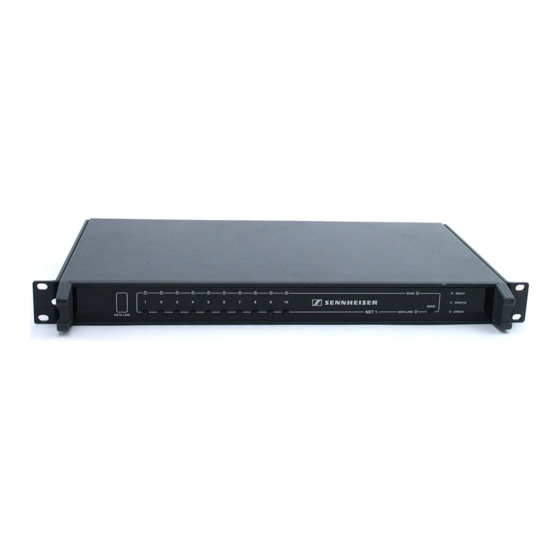
Page 9: Operating Controls
LAN 1 Ethernet connection, Neutrik RJ 45 socket ´ “REMOTE” LED, yellow “DATA” LED, yellow (Ethernet) ² “ERROR” LED, red 10 x RJ 10 socket for connecting rack-mount receivers or transmitters (IEM) of the evolution wireless G2 ¶ MODE button series º... -
Page 10: Leds On The Front Panel Of The Net 1
(IEM) of the correspondingfrequency range, the receivers (IEM) can now be configured..flashes rapidly: NET 1 is ready to transfer the frequencies and settings to a portable device. IR frequency transfer is ...flashes once every second:... -
Page 11: Leds On The Rear Panel Of The Net 1
LEDs on the rear panel of the NET 1 Color of LED LED lights up permanently LED... yellow NET 1 is connected to a PC or an DATA ..flashes rapidly: additional NET 1 Data is being transferred within the network. -
Page 12: Putting The Net 1 Into Operation
Fitting the device feet (“table top” use only) When the NET 1 is not installed in a rack avoid the NET 1 device sliding around and reduce the chance of damage to the device and to any surface on which it is placed by fixing the four soft rubber self adhesive feet to the base of the NET 1 device in the positions indicated. -
Page 13: Connecting The Power Supply
G2 device to the desired RJ 10 socket on the NET 1. When connecting an EM 550 G2 twin receiver, use two cables to connect the individual receivers DATA A / DATA B to two RJ 10 sockets on the NET 1. Note: NET 1 For multi-channel systems, you can daisy-chain several NET 1 devices. -
Page 14: Connecting Several Net 1
RX 2 Connecting several NET 1 Connect two NET 1 via the sockets LAN 1 and LAN 2 using an Ethernet cable. The sockets LAN 1 and LAN 2 are identical, so it doesn’t matter in which order you connect them. -
Page 15: Connecting The Net 1 To A Pc
PC using an Ethernet cable. Notes: It is also possible to connect up to five NET 1 to a PC using a switch or a router with switching function. Do not use a network hub! Attempting to use a hub with NET 1 may cause network failure or other data communications problems. -
Page 16: Switching A Net 1 System On
µ After switch-on, the green “READY” LED flashes, indicating that the NET 1 is being initialized. As soon as the NET 1 is ready for operation, the “READY” LED lights up permanently. If a connected device is detected by the NET 1, the corresponding green “CHANNEL”... -
Page 17: Operation With Systems Of The Evolution Wireless G2 Series
Operation with systems of the evolution wireless G2 series When using devices of the evolution wireless G2 series (see table on page 7), there are two operating modes: 1. “Stand Alone” operating mode (without a PC): one NET 1 with up to 10 connected devices two daisy-chained NET 1 with up to 20 connected devices 2. -
Page 18: Performing A Frequency Scan For Wireless Monitoring Systems (Iem)
Example: ¾ The connection groups 1 to 4 of the NET 1 are occupied by transmitters (IEM). The connection groups 6 to 10 are occupied by rack-mount receivers. After button ¶, the green “CHANNEL“ LEDs ·... - Page 19 300 IEM G2 system). Select a channel bank with a sufficient number of free channels using the rocker button (refer to the instructions for use of the EK 300 IEM G2 receiver). The selected channel bank must have (at least) as many free channels as transmitters (IEM) from this frequency range are connected to the NET 1.
- Page 20 Transferring frequencies to portable receivers (IEM) without a prior frequency scan With the NET 1, you can also transfer the set transmission frequency of a connected rack-mount transmitter (IEM) to the corresponding receiver (IEM) without having performed a frequency scan. To do so, proceed as described in the section “Transferring frequencies to the portable receivers (IEM)”...
-
Page 21: Performing A Frequency Scan For Wireless Microphone Systems
The results of any prior frequency scan are overwritten. Example: The connection groups 1 to 4 of the NET 1 are occupied by transmitters (IEM). The connection groups 6 to 10 are occupied by rack-mount receivers. After button ¶, the green “CHANNEL“ LEDs ·... - Page 22 NET 1. Confirm your selection by pressing the button. The NET 1 assigns the frequencies of the selected channel bank to all rack- mount receivers of the frequency range. The yellow “SCAN” LED goes off and the yellow “DATA LINK”...
- Page 23 º ² With the NET 1, you can also transfer the set receiving frequency of a connected rack-mount receiver to the corresponding transmitter without having performed a frequency scan. To do so, proceed as described in the section “Transferring frequencies to the transmitters without a frequency scan”...
-
Page 24: Operation With 3000/5000 Series Systems
Transferring frequencies to the transmitters without a frequency scan The infrared interface of the SK 5212 portable transmitter is located below the display in the black frame. The infrared interfaces of the SKM 5200 hand- held transmitters and the SKP 3000 plug-on transmitters are located inside the display window of the transmitter. -
Page 25: Mixed Operation Of Evolution Wireless G2 Series Systems And 3000/5000 Series Systems
3000/5000 series systems For information on mixed operation of evolution wireless G2 series systems and 3000/5000 series systems, please refer to the instructions for use of the “Wireless Systems Manager” software. Note: The compander systems are not compatible. Therefore, synchronize only ew G2 transmitters with ew G2 receivers and transmitters of the 3000/ 5000 series with the corresponding receivers (see table on page 7). -
Page 26: If A Problem Occurs
If a problem occurs ... Problems that may occur when putting the NET 1 into operation Problem Possible cause Possible solution ¿ The green “READY” LED The power cord is not connected Check if the power cord is connected gone off. -
Page 27: Problems That May Occur During Operation
PC is disturbed. well as the PC settings. If a problem occurs that is not listed in the above table or cannot be solved with the proposed solutions: Register on the Sennheiser homepage at www.sennheiser.com/net1 and describe the problem in the “Support”... -
Page 28: Specifications
0.4 A Ambient conditions Temperature range: –10 °C to +55 °C Relative humidity: max. 85 % Dimensions approx. 436 x 228 x 43 mm (19“, 1 U) (w/o rack-mount “ears”) Weight approx. 2.6 kg Connections Ethernet LAN 1 and LAN 2... -
Page 29: Accessories/Replacement Parts
Special sub-D cable, Length: 1.5 m 054324 Power cord with EU plug 054325 Power cord with US plug 057256 Power cord with UK plug 086363 Device feet 089540 Rack-mount “ears” 520124 “NET 1” stickers, 100 items CD-ROM including the “Wireless Systems Manager” (WSM) software... -
Page 30: Manufacturer Declarations
In the case of a claim under the terms of this guarantee, send the device, including accessories and sales receipt, to the responsible service partner. To minimise the risk of transport damage, we recommend that the original packaging is used. - Page 32 Sennheiser electronic GmbH & Co. KG 30900 Wedemark, Germany Phone +49 (5130) 600 0 Fax +49 (5130) 600 300 www.sennheiser.com Printed in Germany Publ. 03/07 516511/A04...
Need help?
Do you have a question about the NET 1 and is the answer not in the manual?
Questions and answers