
Related Manuals for Sunrise Medical Magic Mobility MAGIC 360


Summary of Contents for Sunrise Medical Magic Mobility MAGIC 360
- Page 1 P O W E R C H A I R OWNER ’ MANUAL ENGLISH Powerchair Owner’s Manual magicmobility.com.au EN_AU VERSION...
- Page 2 Freedom to be more you We are so excited to see you embrace your independence and make the most of your challenges. It won’t be long before your Magic Mobility powerchair is a part of you, and you’re pushing the boundaries to see where life can take you.
- Page 3 Love your batteries Know your serial number Your batteries are precious and expensive to replace. • You’ll find it on the base • Follow the run-in procedure • Make a note of it for future reference; a serial • Fully charge them everyday number card is attached to your new chair for your •...
-
Page 4: Table Of Contents
I M P ORTAN T WAR R AN T Y I N FO R MATION ..............6 P OWE RC H A I R F E ATU R E S .. - Page 5 4.20 Tyres 4.21 Upholstery 4.22 Wiring and connectors 4.23 Kneepads 4.24 Lateral supports 4.25 One Click Activator P OSI T I ON I N G B E LTS , T I E D OWN S A N D T R A NS PORTAT ION ........26 Powerchair transportation in vehicles (as cargo) Powerchair transportation in aeroplanes (as cargo) Using your powerchair in trains...
-
Page 6: Important Warranty Information
If you are visually impaired, this document can be viewed in pdf format at www.magicmobility.com.au Important warranty information WARRANTY TERMS Batteries Gradual deterioration in battery performance due to Commencement of warranty period being left in a discharged state or left in poor conditions The warranty period begins on the date that the product is (extreme temperatures, unclean or damp environments) first received by the customer, or thirty (30) days from the... - Page 7 WARRANTY EXCLUSIONS • Damage or corrosion due to misuse, accidents or alterations. • General wear and tear (tyres, batteries, upholstery, scratches, damage). • Accidents, including collision, fire, theft and riot. • Alterations including modification and tampering. • Repairs performed, or replacement parts installed by any person other than an Authorised Agent.
-
Page 8: Powerchair Features
Powerchair features The powerchairs described in this manual may not be the exact same in every detail as yours. All instructions are still entirely relevant. Magic Mobility reserves the right to alter without notice any weights, measurements or technical data published in this manual. As each powerchair is built to order, variations to the published information can be expected. -
Page 9: Serial Number Locations
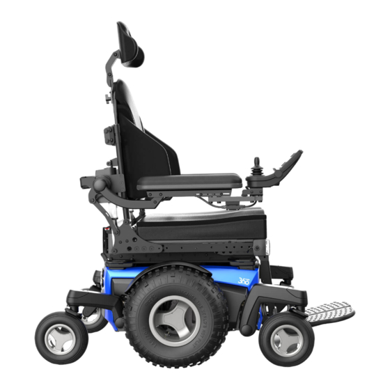
2.3 Serial number locations 2.4 Features Headrest Backrest Joystick Armrest Seat Unit Power Base Drive Wheels Footplate Rear Castors Front Castors Figure 2.2a Magic 360 Figure 2.3a Magic 360 Headrest Backrest Joystick Armrest Seat Unit Power Base Drive Wheels Footplate Rear Castors Front Castors Figure 2.3b Frontier V6... - Page 10 Headrest Backrest Joystick Armrest Seat Unit Power Base Drive Wheels Footplate Rear Castors Front Castors Figure 2.2d Frontier V4 FWD Figure 2.3d Frontier V4 FWD Headrest Backrest Joystick Armrest Seat Unit Power Base Footplate Drive Wheels Figure 2.2e Extreme X8 Figure 2.3e Extreme X8 Headrest Backrest...
-
Page 11: Indications For Use
Headrest Backrest Joystick Armrest Seat Unit Power Base Footplate Drive Wheels Figure 2.2g XT4 Figure 2.3g XT4 2.5 Indications for use EN 12182: 2012/ Class B Class C EN 12184: 2014 The Magic Mobility power wheelchairs are battery- operated devices with wheels. They are intended Magic 360 for medical purposes to provide mobility to persons Frontier V6 AT and Urban... -
Page 12: Important Definitions
2.9 Important definitions 2.12 Product safety notices and recalls This warning symbol refers to hazards or unsafe Be sure to let us know if you change your address or practices that may cause severe injury or death to contact details by emailing us at you or to other persons. -
Page 13: Safety
Safety Using your Magic Mobility product safely depends upon your own good judgement and/or common sense, as well as that of your caregiver, and/or health professional. Magic Mobility is not responsible for injuries and/or damage resulting from any person’s failure to follow the warnings, cautions and instructions in this Owner’s Manual or any of the documentation supplied with the powerchair. -
Page 14: Weight Limit
3.5 Weight limit Your powerchair has a maximum weight capacity. This limit is for the combined weight of you and your luggage (see Section 3.6 Bags and Backpacks). MODEL USER WEIGHT USER WEIGHT No seat elevator or tilt fitted Seat elevator or tilt fitted MAGIC 360 160 kg/350 lbs 160 kg/350 lbs FRONTIER V6 AT AND URBAN 182 kg/400 lbs... -
Page 15: Driving
• Stay in the middle of the ramp to reduce the risk of 3.11 Driving dropping a wheel off the side The speed and direction of the powerchair is generally controlled by the joystick: • Avoid potentially hazardous slopes and areas with •... -
Page 16: Driving At Night
Keep your eyes moving when you drive; scan the area 3.16 Driving at night ahead to look for obstacles. Lighting is designed to improve visibility while driving the chair in low-light or at night. It’s also intended to make the chair more visible to others. Be aware that your lights are not always visible to drivers or pedestrians, especially if viewing you from the sides of the chair. -
Page 17: Environmental Conditions
3.22 Environmental conditions 3.26 Alcohol, drugs and smoking Your powerchair is not designed for use in a heavy It’s strongly recommended that you don’t smoke rainstorm or in heavy snowy or icy conditions. Contact cigarettes while seated in your powerchair and with water or excessive moisture can cause an electrical that you stay away from naked flames, open fires and malfunction. -
Page 18: Op E R At I N G I N Str U Cti O N
Operating instructions Using your Magic Mobility product safely depends upon your own good judgement and/or common sense, as well as that of your caregiver, and/or health professional. Magic Mobility is not responsible for injuries and/or damage resulting from any person’s failure to follow the warnings, cautions and instructions in this Owner’s Manual or any of the documentation supplied with the powerchair. -
Page 19: Legrests
Swingaway and Power Elevating Swingaway - Press the 4.8 Legrests lever below the hanger to release the legrest allowing it Centre Mount and Centre Mount Power Elevating to rotate to the side of the wheelchair. The legrest can Legrest - The footplate can flip up to allow for easier be completely removed by lifting the hanger out of the transfers in and out of the wheelchair. -
Page 20: Fold Forward - If Fitted
4.9 Fold Forward - if fitted Fold Forward backs have a red release handle. Pull the handle to release the backrest and carefully lower it forwards. Figure 4.3d Extreme X8 Fold Forward height Figure 4.3e XT2 Fold Forward height Figure 4.3a Fold Forward grab handle Figure 4.3f XT4 Fold Forward height Figure 4.3b Magic 360 Fold Forward height Figure 4.3c Frontier V6 and V4 Fold Forward height... -
Page 21: Freewheel Mode - Pushing The Powerchair
4.10 Freewheel mode – pushing the powerchair There’s no braking on your powerchair when it’s in freewheel mode. Be sure to turn the power off before disengaging the motor brakes. Magic 360 – Two motor release levers are located o the rear of the powerchair (see Figures 4.4). To disengage the built-in or “running’... -
Page 22: On/Off Switch
Extreme X8 - Motor release levers are located at the rear of the powerchair (see Figures 4.6). Figure 4.6b Extreme X8 brake levers released Figure 4.6a Extreme X8 brake levers engaged XT2 & XT4 - Motor release levers are located at the rear of the powerchair (see Figures 4.7). Figure 4.7a XT2 &... -
Page 23: Seating
• Via programming it’s possible to reverse the direction 4.16 Shock absorber springs (Magic 360 only) of most power seating functions. Ensure that you The four shock absorber springs are set to factory default know which direction your seat will move before at time of manufacture. -
Page 24: Slope Sensor (Inclinometer) - If Fitted
• When the steering lock is engaged, only drive 4.17 Slope sensor (inclinometer) – if fitted the powerchair forwards and backwards The slope sensor option enables the chair to be aware of its backrest angle relative to the horizon. This includes • Attempting to drive the powerchair normally with the the accumulation of backrest recline, seating tilt and steering lock engaged could cause serious damage ground incline put together. -
Page 25: Lateral Supports
Swingaway legrest utilise kneepads that are removed 4.25 One Click Activator when the entire legrest is lifted out. The One Click Activator enables you to directly operate up to five actuator-based power functions, each with one simple click. When combined with a CJSM2 joystick, it has the added benefit of enabling you to change your power functions on-the-go, without having to stop your wheelchair. -
Page 26: Positioning Belts, Tie Downs And Transportation
Positioning belts, tie downs and transportation 5.1 Powerchair transportation in vehicles 5.4 Powerchair lifts and hoists (as cargo) Turn off your chair’s power when you are on a lift. If Always be sure your powerchair and its components are you fail to do so, you may touch the joystick by properly secured during transportation. - Page 27 Figure 5.2a Magic 360 lifting points Figure 5.2b Frontier V6 lifting points Figure 5.2c Frontier V4 lifting points Figure 5.2d Extreme X8 lifting points (sold separately) Figure 5.2e XT2 lifting points (sold separately) Figure 5.2f XT4 lifting points (sold separately) Powerchair Owner’s Manual magicmobility.com.au...
-
Page 28: Positioning Belts And Harnesses
5.6 Positioning belts and harnesses 5.7 Travelling in a vehicle while seated in your It’s the purchaser, therapist and healthcare professionals powerchair obligation to determine if a positioning belt is required Magic Mobility powerchairs comply with the to ensure user’s safe operation of the powerchair. requirements of ISO 7176-19 and, as such have been Positioning belts can be ordered through your Magic designed and tested for use only as a forward facing seat... - Page 29 Figure 5.4b Frontier V6 tie downs Figure 5.4a Magic 360 tie downs Figure 5.4c Frontier V4 tie downs Figure 5.4d Extreme X8 tie downs Figure 5.4e XT2 tie downs Figure 5.4f XT4 tie downs Powerchair Owner’s Manual magicmobility.com.au...
- Page 30 Occupant restraint instructions • Powerchair mounted lap belts or lap straps (postural or otherwise) should not be used as or relied upon for occupant restraint in a moving vehicle • Always use a three-point occupant restraint system to secure the occupant •...
- Page 31 Tests were conducted with a 102 kg or 76 kg • To reduce the potential of injury to vehicle crash test dummy (see section 11). Occupants occupants, powerchair mounted trays not with a higher weight are at increased risk specifically designed for crash safety should: during an accident.
-
Page 32: Retractable Docking Pin - If Fitted
5.8 Retractable docking pin – if fitted 5.9 Dahl docking system – if fitted The Magic 360 and Frontier V6 and V4 have an optional The DAHL Docking MK. II and the DAHL VarioDock crash tested retractable docking pin (see Figures systems have been tested with the Magic 360 and 5.7). -
Page 33: Bat T E Ri E S A Nd C H A Rg I
Batteries and charging • Batteries have a finite life and limits on the length 6.1 Electrical safety protection they supply and store energy. You can only charge Your powerchair has a fuse fitted to the battery circuit batteries a certain number of times before they will which provides a level of protection to the battery and its fail and no longer hold charge wiring in the event of a short circuit. -
Page 34: Battery Charging Procedure
6.5 Battery charging procedure 6.7 Achieving maximum range from your Batteries charge via a socket within the joystick module batteries (see Figure 6.2). When the battery charger is plugged in, Please note – always follow the run-in and charging the joystick recognises this, and chair driving is inhibited. procedures: The following procedure should be followed when •... -
Page 35: How Your Battery Gauge Works
LCD SCREEN BATTERY GAUGE Batteries are charged if the battery gauge displays red, yellow and green. If possible, charge batteries once the battery gauge displays only red and yellow. Charge batteries as soon as you can after the battery gauge displays only red: either steady or flashing slowly. -
Page 36: Ca R E A Nd M Ai N Te N An C
Care and maintenance Like any motorised vehicle, your powerchair requires routine maintenance checks. You can perform some of these checks yourself, but it’s recommended that your chair be inspected at a factory authorised service facility. Repairs or replacements, including batteries and tyres, should only be done using manufacturer-approved components to ensure optimal performance (see Section 7.20). -
Page 37: Magic 360 And Frontier V6/V4 Crossover Drive Wheels
7.3 Magic 360 and Frontier V6/V4 crossover drive wheels Maximum Tyre Description Magic Mobility Recommended Optimum Operating Pressures Pressure According to User Weight (lb) Tyre Capacity 5.30/4.50-6 38 psi 262 kPa 47-50 Nm User Weight (kg) 7.4 Magic 360 and XT2 urban grey drive wheels and Frontier V6/V4 urban drive wheels Maximum Tyre Description Magic Mobility Recommended Optimum Operating Pressures... -
Page 38: Frontier V6/V4 And Extreme X8 Off-Road Drive Wheels
7.6 Frontier V6/V4 and Extreme X8 off-road drive wheels Maximum Tyre Description Magic Mobility Recommended Optimum Operating Pressures Pressure According to User Weight (lb) Tyre Capacity 145/70-6 24 psi 165 kPa 47-50 Nm User Weight (kg) 7.7 Frontier V6/V4 castor wheels Frontier V6/V4 Castor Wheels Maximum Tyre Description... -
Page 39: Caring For Upholstery
Powerchair corrosion is commonly caused by: 7.11 Caring for upholstery Your powerchair upholstery can be cleaned with mild • Chips or scratches to paintwork caused by impact soap and water. It’s important to always avoid water with rocks or other hard objects transgressing into any electrical components. -
Page 40: Storage
environment to dry thoroughly. It may also help to blow • Repeat the test three times, pushing the joystick as much sand and/or salt off as possible. Never, ever backwards, left and right respectively hose down your powerchair. • Check tyre pressure is as per specification in Section 7.1 Preventative maintenance For regular beach use or in salty environments, we... -
Page 41: Annual Checks
Special local disposal or recycling regulations may 7.19 Annual checks apply. These must be considered when disposing It’s highly recommended to service your powerchair your powerchair. This may include cleaning or annually. Take your powerchair to your Magic Mobility decontaminating your powerchair prior to disposal. agent to ensure that correction function is maintained. -
Page 42: Joyst I C K Co Nt Ro
Joystick controls 8.1 LED joystick module LED JOYSTICK TROUBLESHOOTING If the problem persists after you have made the checks below, contact your authorised agent. *If motor swap has been enabled, then the left and right references will need transposing. Battery needs charging or there is a bad connection to the battery. Check the battery connection. -
Page 43: Locking The Control System
COMMON TROUBLESHOOTING CENTRE JOYSTICK Cause The most common cause of this trip is if joystick is deflected away from centre before and during the time it is switched on Solution Ensure that the joystick is centred and turn the CJSM2 on and off LOW BATTERY Cause Occurs when the CJSM2 detects that battery voltage has fallen below 16V... -
Page 44: Lect Rom Ag Ne Ti C I N T E R Fe R E N C E Emi
Electromagnetic Interference EMI CAUTION! The standard version of your powerchair has been tested on the applicable requirements with respect to electromagnetic radiation (EMC requirements). Regardless of these tests it can’t be excluded that electromagnetic radiation may influence the powerchair. For example: •... -
Page 45: 0 H Ow Doe S My P Ow E Rc H Ai R M E A S U Re Up
How does my powerchair measure up? One of the most common questions we receive is “how big is my powerchair?” and “how much does it weigh?” All Magic Mobility powerchairs are made to measure, just for you, so it’s not always a straightforward answer. But we’ll do our best to help. - Page 46 Technical specifications As the manufacture, Magic Mobility As the manufacture, Magic Mobility declares that the powered wheelchairs declares that the powered wheelchairs conform to the UK Medical Device conform to the Medical Device Regulation 2002. Regulation (2017/745). STANDARD DEFINITION / DESCRIPTION TEST DUMMY WEIGHT (KG) Frontier Frontier...
- Page 47 DESCRIPTION SPECIFICATIONS Magic 360 and Frontier 260 x 172 x 210 mm Maximum battery dimensions (l x w x h) Extreme X8 307 x 172 x 220 mm XT2 and XT4 333 x 171 x 237 mm Magic 360, Frontier and Extreme X8 70 Ah (C20) Battery capacity* Extreme X8...
- Page 48 Magic Mobility cannot provide technical specifications for non-Magic Mobility parts, nor can we guarantee performance according to the table below. If you can’t see what you need please contact your agent or Magic Mobility. MAGIC 360 Model designation of powerchair tested: Magic 360, with Power Lift, Power Tilt, Centre Power Legrest and Anti-Shear Rehab Back.
- Page 49 FRONTIER V6 AT AND URBAN Model designation of powerchair tested: Frontier V6 AT, with Power Lift, Power Tilt, Centre Legrest and MPS Backrest. Specifications for some common options are included. All measurements assume a seat depth of 460x460 mm (18x18”) and standard backrest heights. As each powerchair is built to order;...
- Page 50 FRONTIER V6 C73 (NOT AVAILABLE IN USA/EU) Model designation of powerchair tested: Frontier V6 C73, with Power Lift, Power Tilt, Centre Legrest and Rehab Backrest. Specifications for some common options are included. All measurements assume a seat depth of 460x460 mm (18x18”) and standard backrest heights. As each powerchair is built to order;...
- Page 51 FRONTIER V4 RWD Model designation of powerchair tested: Frontier V4 RWD with Roller, Power Lift, Power Tilt, Centre Legrest and MPS Backrest. Specifications for some common options are included. All measurements assume a seat depth of 460x460 mm (18x18”) and standard backrest heights. As each powerchair is built to order;...
- Page 52 FRONTIER V4 FWD Model designation of powerchair tested: Frontier V4 FWD, with Power Lift, Power Tilt, Centre Legrest and MPS Backrest. Specifications for some common options are included. All measurements assume a seat depth of 460x460 mm (18x18”) and standard backrest heights. As each powerchair is built to order;...
- Page 53 EXTREME X8 Model designation of powerchair tested: Extreme X8, with Power Lift, Power Tilt, Centre Legrest and Rehab Backrest. Specifications for some common options are included. All measurements assume a seat depth of 460x460 mm (18x18”) and standard backrest heights. As each powerchair is built to order;...
- Page 54 Model designation of powerchair tested: XT2, with Power Lift, Power Tilt, Centre Legrest and Rehab Backrest. Specifications for some common options are included. All measurements assume a seat depth of 460x460 mm (18x18”) and standard backrest heights. As each powerchair is built to order; variations to the information below are to be expected.
- Page 55 Model designation of powerchair tested: XT4, with Power Lift, Power Tilt, Centre Legrest and Rehab Backrest. Specifications for some common options are included. All measurements assume a seat depth of 460x460 mm (18x18”) and standard backrest heights. As each powerchair is built to order; variations to the information below are to be expected.
- Page 56 ALL MODELS Specifications for some common options are included. All measurements assume a seat depth of 460x460 mm (18x18”) and standard backrest heights. As each powerchair is built to order; variations to the information below are to be expected. DESCRIPTION MINIMUM MINIMUM MAXIMUM...
- Page 57 Fon +41 (0)31 958 3838 Telefon + 48 42 275 83 38 www.SunriseMedical.ch Fax + 48 42 209 35 23 pl@sunrisemedical.de Sunrise Medical (US) LLC www.Sunrise-Medical.pl 2842 N Business Park Avenue Fresno, CA 93727 Sunrise Medical S.A.S United States of America...
- Page 58 Tel +358 20 791 00 Tel +421800194984 info@berner.fi www.berner.fi Bauerfeind d.o.o. Goleška 20, HR - 10020 Sunrise Medical Japan Co., Ltd. Zagreb 1-456 Maguchi, Kazo City, Saitama prefecture, Hrvatska 349-1145, Japan Tel +385/1 6542 855 Tel + 81 480 31 6480 info@bauerfeind.hr...
Need help?
Do you have a question about the Magic Mobility MAGIC 360 and is the answer not in the manual?
Questions and answers