Advertisement
Quick Links
www.ti.com
EVM User's Guide: TAC5412Q15B5EVM-K TAC5411Q15B5EVM-K
TAA5412Q15B5EVM-K
TAx5x1xQ15B5EVM-K Evaluation Module
Description
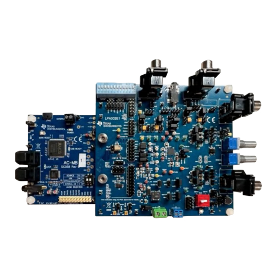
The TAx5x1xQ15B5EVM-K evaluation module (EVM)
allows the user to test the capabilities of
Texas Instruments' two-channel high-performance
ADC TAA5412-Q1, a two-channel TAC5412-Q1 or
TAC5411-Q1, a single-channel high-performance
codec. Other variants listed are also supported where
users can replace the U1 unit with the device of
interest. The evaluation module is paired with the
AC-MB, a flexible motherboard that provides power,
control, and digital audio data to the evaluation
module.
Get Started
1. Order the EVM from the TAx5x12 product folder.
2. Download the latest TAx5x12 data sheet.
3. Request access and download the PPC3 GUI
from the TAx5x12 product folder.
Features
•
Complete evaluation kit for the TAC5x12-Q1
(two-channel codec), TAC5x11-Q1 (single-channel
codec), or TAA5412-Q1 (two-channel ADC).
SLAAEC6A – OCTOBER 2023 – REVISED JANUARY 2024
Submit Document Feedback
•
High-performance mono/stereo codec dynamic
range: 120 dB DAC and 110 dB ADC or standard
performance 106 dB DAC and 102 dB ADC
•
On-board microphones provided for voice
recording testing
•
Direct access to digital audio signals and control
interface for simple end-system integration
•
USB connection to PC provides power, control,
and streaming audio data for easy evaluation
•
On-board diagnostic scenarios for analog audio
input
Applications
•
Emergency E-Call
•
Telematics control unit
•
Automotive active noise cancellation
•
Automotive head units
Copyright © 2024 Texas Instruments Incorporated
TAx5x1xQ15B5EVM-K Evaluation Module
Description
1
Advertisement

Related Manuals for Texas Instruments TAC5412Q15B5EVM-K


Summary of Contents for Texas Instruments TAC5412Q15B5EVM-K
- Page 1 Description EVM User's Guide: TAC5412Q15B5EVM-K TAC5411Q15B5EVM-K TAA5412Q15B5EVM-K TAx5x1xQ15B5EVM-K Evaluation Module • High-performance mono/stereo codec dynamic Description range: 120 dB DAC and 110 dB ADC or standard The TAx5x1xQ15B5EVM-K evaluation module (EVM) performance 106 dB DAC and 102 dB ADC allows the user to test the capabilities of •...
-
Page 2: Kit Contents
TAx5x1x-Q1 family of devices. This family includes the devices shown in Table 1-1 with differences in performance and function noted. This user's guide describes the functionality of the TAC5412Q15B5EVM-K, TAC5411Q15B5EVM, or TAA5412Q15B5EVM-K evaluation kit. Table 1-1. TAx5x1x-Q1 Family Device... -
Page 3: Hardware Overview
Test Points SCLK /POR Power-On Reset /SS 1-2 /RESET /RESET /RESET_SW Main AC_MB_EVM_Connector Rest AC_MB Figure 2-2. TAx5x1xQ1 EVM Block Diagram SLAAEC6A – OCTOBER 2023 – REVISED JANUARY 2024 TAx5x1xQ15B5EVM-K Evaluation Module Submit Document Feedback Copyright © 2024 Texas Instruments Incorporated... - Page 4 32-bit frame size, 48-kHz sampling rate, BCLK and FSYNC ratio of 256, and the format is time-division multiplexing (TDM). TAx5x1xQ15B5EVM-K Evaluation Module SLAAEC6A – OCTOBER 2023 – REVISED JANUARY 2024 Submit Document Feedback Copyright © 2024 Texas Instruments Incorporated...
- Page 5 (DAC) is connected to the AC-MB, providing an analog input for quick evaluation. In auxiliary analog audio mode, the audio serial interface format is fixed to a 24-bit, 48-kHz, I2S mode. SLAAEC6A – OCTOBER 2023 – REVISED JANUARY 2024 TAx5x1xQ15B5EVM-K Evaluation Module Submit Document Feedback Copyright © 2024 Texas Instruments Incorporated...
- Page 6 Odd-numbered pins are signal-carrying; even- numbered pins are connected to ground. Figure 2-7. AC-MB Connection with External Audio Serial Interface TAx5x1xQ15B5EVM-K Evaluation Module SLAAEC6A – OCTOBER 2023 – REVISED JANUARY 2024 Submit Document Feedback Copyright © 2024 Texas Instruments Incorporated...
- Page 7 LDOs are correct. The USB READY LED indicates a successful USB communication between the AC-MB and the host computer. SLAAEC6A – OCTOBER 2023 – REVISED JANUARY 2024 TAx5x1xQ15B5EVM-K Evaluation Module Submit Document Feedback Copyright © 2024 Texas Instruments Incorporated...
- Page 8 AC or DC-coupled modes. Jumper configuration details can be found in Table 2-1. TAx5x1xQ15B5EVM-K Evaluation Module SLAAEC6A – OCTOBER 2023 – REVISED JANUARY 2024 Submit Document Feedback Copyright © 2024 Texas Instruments Incorporated...
- Page 9 J4, J5, J8, J11, J6, J15, J16 Refer to B0_P0_R80, Condenser J12 (1-2), J20, J21 Microphone data B0_P1_R115 Microphone sheet (ECM) Differential, AC-coupled SLAAEC6A – OCTOBER 2023 – REVISED JANUARY 2024 TAx5x1xQ15B5EVM-K Evaluation Module Submit Document Feedback Copyright © 2024 Texas Instruments Incorporated...
- Page 10 Refer to the B0_P0_R85, Analog MEMS J23, J8 (DUT Microphone data B0_P1_R115 microphone, DC- MICBIAS is not sheet. coupled used) TAx5x1xQ15B5EVM-K Evaluation Module SLAAEC6A – OCTOBER 2023 – REVISED JANUARY 2024 Submit Document Feedback Copyright © 2024 Texas Instruments Incorporated...
- Page 11 The TAx5x1x-Q1 evaluation module has several output configuration options and offers flexibility to allow the user to evaluate the device with different load conditions and configurations. The different configurations are highlighted in this section. SLAAEC6A – OCTOBER 2023 – REVISED JANUARY 2024 TAx5x1xQ15B5EVM-K Evaluation Module Submit Document Feedback Copyright © 2024 Texas Instruments Incorporated...
- Page 12 10 kΩ 0.4 W B0_P0_R101 Figure 2-13. TAC5x12-Q1 Analog Output Connections For TAC5411-Q1 or TAC5311-Q1, OUT2 components are not populated. TAx5x1xQ15B5EVM-K Evaluation Module SLAAEC6A – OCTOBER 2023 – REVISED JANUARY 2024 Submit Document Feedback Copyright © 2024 Texas Instruments Incorporated...
- Page 13 MICBIAS test. If using a single-ended input for the test channel, only connect INxP. Figure 2-15. Short to MICBIAS Diagnostic Test Setup SLAAEC6A – OCTOBER 2023 – REVISED JANUARY 2024 TAx5x1xQ15B5EVM-K Evaluation Module Submit Document Feedback Copyright © 2024 Texas Instruments Incorporated...
- Page 14 2.2.3.3 Shorted Input Pins Setup Shorted input diagnostic testing can be performed for differential inputs only. Figure 2-18. Short to Input Diagnostic Test Setup TAx5x1xQ15B5EVM-K Evaluation Module SLAAEC6A – OCTOBER 2023 – REVISED JANUARY 2024 Submit Document Feedback Copyright © 2024 Texas Instruments Incorporated...
- Page 15 GPIO1 can be configured as either the WCLK, BCLK, DIN, or DOUT in the controller or peripheral mode, as shown in Figure 2-20. Figure 2-20. GPIO1 Configuration SLAAEC6A – OCTOBER 2023 – REVISED JANUARY 2024 TAx5x1xQ15B5EVM-K Evaluation Module Submit Document Feedback Copyright © 2024 Texas Instruments Incorporated...
- Page 16 (ASI2). In Audio Serial Interface, GPI1A can be configured as either the WCLK, BCLK, or DIN in peripheral mode, as shown in Figure 2-22. Figure 2-22. GPI1A Configuration TAx5x1xQ15B5EVM-K Evaluation Module SLAAEC6A – OCTOBER 2023 – REVISED JANUARY 2024 Submit Document Feedback Copyright © 2024 Texas Instruments Incorporated...
- Page 17 (pull-up to AVDD). Header J73 needs to be populated on pin 1-2. Device Address (7-bit Device Address (8-bit ADDRA Level Addressing) Addressing) AVDD 0x51 0xA2 0x50 0xA0 SLAAEC6A – OCTOBER 2023 – REVISED JANUARY 2024 TAx5x1xQ15B5EVM-K Evaluation Module Submit Document Feedback Copyright © 2024 Texas Instruments Incorporated...
- Page 18 SASI with the external audio instrument, remove the jumpers on header J43 and place jumper on header J67 pin 2-3, as shown in Figure 2-25. Figure 2-25. External Audio Serial Interface Connection TAx5x1xQ15B5EVM-K Evaluation Module SLAAEC6A – OCTOBER 2023 – REVISED JANUARY 2024 Submit Document Feedback Copyright © 2024 Texas Instruments Incorporated...
- Page 19 Open the PPC3 installer and follow the instructions in the setup wizard. 3.2.1 USB Audio Setup Note When using the USB audio interface, the Texas Instruments USB audio device control panel, shown in Figure 3-2, opens with the input setting configured for eight channels, 32 bits. For USB audio, 32-bit mode must also be used on the EVM.
- Page 20 GUI values; either selection works for the initial setup. Figure 3-5. Update GUI-Device TAx5x1xQ15B5EVM-K Evaluation Module SLAAEC6A – OCTOBER 2023 – REVISED JANUARY 2024 Submit Document Feedback Copyright © 2024 Texas Instruments Incorporated...
- Page 21 Users must first configure the device and then activate the PPC3. Once activated, some controls are grayed out until the ACTIVE button is deactivated. Figure 3-8. Activate GUI SLAAEC6A – OCTOBER 2023 – REVISED JANUARY 2024 TAx5x1xQ15B5EVM-K Evaluation Module Submit Document Feedback Copyright © 2024 Texas Instruments Incorporated...
-
Page 22: Software Overview
3-9, contains all of the settings used to configure and program the TAx5x1x-Q1 EVM. This view has tabs associated to the device configuration. Figure 3-9. Configuration View TAx5x1xQ15B5EVM-K Evaluation Module SLAAEC6A – OCTOBER 2023 – REVISED JANUARY 2024 Submit Document Feedback Copyright © 2024 Texas Instruments Incorporated... -
Page 23: Device Config Tab
Input channel 3 and channel 4 are associated with the PDM input channels. Figure 3-10. Device Config Tab SLAAEC6A – OCTOBER 2023 – REVISED JANUARY 2024 TAx5x1xQ15B5EVM-K Evaluation Module Submit Document Feedback Copyright © 2024 Texas Instruments Incorporated... - Page 24 Input channel 3 and channel 4 are associated with Digital Microphone inputs. For PDM input, several PDM clock selections are available with the associated data and clock triggering in this record config tab. TAx5x1xQ15B5EVM-K Evaluation Module SLAAEC6A – OCTOBER 2023 – REVISED JANUARY 2024 Submit Document Feedback Copyright © 2024 Texas Instruments Incorporated...
- Page 25 Software Figure 3-12. PDM Record Config Tab SLAAEC6A – OCTOBER 2023 – REVISED JANUARY 2024 TAx5x1xQ15B5EVM-K Evaluation Module Submit Document Feedback Copyright © 2024 Texas Instruments Incorporated...
- Page 26 Depending on the selection, some of the controls are grayed out, which means the controls are not available for configuration. Figure 3-13. Playback Config TAx5x1xQ15B5EVM-K Evaluation Module SLAAEC6A – OCTOBER 2023 – REVISED JANUARY 2024 Submit Document Feedback Copyright © 2024 Texas Instruments Incorporated...
- Page 27 3.3.2.4.1 Configuring Primary Audio Serial Bus Figure 3-14. Primary Audio Serial Bus - Page 1 Figure 3-15. Primary Audio Serial Bus TX - Page 2 SLAAEC6A – OCTOBER 2023 – REVISED JANUARY 2024 TAx5x1xQ15B5EVM-K Evaluation Module Submit Document Feedback Copyright © 2024 Texas Instruments Incorporated...
- Page 28 Software www.ti.com Figure 3-16. Primary Audio Serial Bus RX - Page 3 TAx5x1xQ15B5EVM-K Evaluation Module SLAAEC6A – OCTOBER 2023 – REVISED JANUARY 2024 Submit Document Feedback Copyright © 2024 Texas Instruments Incorporated...
- Page 29 Figure 3-17. Secondary Audio Serial Bus Page 1 Figure 3-18. Secondary Audio Serial Bus TX - Page 2 SLAAEC6A – OCTOBER 2023 – REVISED JANUARY 2024 TAx5x1xQ15B5EVM-K Evaluation Module Submit Document Feedback Copyright © 2024 Texas Instruments Incorporated...
- Page 30 2-channel I2S output to a USB audio at 16 bits and 48 kHz. Figure 3-20. Configuring I2S Example TAx5x1xQ15B5EVM-K Evaluation Module SLAAEC6A – OCTOBER 2023 – REVISED JANUARY 2024 Submit Document Feedback Copyright © 2024 Texas Instruments Incorporated...
- Page 31 On the right side is the Interrupt selection, which has the settings as well as flag update/status of the respective interrupt. Figure 3-21. GPIO and Interrupts Tab SLAAEC6A – OCTOBER 2023 – REVISED JANUARY 2024 TAx5x1xQ15B5EVM-K Evaluation Module Submit Document Feedback Copyright © 2024 Texas Instruments Incorporated...
-
Page 32: Advanced Tabs
Some diagnostic settings are available on the left hand side if needed. Figure 3-23. Diagnostic Tab TAx5x1xQ15B5EVM-K Evaluation Module SLAAEC6A – OCTOBER 2023 – REVISED JANUARY 2024 Submit Document Feedback Copyright © 2024 Texas Instruments Incorporated... - Page 33 Read button. If no EVM is connected, PPC3 assumes sampling rate of 48 kHz for all biquad calculations. Figure 3-24. Programmable ADC Biquads Tab Figure 3-25. Programmable DAC Biquads Tab SLAAEC6A – OCTOBER 2023 – REVISED JANUARY 2024 TAx5x1xQ15B5EVM-K Evaluation Module Submit Document Feedback Copyright © 2024 Texas Instruments Incorporated...
- Page 34 The level is ratio of the mixer full-scale and user can enter in the cell provided. Besides the external inputs, there are beep and chirp generators that user can mix in DAC mixer as well. Figure 3-27. Mixer DAC Tab TAx5x1xQ15B5EVM-K Evaluation Module SLAAEC6A – OCTOBER 2023 – REVISED JANUARY 2024 Submit Document Feedback Copyright © 2024 Texas Instruments Incorporated...
- Page 35 3.3.2.6.4 Limiter Tab Various device limiters like brown out and temperature are available in this tab. Figure 3-28. Limiter Tab SLAAEC6A – OCTOBER 2023 – REVISED JANUARY 2024 TAx5x1xQ15B5EVM-K Evaluation Module Submit Document Feedback Copyright © 2024 Texas Instruments Incorporated...
- Page 36 The register map view provides a view of page 0, page 1, and page 3 of the register map. Figure 3-30. Register Map View TAx5x1xQ15B5EVM-K Evaluation Module SLAAEC6A – OCTOBER 2023 – REVISED JANUARY 2024 Submit Document Feedback Copyright © 2024 Texas Instruments Incorporated...
-
Page 37: Preset Configuration
To load an existing file or to manually write or read I2C transaction, click on the I/O button to open the input/ output window. Figure 3-32. I2C Monitor Window SLAAEC6A – OCTOBER 2023 – REVISED JANUARY 2024 TAx5x1xQ15B5EVM-K Evaluation Module Submit Document Feedback Copyright © 2024 Texas Instruments Incorporated... - Page 38 Software www.ti.com Figure 3-33. I2C Monitor I/O Window TAx5x1xQ15B5EVM-K Evaluation Module SLAAEC6A – OCTOBER 2023 – REVISED JANUARY 2024 Submit Document Feedback Copyright © 2024 Texas Instruments Incorporated...
-
Page 39: Configuration Examples
76 c0 # Enable Input Ch1 and Ch2, disable output channels w a0 78 a0 # Power up ADC and MICBIAS SLAAEC6A – OCTOBER 2023 – REVISED JANUARY 2024 TAx5x1xQ15B5EVM-K Evaluation Module Submit Document Feedback Copyright © 2024 Texas Instruments Incorporated... - Page 40 76 c0 # Enable input Chl and Ch2, disable output channels w a0 78 80 # Power up ADC TAx5x1xQ15B5EVM-K Evaluation Module SLAAEC6A – OCTOBER 2023 – REVISED JANUARY 2024 Submit Document Feedback Copyright © 2024 Texas Instruments Incorporated...
- Page 41 76 c0 # Enable Input Ch1 and Ch2, disable output channels w a0 78 a0 # Power up ADC and MICBIAS SLAAEC6A – OCTOBER 2023 – REVISED JANUARY 2024 TAx5x1xQ15B5EVM-K Evaluation Module Submit Document Feedback Copyright © 2024 Texas Instruments Incorporated...
- Page 42 # Disable all input channels and enable output channel 1 and 2 w a0 78 40 # Power up all DAC channel TAx5x1xQ15B5EVM-K Evaluation Module SLAAEC6A – OCTOBER 2023 – REVISED JANUARY 2024 Submit Document Feedback Copyright © 2024 Texas Instruments Incorporated...
- Page 43 # Disable all input channels and enable output channel 1 and 2 w a0 78 40 # Power up all DAC channels SLAAEC6A – OCTOBER 2023 – REVISED JANUARY 2024 TAx5x1xQ15B5EVM-K Evaluation Module Submit Document Feedback Copyright © 2024 Texas Instruments Incorporated...
- Page 44 76 c0 # Enable ADC channel 1 and channel 2 w a0 78 a0 # Power up ADC and MICBIAS TAx5x1xQ15B5EVM-K Evaluation Module SLAAEC6A – OCTOBER 2023 – REVISED JANUARY 2024 Submit Document Feedback Copyright © 2024 Texas Instruments Incorporated...
- Page 45 This section provides the schematics, layout examples, and bill of materials (BOM) for each TAC541x-Q1 EVM variant. 4.1 TAC5412-Q1 EVM Schematic Figure 4-1. TAC5412-Q1 EVM Main DUT Schematic SLAAEC6A – OCTOBER 2023 – REVISED JANUARY 2024 TAx5x1xQ15B5EVM-K Evaluation Module Submit Document Feedback Copyright © 2024 Texas Instruments Incorporated...
- Page 46 Hardware Design Files www.ti.com Figure 4-2. TAC5412-Q1 EVM Connectors and Supporting Circuitry Schematic TAx5x1xQ15B5EVM-K Evaluation Module SLAAEC6A – OCTOBER 2023 – REVISED JANUARY 2024 Submit Document Feedback Copyright © 2024 Texas Instruments Incorporated...
- Page 47 Hardware Design Files 4.2 TAC5411-Q1 EVM Schematic Figure 4-3. TAC5411-Q1 EVM Main DUT Schematic SLAAEC6A – OCTOBER 2023 – REVISED JANUARY 2024 TAx5x1xQ15B5EVM-K Evaluation Module Submit Document Feedback Copyright © 2024 Texas Instruments Incorporated...
- Page 48 Hardware Design Files www.ti.com Figure 4-4. TAC5411-Q1 EVM Connectors and Supporting Circuitry Schematic TAx5x1xQ15B5EVM-K Evaluation Module SLAAEC6A – OCTOBER 2023 – REVISED JANUARY 2024 Submit Document Feedback Copyright © 2024 Texas Instruments Incorporated...
- Page 49 Figure 4-5. TAC541x-Q1 EVM Top Silkscreen Figure 4-7. TAC541x-Q1 EVM Power Layer 1 Figure 4-8. TAC541x-Q1 EVM Power Layer 2 SLAAEC6A – OCTOBER 2023 – REVISED JANUARY 2024 TAx5x1xQ15B5EVM-K Evaluation Module Submit Document Feedback Copyright © 2024 Texas Instruments Incorporated...
- Page 50 Figure 4-10. TAC541x-Q1 EVM Ground Layer 2 Figure 4-11. TAC541x-Q1 EVM Signal Layer 1 Figure 4-12. TAC541x-Q1 EVM Signal Layer 2 TAx5x1xQ15B5EVM-K Evaluation Module SLAAEC6A – OCTOBER 2023 – REVISED JANUARY 2024 Submit Document Feedback Copyright © 2024 Texas Instruments Incorporated...
- Page 51 Hardware Design Files Figure 4-14. TAC541x-Q1 EVM Bottom Silkscreen Figure 4-13. TAC541x-Q1 EVM Bottom Layer SLAAEC6A – OCTOBER 2023 – REVISED JANUARY 2024 TAx5x1xQ15B5EVM-K Evaluation Module Submit Document Feedback Copyright © 2024 Texas Instruments Incorporated...
- Page 52 CAP, CERM, 0.1 uF, 16 V, +/- 10%, C32, C33, C36, 0.1uF 0402 8.85012E+11 Wurth Elektronik X7R, 0402 C37, C38, C39, TAx5x1xQ15B5EVM-K Evaluation Module SLAAEC6A – OCTOBER 2023 – REVISED JANUARY 2024 Submit Document Feedback Copyright © 2024 Texas Instruments Incorporated...
- Page 53 Electronics GND7, GND8, GND9, GND10 GPI1A, GPI2A, Yellow Miniature Keystone Test Point, Miniature, Yellow, TH 5004 GPIO1, GPO1A Testpoint Electronics SLAAEC6A – OCTOBER 2023 – REVISED JANUARY 2024 TAx5x1xQ15B5EVM-K Evaluation Module Submit Document Feedback Copyright © 2024 Texas Instruments Incorporated...
- Page 54 Connector, Header, High Speed, 20 QTE-020-01-X-D-A QTE-020-01-L-D-A Samtec pairs, SMT Header, 100 mil, 10 x 2, Gold, TH 10 x 2 Header TSW-110-07-G-D Samtec TAx5x1xQ15B5EVM-K Evaluation Module SLAAEC6A – OCTOBER 2023 – REVISED JANUARY 2024 Submit Document Feedback Copyright © 2024 Texas Instruments Incorporated...
- Page 55 R16, R38, R39, 0603 PMR03EZPJ000 Rohm Grade 0, 0603 R21, R24, R27, RES, 16.0, 1%, 0.5 W, 0805 0805 ERJ-P06F16R0V Panasonic SLAAEC6A – OCTOBER 2023 – REVISED JANUARY 2024 TAx5x1xQ15B5EVM-K Evaluation Module Submit Document Feedback Copyright © 2024 Texas Instruments Incorporated...
- Page 56 Resistor 0402 (1005 Metric) 0402 RC0402JR-1310KL Yageo Moisture Resistant Thick Film Trimmer Potentiometer, 20 k ohm, Trimmer, PVG5A203C03R00 Bourns 0.25 W, SMD 4.8,3.9x5.1mm TAx5x1xQ15B5EVM-K Evaluation Module SLAAEC6A – OCTOBER 2023 – REVISED JANUARY 2024 Submit Document Feedback Copyright © 2024 Texas Instruments Incorporated...
- Page 57 Switch, Tactile, SPST-NO, 0.05 A, Switch, 4.4x2x2.9 TL1015AF160QG E-Switch 12 V, SMT Switch, DPDT, 0.15 A, 30 VDC, TH 9.65x9.65mm 76STD01T Grayhill SLAAEC6A – OCTOBER 2023 – REVISED JANUARY 2024 TAx5x1xQ15B5EVM-K Evaluation Module Submit Document Feedback Copyright © 2024 Texas Instruments Incorporated...
- Page 58 Header, 100mil, 2x1, Gold, TH 2x1 Header TSW-102-07-G-S Samtec R17, R18, R19, RES, 100, 1%, 0.1 W, 0603 0603 RC0603FR-07100RL Yageo TAx5x1xQ15B5EVM-K Evaluation Module SLAAEC6A – OCTOBER 2023 – REVISED JANUARY 2024 Submit Document Feedback Copyright © 2024 Texas Instruments Incorporated...
- Page 59 Q200 Grade 0, 0805 RES, 1.50 k, 1%, 0.063 W, AEC- Stackpole R54, R55 1.50k 0402 RMCF0402FT1K50 Q200 Grade 0, 0402 Electronics Inc SLAAEC6A – OCTOBER 2023 – REVISED JANUARY 2024 TAx5x1xQ15B5EVM-K Evaluation Module Submit Document Feedback Copyright © 2024 Texas Instruments Incorporated...
- Page 60 C32, C33, C37, X7R, 0402 C38, C39, C40 CAP, CERM, 2.2 uF, 16 V, +/- 10%, 2.2uF 0805 C2012X7R1C225K125AB X7R, 0805 TAx5x1xQ15B5EVM-K Evaluation Module SLAAEC6A – OCTOBER 2023 – REVISED JANUARY 2024 Submit Document Feedback Copyright © 2024 Texas Instruments Incorporated...
- Page 61 Small nylon hex nut, 0.10 thick with Hex Nut,4-40 H1, H2 a 0.250 outside diameter and a 4-40 Thread, 250" Head 9605 Keystone threading SLAAEC6A – OCTOBER 2023 – REVISED JANUARY 2024 TAx5x1xQ15B5EVM-K Evaluation Module Submit Document Feedback Copyright © 2024 Texas Instruments Incorporated...
- Page 62 J43, J59, J60 Header, 2.54mm, 2x2, Gold, TH PBC02DAAN 2x2, TH Solutions Header, 100mil, 7x2, Gold, TH 7x2 Header TSW-107-07-G-D Samtec TAx5x1xQ15B5EVM-K Evaluation Module SLAAEC6A – OCTOBER 2023 – REVISED JANUARY 2024 Submit Document Feedback Copyright © 2024 Texas Instruments Incorporated...
- Page 63 RES SMD 10K OHM 5% 0.4W 0805 0805 ESR10EZPJ103 Semiconductor RES, 2.2 k, 5%, 0.063 W, AEC-Q200 2.2k 0402 CRCW04022K20JNED Vishay-Dale Grade 0, 0402 SLAAEC6A – OCTOBER 2023 – REVISED JANUARY 2024 TAx5x1xQ15B5EVM-K Evaluation Module Submit Document Feedback Copyright © 2024 Texas Instruments Incorporated...
- Page 64 20% 1/20W/1/40W PC Pins Thru- PTD902-2015F-B104 Bourns 24MM65 Hole Trimmer Potentiometer, 20 k ohm, Trimmer, PVG5A203C03R00 Bourns 0.25 W, SMD 4.8,3.9x5.1mm TAx5x1xQ15B5EVM-K Evaluation Module SLAAEC6A – OCTOBER 2023 – REVISED JANUARY 2024 Submit Document Feedback Copyright © 2024 Texas Instruments Incorporated...
- Page 65 24LC512-I/ST Microchip 8TSSOP 500-mA, low-IQ, high-PSRR, dual- Texas channel low-dropout (LDO) voltage WSON10 TLV751180330PDSQR Instruments regulator 10-WSON -40 to 125 SLAAEC6A – OCTOBER 2023 – REVISED JANUARY 2024 TAx5x1xQ15B5EVM-K Evaluation Module Submit Document Feedback Copyright © 2024 Texas Instruments Incorporated...
- Page 66 Header, 100mil, 2x1, Gold, TH 2x1 Header TSW-102-07-G-S Samtec J37, J53 J14, J57 Header, 100mil, 3x1, Gold, TH 3x1 Header TSW-103-07-G-S Samtec TAx5x1xQ15B5EVM-K Evaluation Module SLAAEC6A – OCTOBER 2023 – REVISED JANUARY 2024 Submit Document Feedback Copyright © 2024 Texas Instruments Incorporated...
- Page 67 Moisture Resistant Thick Film RES, 1.50 k, 1%, 0.063 W, AEC- Stackpole R54, R55 1.50k 0402 RMCF0402FT1K50 Q200 Grade 0, 0402 Electronics Inc SLAAEC6A – OCTOBER 2023 – REVISED JANUARY 2024 TAx5x1xQ15B5EVM-K Evaluation Module Submit Document Feedback Copyright © 2024 Texas Instruments Incorporated...
- Page 68 7 Hz - 36 kHz Analog Microphone MEMS (Silicon) 2.3 V - 3.6 V SPH8878LR5H-1 Knowles SPH1878LR5H-C Knowles Omnidirectional (-44dB ± 0.5dB SPL) Solder Pads TAx5x1xQ15B5EVM-K Evaluation Module SLAAEC6A – OCTOBER 2023 – REVISED JANUARY 2024 Submit Document Feedback Copyright © 2024 Texas Instruments Incorporated...
-
Page 69: Additional Information
5 Additional Information 5.1 Trademarks PurePath ™ is a trademark of Texas Instruments. All trademarks are the property of their respective owners. 5.2 Cable References The following cables can be used for evaluation with external audio instruments like Audio Precision: •... - Page 70 STANDARD TERMS FOR EVALUATION MODULES Delivery: TI delivers TI evaluation boards, kits, or modules, including any accompanying demonstration software, components, and/or documentation which may be provided together or separately (collectively, an “EVM” or “EVMs”) to the User (“User”) in accordance with the terms set forth herein.
- Page 71 www.ti.com Regulatory Notices: 3.1 United States 3.1.1 Notice applicable to EVMs not FCC-Approved: FCC NOTICE: This kit is designed to allow product developers to evaluate electronic components, circuitry, or software associated with the kit to determine whether to incorporate such items in a finished product and software developers to write software applications for use with the end product.
- Page 72 www.ti.com Concernant les EVMs avec antennes détachables Conformément à la réglementation d'Industrie Canada, le présent émetteur radio peut fonctionner avec une antenne d'un type et d'un gain maximal (ou inférieur) approuvé pour l'émetteur par Industrie Canada. Dans le but de réduire les risques de brouillage radioélectrique à...
- Page 73 www.ti.com EVM Use Restrictions and Warnings: 4.1 EVMS ARE NOT FOR USE IN FUNCTIONAL SAFETY AND/OR SAFETY CRITICAL EVALUATIONS, INCLUDING BUT NOT LIMITED TO EVALUATIONS OF LIFE SUPPORT APPLICATIONS. 4.2 User must read and apply the user guide and other available documentation provided by TI regarding the EVM prior to handling or using the EVM, including without limitation any warning or restriction notices.
- Page 74 Notwithstanding the foregoing, any judgment may be enforced in any United States or foreign court, and TI may seek injunctive relief in any United States or foreign court. Mailing Address: Texas Instruments, Post Office Box 655303, Dallas, Texas 75265 Copyright © 2023, Texas Instruments Incorporated...
- Page 75 TI products. TI’s provision of these resources does not expand or otherwise alter TI’s applicable warranties or warranty disclaimers for TI products. TI objects to and rejects any additional or different terms you may have proposed. IMPORTANT NOTICE Mailing Address: Texas Instruments, Post Office Box 655303, Dallas, Texas 75265 Copyright © 2024, Texas Instruments Incorporated...
Need help?
Do you have a question about the TAC5412Q15B5EVM-K and is the answer not in the manual?
Questions and answers