Table of Contents
Advertisement
Advertisement
Table of Contents
Troubleshooting

Related Manuals for ResMed AirSense 11 Series


Summary of Contents for ResMed AirSense 11 Series
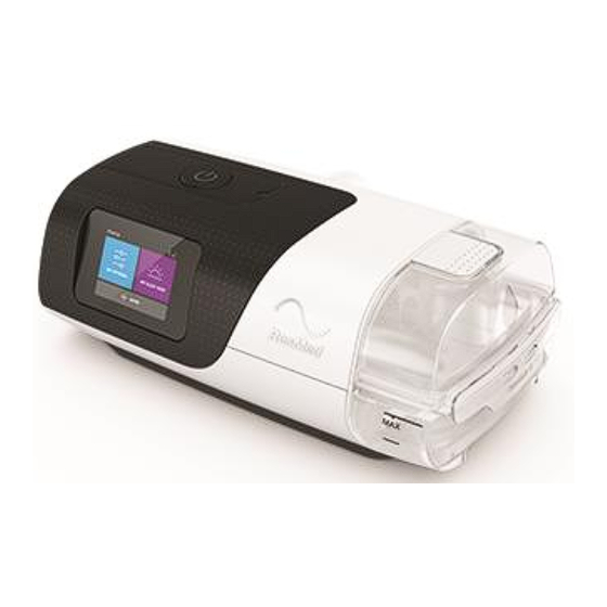
- Page 1 AirSense 11 Series Service Manual 398011/2 2022-03...
-
Page 2: Table Of Contents
Humidifier ............................7 Sensors ............................8 Power management ........................8 Test procedures ........................... 9 Service flow chart ........................9 Using ResMed Service Connect (RSC) ....................10 Equipment required ......................... 11 Software ............................11 Test equipment ..........................11 General inspection procedures .................... 12 Clean the device and replace filter .................. - Page 3 AirSense 11 service manual Reassembly..........................37 Blower assembly installation ......................37 Chassis assembly installation ......................40 Main PCB installation ........................43 LCD assembly ..........................46 Top case installation ........................47 Fascia installation .......................... 48 Side panel installation ........................49 Name plaque installation ......................49 SD insert installation ........................
-
Page 4: How To Use This Manual
Replacement parts – Shows pictures and part numbers of all the product spare parts and subassemblies available from ResMed. Troubleshooting guide – Provides a comprehensive list of device error messages, along with possible causes and fixes. -
Page 5: Introduction
use the correct Operator safety and static precautions described in this manual Use only ResMed approved parts and never use parts that have failed, show excessive wear, have been contaminated, or are ineffective for their intended use. Note: Technical specifications for each device are available in the device User and Clinical Guides. -
Page 6: Airsense 11 Exploded View
AirSense 11 service manual AirSense 11 exploded view 398011/2... -
Page 7: System Description
AirSense 11 service manual System description The following block diagram provides a simplified view of the AirSense 11 system. The AirSense 11 comprises the following subassemblies: Main Printed Circuit Board Assembly (PCB) LCD module Pneumatic block Humidifier Main Printed Circuit Board Assembly The Main PCB assembly includes the main controller circuits, the DC connector, ClimateLine... -
Page 8: Lcd Module
AirSense 11 service manual LCD module The LCD module is also a touch screen which is used to operate the device. It allows clinicians and patients to access, view and change therapy and device settings. There are two actions to navigate through the touch screen: Flick: Flick up or down the screen to view menu options. -
Page 9: Sensors
Pressure sensor Internally located at device outlet -5 – 45 cm H Power management The AirSense 11 series can be used with two different power sources: AC mains power External DC power supply (e.g., car 12V power outlet) -
Page 10: Test Procedures
AirSense 11 service manual Test procedures Testing of the device is required at multiple stages throughout the device service process. The following flow chart outlines the service process, and the use of ResMed Service Connect within this process. Service flow chart... -
Page 11: Using Resmed Service Connect (Rsc)
AirSense 11 service manual Using ResMed Service Connect (RSC) As detailed in the flow chart on the previous page, the different tabs available in ResMed Service Connect can be used for each stage. The details of when the tabs are used in the service process are as follows:... -
Page 12: Equipment Required
Guide (#198161) Data export tool Both RSC and the data export tool are available under the Service software tab on the AirSense 11 pages of the Support website (support.resmed.com/en-us/). Test equipment A computer running Windows 10 (64 bit) ... -
Page 13: General Inspection Procedures
1. Open the filter cover and remove the air filter. 2. Place the new air filter onto the cover. 3. Close the cover. Use only genuine ResMed spare parts, because the filter affects the flow CAUTION characteristics of the flow generator, which in turn affects the pressure supplied to the patient. -
Page 14: Download Device Logs
AirSense 11 service manual Download device logs 1. Connect the Gridconnect adapter to the PC and the CAN cable. 2. Connect the CAN cable to both the device and the power cord. 3. Connect the power cord to the power outlet. Gridconnect adapter Power cord (to mains power) - Page 15 AirSense 11 service manual 8. The export tool will then indicate the COM port has been selected. 9. Click on the Extract button. Note: When the mouse cursor hovers over the Extract button, the button will he highlighted and the text description will appear. 10.
-
Page 16: Ambient Light Sensor Test
AirSense 11 service manual 11. An archive zip file will be created and extracted into a sub-folder named “Extracted Logs”, which will sit in the same folder as data export tool. The file name created is the date and time of file export ( YYYYDDMM-HHMMSS) . -
Page 17: Diagnostic Tests Using Rsc
1. If an external examination of the device has not yet been conducted, complete the external examination in tech note #10636522 “ResMed sleep devices visual quality inspection”. 2. Connect the device to the PC (if not already connected). Set up the device and cables, referring to steps 1 –... - Page 18 AirSense 11 service manual 4. Connect the TSI to the PC running RSC. In RSC, select TSI from the Equipment drop down menu. 5. The device details (highlighted below) will be displayed along with the diagnostic tests to be completed. The sequence of tests completed is dictated by RSC. 6.
-
Page 19: Recording Repair
AirSense 11 service manual Recording repair After completion of the diagnostic testing, the device can be disassembled and repaired. Note: If diagnostic testing indicated there was no fault with the device, proceed to Final test on page 20. 1. Prior to opening the device, select the Repair tab in RSC and select the parts which are likely to be replaced. - Page 20 AirSense 11 service manual 4. It is also at this point that an internal examination of the device can be completed. Inspect the unit for the following, recording any irregularities: all mechanical components are seated correctly all electrical components are mounted correctly and secured in position ...
-
Page 21: Final Test
AirSense 11 service manual Final test 1. Select the Final test tab. The complete suite of tests required for the device is displayed on the screen. Ensure the “Select All” check box is checked, then click on the Run Test(s) button. Note: As part of the Final test sequence device calibration is available. - Page 22 AirSense 11 service manual 3. The device service metrics for ‘Last service date’ and ‘Hours since last service’ will be updated. 4. When the Service Certificate is being created, the following window will be displayed, with the device type, serial number and date of servicing automatically created as the certificate PDF name.
-
Page 23: Test Troubleshooting
AirSense 11 service manual Test troubleshooting Test Failure response (in alphabetical order) Determine if the fault is with the top case or the main PCB. Button test Replace the faulty part Confirm the ClimateLine was properly connected to the device during testing. -
Page 24: Deleting Patient Data
AirSense 11 service manual Deleting patient data If the device is to be used by a different patient after servicing, the data stored on the device and SD card can be erased. Note: Deleting patient data also resets the patient run hours. 1. -
Page 25: Exiting The Clinical Menu
AirSense 11 service manual Exiting the Clinical menu 9. Tap the Home icon at any time to return to the Home screen. 10. Tap Exit to leave the Clinical menu. 398011/2... -
Page 26: Operator Safety And Static Precautions
AirSense 11 service manual Operator safety and static precautions WARNING Prior to assembly or disassembly ensure that power is not connected to the device. Integrated circuits (ICs) within the various PCBs can be badly damaged by electrostatic discharge or transient voltages. The following procedures are recommended to avoid component damage: 1. -
Page 27: Replacing Major Subassemblies
AirSense 11 service manual Replacing major subassemblies This section contains instructions and points to be aware of as you replace major subassemblies and reassemble the flow generator. Equipment required Small, flat headed screwdriver Torx T10 screwdriver WARNING Prior to assembly or disassembly ensure that power is not connected to the device. -
Page 28: Device Disassembly
AirSense 11 service manual Device disassembly 1. If present, pull out the humidifier tub from the device. 2. At the rear of the unit open the filter cover and remove the filter and filter cover. 3. With the humidifier removed, push on the air outlet tab to release it from the chassis. 398011/2... - Page 29 AirSense 11 service manual 4. Pull the air outlet away from the rear of the device. Note: For instructions on installing an air outlet refer to Air outlet installation on page 50. 5. At the other side of the device, press on the button to release the SD card tab. 6.
- Page 30 AirSense 11 service manual 8. With the name plaque removed, a screw is exposed. Using a Torx T10 screwdriver, remove the screw. 9. Pull the side cover away from the device. 10. Pull the fascia away from the top case. (Disengage from base then at top where there are three hooks.) Note: For instruction on installing the fascia, refer to Fascia installation on page 48.
- Page 31 AirSense 11 service manual 11. All three top case screws are now visible. Using the Torx T10 screwdriver, remove the screws. 398011/2...
- Page 32 AirSense 11 service manual 12. At the rear of the device, pull the top case away from the rear of the device assembly. Gently lever it off the assembly, taking care not to scratch the LCD on the front of the device. Note: To replace the top case, refer to Top case installation on page 47.
- Page 33 AirSense 11 service manual 16. Pull the LCD assembly up off the screw bosses and retaining pin. Note: To replace the LCD refer to LCD assembly on page 46. 17. Sitting behind the LCD is the blower cable. 18. Open the blower cable hinge connector and slide out the blower flex cable. 19.
- Page 34 AirSense 11 service manual 21. Pull the heater cable away from the connector, which is located on the underside of the main PCB. 22. Pull up on the main PCB which is still connected to the chassis via the DC cable. Push back on the DC socket pin so it is not stuck under the chassis tab and pull away the main PCB from the assembly.
- Page 35 AirSense 11 service manual 23. With the main PCB removed, remove the three chassis screws. 24. Tilt up on the chassis at the non-heater plate end, while pulling down on the bottom case. Using a fair amount of force, disengage the chassis from the two tabs near the heater plate. Note: To replace the chassis, refer to Chassis assembly installation on page 40.
- Page 36 AirSense 11 service manual 26. Sitting on the underside of the chassis is the blower assembly. Pull up on the tab of the chassis plate to remove the blower assembly from the chassis. Chassis plate 27. The blower can now be replaced. Flow plate Outlet foam Blower...
- Page 37 AirSense 11 service manual 29. Pull away the flow plate and the blower from the chassis plate. 30. Pull the blower out from the flow plate. Note: To replace the blower, refer to Blower assembly on the following page. 398011/2...
-
Page 38: Reassembly
AirSense 11 service manual Reassembly 1. If removed previously, insert the inlet foam in the bottom case. Foam Blower assembly installation 2. Insert the blower into the flow plate, ensuring the ‘lip’ of the triptych is over the ends of the flow plate. - Page 39 AirSense 11 service manual 4. Confirm the ‘lip’ of the triptych is over the ends of the integration chassis. 5. Place the outlet foam onto the pin. New outlet foam can be installed if needed. 398011/2...
- Page 40 AirSense 11 service manual 6. Place the blower assembly into the bottom case. The blower barcode should be facing upwards. 7. Place the blower flexible cable ears over the pins. 398011/2...
-
Page 41: Chassis Assembly Installation
AirSense 11 service manual Chassis assembly installation 8. Get the chassis assembly and ensure the cage and foam is sitting inside the chassis. Cage and foam Note: Ensure you do not touch the cage and the foam while handling the chassis. 9. - Page 42 AirSense 11 service manual 11. Push down on the chassis until it ‘clicks’ into place. 12. Ensure the chassis and bottom case are aligned. 13. Push down on the front of the bottom case at the locations indicated below, until a ‘click’ is heard indicating the snaps have engaged.
- Page 43 AirSense 11 service manual 14. Install the three Torx T10 screws into the chassis in the locations shown below. 398011/2...
-
Page 44: Main Pcb Installation
AirSense 11 service manual Main PCB installation Note: At present the main PCB cannot be replaced. 15. Take the main PCB, ensuring you don’t touch the area marked in red. Align the DC connector into the socket and press down to secure it into place. Note: Ensure the DC connector is vertical. - Page 45 AirSense 11 service manual 18. Connect the heater cable to the PCB, ensuring the silver pins are facing upwards and the blue wire is closest to the DC connector. 19. Hook the heater cable behind the hook as shown below: 20.
- Page 46 AirSense 11 service manual 21. Take the ClimateLine connector and insert it into the right side of the connector into the retaining feature in the chassis. 22. Push down on the other side of the connector until it clicks into place. 23.
-
Page 47: Lcd Assembly
AirSense 11 service manual LCD assembly 26. Open the LCD assembly hinge connector. 27. Take the LCD flexible cable and insert it in the hinge connector, with the “ears” sitting in the grooves of the connector. LCD flexible cable “ears” 28. -
Page 48: Top Case Installation
AirSense 11 service manual Top case installation 30. Take the top case and align the four hooks on the top case with the tabs on the chassis, as shown below: 31. Pull the top case over the assembly and push down until it “clicks” into place. 32. -
Page 49: Fascia Installation
AirSense 11 service manual Fascia installation 33. Take the fascia and align the bottom edge of the fascia with the groove on the top case, indicated below: 34. Bend the fascia slightly and push it into place on the top case. 35. -
Page 50: Side Panel Installation
AirSense 11 service manual 36. Confirm the fascia is sitting flat and all three hooks are connected. Side panel installation 37. Take the side panel and insert it as shown below using the ‘heel and toe’ method, starting by inserting the bottom of the panel and levering it into place. -
Page 51: Sd Insert Installation
AirSense 11 service manual SD insert installation 41. Insert the SD plug (or SD card if one was present in the device). Air outlet installation 42. Turn the device around and insert the air outlet into the rear of the device, as shown below: 43. -
Page 52: Filter And Filter Cover Installation
AirSense 11 service manual Filter and filter cover installation 44. At the rear of the unit refit the filter cover and filter. Humidifier tub installation 45. If removed earlier, insert the humidifier tub into the device. CAUTION Whenever the device is opened, the device must be tested and parts replaced recorded. -
Page 53: Replacement Parts
AirSense 11 service manual Replacement parts Note: Replacement parts are not always available at the time of publishing. Contact GlobalProductSupport@resmed.com.au if you require further information. At present the main PCB cannot be replaced. External parts AirSense 11 Top Case 29084... -
Page 54: Internal Components
AirSense 11 service manual Plaque AirSense 11 AutoSet 29091 Plaque AirSense 11 CPAP 29092 Plaque AirSense 11 Elite 29093 Filter cover 29108 Internal components AirSense 11 Chassis assembly 29082 (includes heater plate assembly, pressure seal, inlet foam and inlet foam cage) Air 11 LCD assembly 29090 398011/2... -
Page 55: Pneumatic Assembly
AirSense 11 service manual Pneumatic assembly AirSense 11 Blower 29076 AirSense 11 PB flow plate 20977 AirSense 11 Chassis plate 29080 AirSense 11 PB inlet foam 1 29078 AirSense 11 outlet foam 29081 398011/2... -
Page 56: Spare Parts List
AirSense 11 service manual Spare parts list Part number Part description (in alphabetical order) 29076 Blower 29083 Bottom case assembly 20982 Chassis assembly 29080 Chassis plate 29106 Fascia, black 29090 LCD assembly 29081 Outlet foam 29077 PB flow plate 29078 PB inlet foam 1 29091 Plaque –... -
Page 57: Troubleshooting Guide
AirSense 11 service manual Troubleshooting guide Note: The general inspection procedures are a valuable tool in determining device problems. Error messages Problem/Possible cause Solution The following message is displayed on the device: High leak detected, connect your tubing Air tubing not connected properly Ensure air tubing is firmly connected at both ends. - Page 58 Flash corruption or corruption at file Power cycle device system error Send device logs to ResMed Pty Ltd for analysis The following message is displayed on the device: System fault, refer to user guide, Error 18 Description: Calibration reset ...
- Page 59 AirSense 11 service manual Problem/Possible cause Solution The following message is displayed on the device: System fault, refer to user guide, Error 21 Description: Mixed signal chip error Faulty main PCB Replace main PCB The following message is displayed on the device: System fault, refer to user guide, Error 23 Description: Implausible Supply Voltage Pressure sensor issue Replace main PCB...
-
Page 60: Recommended Maintenance Schedule
AirSense 11 service manual Recommended maintenance schedule The AirSense 11 series of devices are intended to provide safe and reliable operation when operated in accordance with the instructions provided by ResMed. ResMed recommends that the device be inspected and serviced by an authorised ResMed Service Centre if there is any sign of wear or concern with device function. -
Page 61: Appendix A: Additional Test Set Up Info
AirSense 11 service manual Appendix A: Additional test set up info Leak test set up information Inlet adapter The inlet adapter is required when completing the Leak test. To install the inlet adapter: 1. Remove the filter and filter cover. 2. -
Page 62: Tsi Set Up
AirSense 11 service manual TSI set up The rear of the TSI is set up as follows: 5000-USBC-A cable 5000-RS232 Silicone tubing cable Inlet leak test setup Note the oxygen side port connector is connected to the inlet, and that two 5000-RS232 cables are used to connect the TSI to the PC. -
Page 63: Outlet Leak Test Setup
AirSense 11 service manual Outlet leak test setup Note the oxygen side port connector is connected to the air outlet, and that two 5000-RS232 cables are used to connect the TSI to the PC. 5000 – Hub cable 5000-RS232 INLET - Inlet adapter cable connected to 19cm tube, running to TSI... - Page 64 ResMed Confidential Proprietary Information, not to be reproduced or made available to DOC NO 398011 third parties without prior consent from ResMed and not to be used in any unauthorized way. ResMed Pty Ltd SPECIFICATION – PRINTED/TRAINING MATERIALS PAGE...
Need help?
Do you have a question about the AirSense 11 Series and is the answer not in the manual?
Questions and answers