THOMSON MEC 310 - GENSET CONTROLLER Operator's Manual
Genset controller
Hide thumbs
Also See for MEC 310 - GENSET CONTROLLER:
- Manual (22 pages) ,
- Application notes (19 pages) ,
- Quick start manual (2 pages)

Related Manuals for THOMSON MEC 310 - GENSET CONTROLLER


Summary of Contents for THOMSON MEC 310 - GENSET CONTROLLER
- Page 1 MEC 310 GENSET CONTROLLER OPERATOR’S MANUAL PM089 Rev 0 08/11/24 9087A – 198 Street, Langley, BC Canada V1M 3B1 Telephone (604) 888-0110 FAX: (604) 888-3381 E-Mail: info@thomsontechnology.com www.thomsontechnology.com...
-
Page 2: Table Of Contents
MEC 310 OPERATION MANUAL Table of Contents ABOUT THIS DOCUMENT..........................2 ..............................2 ENERAL PURPOSE ................................2 NTENDED USERS ..........................2 ONTENTS OVERALL STRUCTURE WARNINGS AND LEGAL INFORMATION....................3 .......................3 EGAL INFORMATION AND RESPONSIBILITY ........................3 LECTROSTATIC DISCHARGE AWARENESS ................................3 AFETY ISSUES ..............................3 ACTORY SETTINGS ................................3 EFINITIONS Notes..................................3... -
Page 3: About This Document
The document includes information about push-buttons, LEDs, display readings, icon list and basic operational theory. The general purpose is to give the operator important information to be used in the daily operation of the unit. Please make sure to read this manual before working with the MEC 310 controller and the gen-set to be controlled. -
Page 4: Warnings And Legal Information
THOMSON TECHNOLOGY takes no responsibility for installation or operation of the engine/generator set. If there is any uncertainty regarding how to install or operate the engine controlled by the MEC 310, the company responsible for the installation or the operation of the engine/generator set should be contacted. -
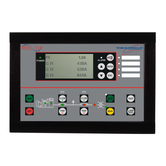
Page 5: Push-Buttons, Leds And Display
Dimensions Front dimensions H x W 160 x 220 mm (6.30” x 8.66”) Unit depth 54 mm (2.13 “) Push-Button Functions The push-buttons on the unit have the following functions: RUN: ▲: ▼: Normal Display: Scrolls Permits local Silences Local Horn and Normal display: Scrolls the the display up once. - Page 6 Permits local engine start and run. Mode Selection must be in MAN to enable this push-button. OFF: Stops the engine instantaneously. If the unit is in AUTO mode, the mode will change to MAN and the engine will immediately stop.
-
Page 7: Led Functions
Shutdown condition present, alarm condition may be present but shutdowns have higher precedent. Additional alarm Indication LEDs: Flashing: Active, non-acknowledged alarm(s) where output A or B is configured to LED 1, 2, 3 or 4. Steady: Active, acknowledged alarm(s) where output A or B is configured to LED 1, 2, 3 or 4. -
Page 8: Display Functions
MEC 310 OPERATION MANUAL Display Functions The display indicates both analog readings and alarms messages. Illustrated below are examples: MEC 310 Controller type, Hardware and Software Version. HW 1.02 SW 1.20.5 Fuel level 80 % Various analog values can be displayed, shown are: Fuel Level, Oil Pressure, Water Temp. -
Page 9: Disclaimer
The Product is delivered with certain factory setting. The factory settings are based on typical values and not to be considered acceptable for the piece of equipment it is intended to operate and protect. Thus precautions must be taken to confirm all settings to ensure these meet the requirements of the equipment being put into service. -
Page 10: Basic Operation
The controller provides a quick reference as to the alarm state level. The alarm LED on the controller can change between an amber or red state. If both alarms and a shutdown are present the LED will be red indicating the highest level of alarm, this being a shutdown condition. When there are only alarms present, the alarm LED will be amber. -
Page 11: Manual Operation Mode
In the Manual Operation Mode the remote start input is ignored, starting and stopping of the engine generator can only be achieved with the RUN and OFF push-buttons on the left side of the controller. Once a manual RUN is initiated the engine generator set will continue to operate until manually...
Need help?
Do you have a question about the MEC 310 - GENSET CONTROLLER and is the answer not in the manual?
Questions and answers