Table of Contents

Related Manuals for DUNIWAY Stockroom Terranova 924A


Summary of Contents for DUNIWAY Stockroom Terranova 924A
- Page 1 Terranova® 924A Single Thermocouple Gauge Control Unit Instruction Manual rev1016NC © 2016 Duniway Stockroom Corp. Telephone: 650-969-8811 Toll-Free (US/Canada): 800-446-8811 Fax: 650-965-0764 Email: info@duniway.com Web: www.duniway.com...
-
Page 2: Table Of Contents
Table of Contents Specifications Accessories Introduction Installation Mounting the Terranova® 924A Connecting the Pressure Gauge Operation Self Test Setup Mode Zero Adjustment Atmospheric Pressure Adjustment Changing Pressure Units Restoring Default Values Pressure Measurement Set Point Operation Serial Communication Analog Output Troubleshooting Changing Fuses Legacy Terranova®... -
Page 3: Specifications
Specifications Universal: 100V to 240V AC @ 50Hz to 60Hz; 40VA Operating Voltage 100V to 240V DC Pressure Display 3 Red LEDs - 3 digits (NNN) with pressure unit auto ranging Pressure Units Torr/mTorr [Default] ; mbar/µbar 1 x 10 Torr to 1000 Torr (Air/Nitrogen) Operating Range (1 x 10 mbar to 1000 mbar) 1 x 10 Torr to 1000 Torr (Air/Nitrogen) Measuring Range (1 x 10 mbar to 1000 mbar) -31 mTorr to 950 Torr... - Page 4 Explosive Gases Do not use the Terranova® 924A to measure the pressure of combustible gas mixtures. Although the pressure gauge normally operates at low temperatures, it is possible that momentary transients or controller malfunction can raise the pressure gauge above the ignition temperature of combustible mixtures. This, in turn, can create an explosion which can damage equipment and/or injure personnel.
-
Page 5: Introduction
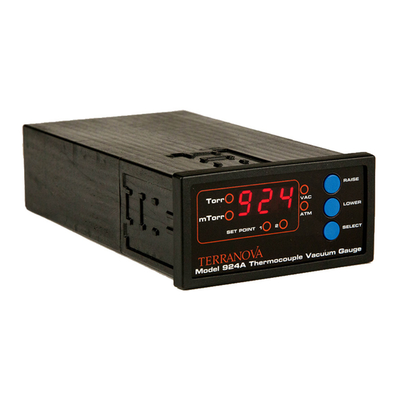
Introduction The Terranova® 924A Single Thermocouple Gauge Controller is designed to operate the industry-standard Type 531 or equivalent thermocouple gauges. The Terranova® 924A covers the pressure range between 1000 Torr to 1 x 10 Torr (1000 mbar to 1 x 10 mbar). Installation Mounting the Terranova® 924A The Terranova® 924A is housed in a standard 1/8 DIN box to allow for mounting on most equipment racks or cabinets. The dashed call-out dimensions in Figure 1 illustrate the proper cutout dimensions for the 1/8 DIN box. Figure 1 Terranova® 924A cutout and unit dimensions To properly mount the unit: 1. Locate the mounting clips included with the control unit 2. With the square end of the mounting clip facing towards the front panel, slide the beveled surfaces of the clip under the cutout located on each side of the control unit 3. Push the clip toward the back of the unit until the central tongue locks the clip 4. -
Page 6: Connecting The Pressure Gauge
Connecting the Pressure Gauge The Terranova® 924A has a female 9-pin D-sub connection located on the back of the control unit labeled SENSOR(S) to connect the pressure gauge cable (See Figure 2). User will require the Duniway gauge cable TC-924A-CBL-10 to connect the Varian Type 531 and equivalent gauges to the control unit. Figure 2 Terranova® 924A back panel The Terranova® 924A should be OFF before connecting the pressure gauge. Plugging or unplugging the pressure gauge while the control unit is ON can damage internal parts of the pressure gauge. To connect the Terranova® 924A to the respective pressure gauge: 1. -
Page 7: Operation
Operation Self Test The Terranova® 924A will perform a self test at power ON. The Self Test cycle is initiated by a BEEP sound followed by: 1. All LED and display indicators will become illuminated 2. Display reads the software version (e.g. 2.15) 3. Display reads the pressure units (e.g. TOR) The control unit will commence normal operation if Self Test is successful. Setup Mode Terranova® 924A unit parameters can be set or modified by the following five-step operation: 1. Press the SELECT button to zero-adjust the control unit. Use the RAISE or LOWER button to increase or decrease the VAC pressure value shown on the display. VAC LED will flash during adjustment. See Zero Adjustment. 2. Press the SELECT button a second time to adjust the atmospheric pressure value. Use the RAISE or LOWER button to increase or decrease the ATM pressure value shown on the display. ATM LED will flash during adjustment. See Atmospheric Pressure Adjustment. -
Page 8: Zero Adjustment
User must press and hold the RAISE or LOWER button until pressure value changes. Unit display will flash and pressure unit LED will illuminate during all four steps. Unit will return to normal operation in approximately 60 seconds if left unattended during Setup Mode; any changes will be saved. Timer is reset if any button is pressed during the 60-second timeout. Zero Adjustment Zero adjustment is recommended when installing a new pressure gauge or to restore pressure output accuracy. The Terranova® 924A can be either zero adjusted or set to a specific low pressure value via the VAC pressure value. Pressure reading must be less than approximately 50 mTorr (67 µbar) at initial set-up to adjust the VAC value. A long BEEP will be emitted if pressure reading is greater than 50 mTorr (67 µbar). Zero adjustment should be conducted before the atmospheric pressure adjustment. For zero adjustment, VAC value should be set to approximately 0.0 mTorr and system pressure must be lower than 1 x 10 Torr (1.3 x 10 mbar) to display accurate pressure measurements. If millibar units are to be used, VAC value adjustment should be conducted in Torr units. VAC value is appropriately converted when switching between pressure units. Although VAC pressure value is stored by the control unit, it will not be displayed in subsequent adjustments. Pressure reading range will shift if user accidentally changes VAC value during use. If this occurs, user should reset the Terranova® 924A and redo both the zero and atmospheric pressure adjustment. -
Page 9: Changing Pressure Units
Changing Pressure Units The Terranova® 924A is able to output pressure readings in Torr/mTorr or mbar/µbar. Default pressure units for the Terranova® 924A are Torr/mTorr. To change between pressure units: Disconnect AC power cord from control unit Simultaneously depress the SELECT, RAISE, and LOWER buttons Reconnect AC power cord to control unit Once power is restored, the unit will commence the Self Test. If pressure unit change is successful, two BEEPs will be emitted and the corresponding pressure units will appear on the display. Thereafter, the Terranova® 924A will resume normal operation. Restoring Default Values Restoring default parameters provides a starting point for control unit readjustment in the event pressure measurements become unreliable. -
Page 10: Pressure Measurement
Pressure Measurement Terranova® 924A operation is almost automatic and will commence after a successful Self Test. The Terranova® 924A is set to output pressure readings based on air/nitrogen. Although the type-531 thermocouple gauges have an upper reading range of 2 Torr, increasing the supplied current helps extend its pressure reading range. Pressure units will auto range during use as system pressure increases or decreases. The unit display will read OFF if the thermocouple tube or gauge cable is disconnected. Display will read HI only in millibar units if system pressure is greater than 950 mbar. Terranova® 924A pressure display resolution is as follows: Step Range 50 Torr greater than 300 Torr 20 Torr 60 Torr to 300 Torr 10 Torr 20 Torr to 60 Torr 5 Torr 10 Torr to 20 Torr 0.05 Torr... - Page 11 in which S is the set point pressure value in millitorr (or µbar). For example, if SET POINT 1 is 30 mTorr, its corresponding relay will activate once the pressure reading is below 30 mTorr and deactivate once the pressure reading is greater than 32.5 mTorr. If set point value is OFF, the respective relay will be disabled. Terranova® 924A set point pressure display resolution is as follows: Step Range 50 Torr greater than 300 Torr 20 Torr 60 Torr to 300 Torr 10 Torr 20 Torr to 60 Torr 5 Torr 10 Torr to 20 Torr 0.05 Torr 1 Torr to 10 Torr 5 mTorr 200 mTorr to 1000 mTorr 1 mTorr less than 200 mtorr Display resolution also applies to millibar units in the respective pressure ranges.
-
Page 12: Serial Communication
Serial Communication The INPUT/OUTPUT 15-pin D-sub port allows the user to remotely query the Terranova® 924A to read unit parameter values. The serial communication standard used for data transmission is RS-232. The RS-232 format for communication with the Terranova® 924A unit is as follows: RS-232 Settings 9600 baud No parity 8 bits 1 stop bit Full duplex Figure 4 illustrates the pin configuration for RS-232 communication. User will require the Duniway cable RS232-TN9DIN and a separate program, such as HyperTerminal, to send query characters and read output from the control unit. Table 2 lists the characters used by the Terranova® 924A to return unit parameters. RS-232 Standard 9-Pin Terranova®... -
Page 13: Analog Output
Character Query Output Format Notes Pressure reading ASCII Value 112 SET POINT 1 Value XeY R ASCII Value 49 SET POINT 2 Value XeY R ASCII Value 50 Pressure units Torr/mBar ASCII Value 117 Table 2 Serial Communication query characters Examples Pressure: 2.35 mbar p Output: 2.35e+0 Pressure: HI p Output: 999e+0 Pressure: OFF p Output: -9.9e-3 SET POINT 1 pressure: 57 mTorr (Relay ON) 1 Output: 57.0e-3 1... -
Page 14: Troubleshooting
Analog Output [V] Pressure 0.02 p ≥ 0 mTorr 0.50 10 mTorr 1.00 100 mTorr 1.50 1 Torr 2.00 10 Torr 2.50 100 Torr 3.00 OFF/HI Table 3 Analog output and calculated pressure values Pressure as a function of the analog output can be approximated by: P = 10 where V is the analog output in volts and P is pressure in mTorr (or μbar). For example, if V is equal to 2.00 V, P (rounded to the nearest one) is equal to 10 Torr. - Page 15 Pressure Gauge The type-531 thermocouple tube has internal resistance values indicative of an operational pressure gauge. User should first reset the Terranova® 924A to correct any controller problems. If resetting does not resolve the problem, user may clean the inside of the pressure gauge. A cleaning agent such as acetone or toluene may be used to carefully clear away any contaminants. The pressure gauge should be replaced if resistances greatly deviate or if cleaning does not provide reasonable pressure readings. Chemicals Many organic cleaning solvents, such as acetone, produce fumes that are toxic and/or flammable. Such solvents should only be used in well-ventilated areas and away from electronic equipment, open flames, or other potential ignition sources.
-
Page 16: Changing Fuses
Changing Fuses The Terranova® 924A contains two Type F, regular (or slow-blow) 1 A fuses. As shown in Figure 6, both fuses are held in the fuse assembly located on the back panel of the unit. Figure 6 Terranova® 924A power module To change fuses: 1. Unplug the line cord from the unit power module 2. Locate the fuse block immediately below the power cord socket 3. Press the tab of the fuse block and withdraw the assembly 4. Inspect and replace faulty fuse(s) 5. Reinsert fuse assembly into power module 6. Push fuse assembly into place until assembly tabs “click” The following is a list of suggested replacement fuses: Recommended Fuses Bussman GDB-1A... -
Page 17: Warranty
Warranty Duniway Stockroom Corporation (“DSC”) warrants all Terranova® products to be free of defects in material and workmanship for a period of one year from the date of shipment. At our option, we will repair or replace products which prove to be defective during the warranty period. Liability under this warranty is limited to repair or replacement of the defective item(s). Shipping damage is excluded from the scope of this warranty. Pressure gauges of all types are excluded from this warranty. Terranova® products are warranted not to fail to execute programming instructions due to defects in materials and workmanship. If DSC receives notice of such defects during the warranty period, DSC will repair or replace firmware that does not execute its programming instruction due to such defects. DSC does not warrant that the operation of the firmware or hardware will be uninterrupted or error-free. If this product is returned to DSC for warranty service, Buyer will prepay shipping charges and pay all duties and taxes for products returned to DSC. DSC will pay for the return of products to Buyer, except for products returned to a Buyer from a country other than the United States. Limitation of Warranty The foregoing warranty does not apply to the defects resulting from: 1. -
Page 18: Declaration Of Conformity
Declaration of Conformity Duniway Stockroom Corp. declares under its sole responsibility that the following products: Terranova® 924A Single Thermocouple Gauge Controller which displays the CE mark to which this declaration relates are in conformity with the following standards or normal documents: EMC Directive (89/336/EEC//93/68/EEC) Electromagnetic Compatibility Standards: EN 50081-1: 1992, EN 50082-1: 1993 EN 61326: 1997/A1: 1998/A2: 2002 Low Voltage Directive (73/23/EEC//93/68/EEC) Electrical / Technical Safety Standard: EN 61010-1: 1993/A2: 1995: 2001 following the provisions of the EMC directive (89/336/EEC) UL and CSA Listing Safety of Electrical Equipment for Laboratory Use Conforms to UL61010A-1, Issued 2002/01/30 Certified to CAN/CSA C22.2 No. 1010.1-92, 97 Telephone: 650-969-8811 Toll-Free (US/Canada): 800-446-8811 Fax: 650-965-0764 Email: info@duniway.com Web: www.duniway.com... -
Page 19: Appendix 1 Gauge Cable Diagram
Appendix 1 Gauge Cable Diagram Thermocouple Terranova® 924A Octal Connector Control Unit Pin 1 Pin 1 Pin 3 Pin 9 Pin 5 Pin 8 Pin 7 Pin 3 Drain Figure 1 Terranova® 924A to thermocouple gauge cable configuration Telephone: 650-969-8811 Toll-Free (US/Canada): 800-446-8811 Fax: 650-965-0764 Email: info@duniway.com Web: www.duniway.com... -
Page 20: Appendix 2 Notes On Terranova® Set Point Relays
Appendix 2 Notes on Terranova® Set Point Relays Figure 1 Heavy Duty Type AZ5 relay voltage-current relationship The Heavy Duty Type AZ5 relay is used in the Terranova® 924A to control external functions. As shown in Figure 1, maximum current varies from 2 A at 30 V DC (60 V AC) to 0.4 A at 150 V DC (300 V AC) for resistive loads. Protective Circuits for Inductive Loads A protective circuit or component is recommended when switching inductive loads to suppress sudden voltage spikes. One method to suppress high voltage spikes in an AC circuit is through the use of a “snubber” circuit. A “snubber” circuit consists of a capacitor and resistor across an inductive load. As shown in Figure 2, the “snubber” circuit is parallel to the high-current relay. - Page 21 Appendix 2 Notes on Terranova® Set Point Relays Figure 2 Example of a "snubber" circuit To calculate the appropriate capacitor C in microfarads [µF] and resistor R in ohms [Ω] to use in the “snubber” circuit, Paktron Capacitors’ Quencharc® technical note suggests the following empirical equations: /10 (1), and R=E/10I(1+50/E) (2), where I is the load current prior to contact opening in amperes [A] and E is the source voltage in volts [V]. For example, if Figure 2 shows a 1 A high-current relay with a 110 V AC source connected in series with the Terranova relay, I = 1 A and E = 110 V AC. Therefore, Equation 1 provides a capacitance value of 0.1 µF; Equation 2 provides a resistance value of approximately 8 Ω. Thus, a 0.1 µF capacitor and a 10 Ω resistor should be used for the “snubber” circuit. However, user must take into consideration the voltage and power rating of the capacitor and resistor, respectively, to meet the requirements of the circuit. Similar protective circuits or components should be considered to suppress current spikes in capacitive loads. Pancon Corporation. ‘2012 Catalog’. 2012. 18-19. Web. http://www.panconcorp.com/PDFs/Catalogs/Paktron_2012catalog.pdf Telephone: 650-969-8811 Toll-Free (US/Canada): 800-446-8811 Fax: 650-965-0764 Email: info@duniway.com Web: www.duniway.com...
Need help?
Do you have a question about the Terranova 924A and is the answer not in the manual?
Questions and answers