
Related Manuals for Yaesu FRG-7 Digital


Summary of Contents for Yaesu FRG-7 Digital
- Page 1 FRG-7 Digital Installation Manual Manual Version 1.2 Software version 1.4x Marcel Jacobs PA8MA...
-
Page 2: Introduction
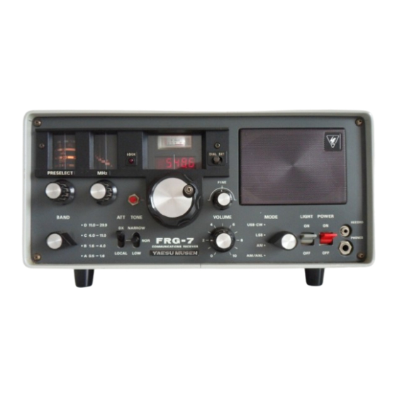
Introduction The Yaesu FRG-7 is a communications receiver, produced in the late 1970s and early 1980s. The range is from 500 kHz to 29.99 MHz. The FRG-7 is a triple conversion super heterodyne receiver. The tuning is based on the Wadley Loop principle, which was revolutionary at the time. -
Page 3: Table Of Contents
Contents Introduction ............................. 2 Built-in FRG-7 Digital ........................4 Package Contents FRG-7 Digital ....................4 Disassembling S-meter ......................5 Digital display assembly ......................5 Placement of TFT display ......................7 Arduino nano and board assembly ..................9 Wiring ............................11 Power supply ......................... -
Page 4: Built-In Frg-7 Digital
1 Built-in FRG-7 Digital 1.1 Package Contents FRG-7 Digital The package for creating the digital readout on the Yaesu FRG-7 consists of the following parts: • Double sided PCB with pre-programmed and calibrated Arduin Nano • 8-way flat cable with FC8 Pin Idc socket connectors on both sides •... -
Page 5: Disassembling S-Meter
1.2 Disassembling S-meter Unscrew the screws at the top, side and bottom (9 in total) and slide the chassis forward out of the housing. See picture 2 and 3. Picture 2 : Screws Picture 3: Chassis Now the S-meter must be removed. Unscrew the 2 small screws on the left and right of the meter. - Page 6 causes part of the display to sit above the opening in the front. This has been taken into account in the display. There is enough space left to clearly display both the frequency and the S-meter. The display consists of 3 parts: •...
-
Page 7: Placement Of Tft Display
Picture 8 : Flat cable with FPC adapter 1.4 Placement of TFT display The display can now be placed in the window of the S-meter. First a screw must be removed (see picture 9) for mounting the FPC adapter. Picture 9 : FPC mounting positie This M3 screw cannot be reused because it is too short. - Page 8 Picture 10 : Mounting display Picture 11 : Position display Because the display is higher than the opening of the S-meter, the bottom of the display must be placed on the black edge. This will cause the display to tilt backwards slightly. However, this does not disturb the reading.
-
Page 9: Arduino Nano And Board Assembly
Picture 13 : FPC print assembly If the 8-way flat cable was not yet connected, this can now be done. Pay attention to the marking on the PCB and the connector of the flat cable. See picture 8. Because the display does not cover the entire opening of the S-meter, some light from the scale illumination will remain visible in the window. - Page 10 Picture 15 : Mounting PCB The mechanical installation is now complete. You can then start making the necessary connections.
-
Page 11: Wiring
2 Wiring 2.1 Power supply The readout uses the power supply within the FRG-7. This power supply point can be found on the IF-AF unit with reference TP408 (on the edge near the cooling profile). This is approximately 10.6V. Picture 16 : Power supply FRG-7 TP408 Now make a connection between TP408 and the + of J1 on the PCB. -
Page 12: S-Meter
Connect the shielded cable to J4. Note the + and -. Picture 18 : VFO on J4 2.3 S-meter Because the display replaces the S-meter, the uC must ensure the correct reading. For this purpose, the signal from the S-meter is connected to the PCB at point J2 (signal) and J3 (ground). -
Page 13: Display
The COMMON connection must be connected to earth. There are plenty of options for this on the bottom of the IF-AF unit. The LSB tab is connected with a cable to J8 on the PCB of the FRG-7 Digital. The USB tab is connected to J9 on the PCB. - Page 14 connector of the flat cable. Picture 22 : Connector marking If everything is connected correctly, the total will look like this. Picture 23 : Total overview...
-
Page 15: Using Frg-7 Digital
3 Using FRG-7 Digital Once everything is connected, the radio can be turned on. Once again, make sure that you do not come into contact with the mains voltage. The display will start up with the logo and then show the frequency and S-meter. -
Page 16: Display Brightness
If you do want to remove it, the S-meter must be replaced with a 640 Ohm resistor. This can be done, for example, by connecting 560 and 82 Ohms in series. This resistor should be soldered over J2 and J3. 3.2 Display brightness The TFT display has a very high contrast and brightness. - Page 17 • Tune to a strong AM shortwave broadcast station. These are in a 5 kHz grid. Make sure the frequency readout ends with XX0.0 or XX5.0. • The MODE switch should be on AM. The station is audible but not in the middle of the filter •...
-
Page 18: Offset Ssb
• Once removed, the correct frequency for the AM station, tuned to the middle of the filter, will be shown on the display. 3.4 Offset SSB To use the offset setting for LSB and USB, this option must first be wired as described in chapter 2.4. -
Page 19: Offset Usb
• Close jumper J7. The following text appears on the display. Picture 29 : Start LSB offset • Close jumper J6 The display will now show the offset. Picture 30 : LSB offset at start • Now adjust the tuning to zero beat on the broadcast station. Picture 31 : LSB offset during setting •... - Page 20 • Tune to a strong AM shortwave broadcast station. These are in a 5 kHz grid. Make sure the frequency readout ends with XX0.0 or XX5.0. • Set the MODE switch to LSB. A tone will be heard. • Close jumper J7. The following text appears on the display. Picture 32 : Start USB offset •...
-
Page 21: Offset Removal Of Am, Lsb And Usb
After setting the offset, the mode is now also visible in the display. Picture 35 : AM mode Picture 36 : USB mode 3.5 Offset removal of AM, LSB and USB Sometimes it can be necessary to remove all the offset values, stored in EEPROM. The next procedure will make them all zero again. -
Page 22: Counter Calibration
If you have decided to perform the calibration again, the following procedure must be followed. • Make sure the FRG-7 with the FRG-7 Digital option is turned on for at least 30 minutes • Turn off the FRG-7 •... -
Page 23: Frg-7 Digital Schematic
5 FRG-7 Digital schematic Picture 39 : FRG-7 Digital schematic...
Need help?
Do you have a question about the FRG-7 Digital and is the answer not in the manual?
Questions and answers