Table of Contents
Advertisement
Quick Links
Advertisement
Table of Contents

Summary of Contents for Sofar PSC100 Series
- Page 1 All copy reserved ©Shenzhen SOFARSOLAR Co., Ltd. 1...
-
Page 2: Table Of Contents
Content 1 Basic Safety Information ....................1 1.1 Safety Markings .......................1 1.2 Symbol Interpretation ....................1 2 Safety instructions ......................2 2.1 Read before installation ..................2 2.2 Installation Tools ......................2 3 Product Introduction ....................... 4 3.1 Product Description ....................4 3.2 Product Model ...................... - Page 3 Please check our website at http://www.sofarsolar.com for lasted version. Scope of application The product manual describes the installation, electrical connection, commissioning, maintenance and troubleshooting of the Communication Box PSC100 series. The series includes the following models: PSC100, PSC100A, PSC100E. User manual version Version...
-
Page 4: Basic Safety Information
PSC100 series user manual 1.Basic Safety Information Please read the safety precautions in this manual carefully, as ignoring them may result in serious personal injury or death. If you have any questions while reading the following information, please contact Shenzhen SOFARSOLAR Co., Ltd. -
Page 5: Safety Instructions
Installation and maintenance should only be performed by a qualified electrical engineer for this operation. SOFAR Communication Box must be installed in full compliance with national and local grid standards and regulations. Read and understand all instructions contained in this manual and familiarize yourself ... - Page 6 PSC100 series user manual Crystal head crimping For compacting the crystal heads of pliers network cables Pneumatic drill For drilling holes Tighten or loosen hexagon socket head M5 hexagonal wrench cap screws Adjustable wrench For fixing expansion screws Laptop computer (with...
-
Page 7: Product Introduction
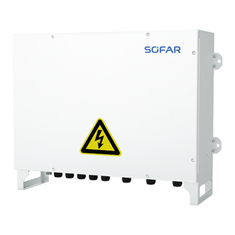
PSC100 series user manual 3.Product Introduction 3.1 Product Description SOFAR Communication Box PSC100* series integrates data collector, industrial ring switch, power line communication (PBUS) main module (CCO module), communication manager, single/three-phase lightning protector, etc. to collect data from PV subarray device. -
Page 8: Networking
PSC100 series user manual 4.Networking The optical fiber ring network (for PSC100/PSC100A) has both PBUS communication and RS485 communication. As shown in the figure below. PBUS communication: RS485 communication: All copy reserved ©Shenzhen SOFARSOLAR Co., Ltd. - Page 9 PSC100 series user manual The star network (for PSC100/PSC100A/PSC100E) has both PBUS communication and RS485 communication. As shown in the figure below. PBUS communication: RS485 communication: All copy reserved ©Shenzhen SOFARSOLAR Co., Ltd.
-
Page 10: Installation Method
Installation of SOFAR Communication Box should avoid sunshine, rain and snow accumulation. 5.2 Appearance Introduction and Packaging Information Please check the product to make sure it matches the specifications of the SOFAR Communication Box you purchased after opening the package. All copy reserved ©Shenzhen SOFARSOLAR Co., Ltd. - Page 11 PSC100 series user manual 5.2.1 Appearance Introduction Name Description AC INPUT 220Vac AC power supply L/N port PBUS communications module 01, Three-phase AC line AC INPUT/PBUS 01 L1/L2/L3 AC INPUT/PBUS 02 PBUS communication module 02, three-phase AC line L1/L2/L3 DI DO AI DI DO AI port RS485-1/2、RS485-3/4...
-
Page 12: Device Installation
PSC100 series user manual Quick Installation Guide Shipment Inspection Report Certificate of Conformity Guarantee Card Desiccant 5.3 Device Installation 5.3.1 Selection of Mounting Location 1. The following factors must be taken into account in the selection of the mounting location: Mounting method and location shall be appropriate for the weight and size of the ... - Page 13 PSC100 series user manual 2. mounting space: In order to ensure good heat dissipation and easy disassembly, the minimum clearance around the Communication Box shall not be less than the following values, as shown in the following figure. Upper: 500mm; lower: 500mm; front: 800mm; both sides: 200mm.
- Page 14 PSC100 series user manual C. Install the case and hang the machine on the wall, paying special attention to supporting the machine and tightening the expansion screws; as shown in the figure below. 2.Vertical bracket mounting A. Fix the mounting bracket on the ground, and connect the bracket to the ground firmly and reliably;...
- Page 15 PSC100 series user manual 3.Horizontal placement A. The Communication Box can be placed horizontally to work as shown in the left figure below. B. The Communication Box needs to be placed in a place where it can be fixed inside the house and fixed firmly and reliably.
-
Page 16: Cable Connection And Networking
PSC100 series user manual 6.Cable Connection and Networking 6.1 System Communication Method The Communication Box has a variety of combinations of communication methods, two kinds of RS485 and PBUS communication modules for down, and 2 kinds of fiber-optic ring network, Ethernet for up, as shown in the table below:... - Page 17 PSC100 series user manual 6.1.2 Downward Communication Method 1. PBUS (For PSC100/PSC100A/PSC100E) The communication mode of PBUS communication module is shown in the figure below.The communication line of PBUS communication module is connected to the converging main switch SW near the side of the box transformer.In addition,the miniature...
-
Page 18: Description Of Internal Structure And Wiring
PSC100 series user manual 6.2 Description of Internal Structure and Wiring 6.2.1 Internal Structure The internal structure of the Communication Box is described in the following figure. Note: ★ indicates that the model has the module, the number of ★ represents the number of the module. - Page 19 PSC100 series user manual Name PSC100 PSC100A PSC100E Industrial ring switches ★ ★ Fusion reel ★ ★ RS485 terminal blocks ★ ★ ★ Data Repeater ★★ ★★ ★★ Fuse holder 01 ★ ★ ★ 3P AC surge protector ★ ★...
- Page 20 PSC100 series user manual When connecting dual PBUS communication module, the external RS485 interface can be connected to RS485-3/4. When the PBUS communication module is not connected, the external RS485 interface can be connected to RS485-1/2/3/4. RS485 Cable specifications and installation requirements: RS485 communication cable is recommended to use shielded twisted-pair cable with a conductor cross-sectional area of 1mm².
- Page 21 PSC100 series user manual MV Transformer Station Wire greater than 12awg (core 3mm2) is recommended for R, S, and T three-phase power lines. 4.Ethernet port(For PSC100/PSC100A/PSC100E) Connect the LAN3 port of the Communication Manager to the external switch. 5.Fibre-optic port(For PSC100/PSC100A)...
- Page 22 PSC100 series user manual 6.Single-phase power input port(L/N/PE) Input line voltage range: 100-240VAC; Single-phase AC input frequency: 50-60Hz; AC input wire specifications and crimping requirements are as follows: Grade Description Value Outer diameter of wire Less than or equal to 18mm Cross-sectional area of copper conductor Recommended 2.5~4mm2...
-
Page 23: Parameter Configuration
PSC100 series user manual 7.Parameter Configuration Open the Communication Box housing before parameter configuration. The recommended browsers are google chrome or microsoft edge chrome. 7.1 Login Connect one end of the network cable to the computer's network port and the other end to the LAN4 port of the Communication Manager. -
Page 24: Device Maintenance
PSC100 series user manual 7.4 Device Maintenance 1、Add inverter If the Communication Box model is PSC100A/PSC100E, the user is required to select the PBUS management channel to be configured. As shown in the figure below. Automatic search for inverters ... - Page 25 PSC100 series user manual Tick the inverters you have found and click "ADD". Then, click "Stop Searching". Manually add inverter As shown in the figure below, enter the inverter SN and its address that you want to add and click Add.
- Page 26 PSC100 series user manual 2、Modifying the inverter address After adding an inverter, you can modify the address of the inverter. Click the "Edit" button as shown below. Then, enter the actual inverter address and click "Confirm". As shown in the figure below.
- Page 27 PSC100 series user manual The inverter communication address must not be set to 248. 3、Delete inverter Select the device you want to delete in the device list and click the "DEL" button. As shown in the figure below. All copy reserved ©Shenzhen SOFARSOLAR Co., Ltd.
- Page 28 PSC100 series user manual If you want to remove all inverters, click "Clear Whitelist". All copy reserved ©Shenzhen SOFARSOLAR Co., Ltd.
-
Page 29: Device Monitor
PSC100 series user manual 7.5 Device Monitor 1、View Inverter Version On the device monitoring page, select the PBUS management channel and type of the device you want to upgrade. Then click "ver" to view the version number of the device. -
Page 30: Upgrade
PSC100 series user manual 7.6 Upgrade 1、Documentation upgrades Click "Upload file" to import the database file. When the upload progress reaches 100%, click on "Start the Application". 2、CCO upgrade Click "Upload" to import the latest firmware. Tick the upgraded CCO and click "Start Upgrade". -
Page 31: System Settings
PSC100 series user manual Click "Upload" to import the latest firmware. When the upload progress reaches 100%, click "Start Upgrade" again. 7.7 System Settings On the system settings page, users can view the current software version, CCO settings, change password, and time settings. - Page 32 PSC100 series user manual 2、Change Password Enter the latest password twice and click "Save Settings". 3、Time Setting Manual Setting: select the time zone, turn off the automatic synchronisation button, click "Get local time" to get the current time. Click "set Time" to modify the time of the Communication Box.
- Page 33 PSC100 series user manual Auto Synchronisation: Just select the time zone and turn on the Auto Sync button. All copy reserved ©Shenzhen SOFARSOLAR Co., Ltd.
-
Page 34: Troubleshooting & Maintenance
PSC100 series user manual 8.Troubleshooting & Maintenance For maintenance of the Communication Box, it is necessary to cut off all power supply to the Communication Box, including the communication power supply of the PBUS communication module and the auxiliary power supply. - Page 35 PSC100 series user manual replace the PBUS Communication Module CCO Module board Check the inverter display for a blinking Inverter internal PBUS "PBUS communication module" communication STA communication mark. If not, replace the module failure inverter monitor board Other loads on the communication loop of...
-
Page 36: Technical Parameter
PSC100 series user manual 9.Technical Parameter Model PSC100 PSC100A PSC100E Auxiliary power Voltage range: 100-240VAC, frequency range: 50-60Hz supply input Communication ETH/RS485/PBUS/SFP ETH/RS485/PBUS/SFP ETH/RS485/PBUS method RS485 PBUS Fibre-optic port Operating temperature -30℃~+60℃ Storage and transport -40℃~+85℃ temperature Altitude ≤4000m Relative humidity ≤95%, non-condensing... - Page 37 PSC100 series user manual All copy reserved ©Shenzhen SOFARSOLAR Co., Ltd.
Need help?
Do you have a question about the PSC100 Series and is the answer not in the manual?
Questions and answers