Table of Contents
Advertisement
Quick Links
Advertisement
Table of Contents

Related Manuals for Spectra LR60


Summary of Contents for Spectra LR60
- Page 1 LR60 Laser Receiver User Guide •...
- Page 2 Introduction ® Thank you for choosing the Spectra Precision Laser Receiver LR60. The laser receiver is a rugged, multi-purpose, electronic sensor that detects laser light generated by rotating laser transmitters. The receiver works with nearly all models of rotating lasers and detects both visible and invisible beams.
-
Page 3: Maintenance And Care
Safety Please follow all operating and safety instructions in this guide and that of your machinery. Perform periodic checks of the product’s performance. Trimble or its representatives assume no responsibility for results of the use of this product including any direct, indirect, consequential damage, and loss of profits. Check your work frequently. -
Page 4: Features And Functions
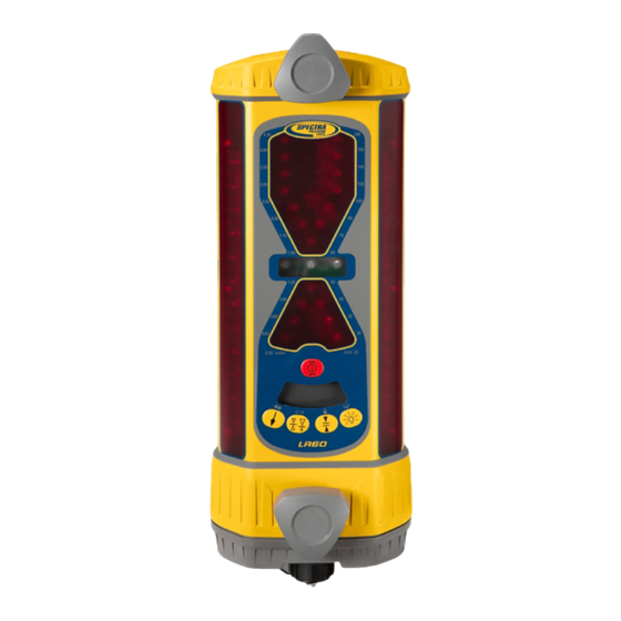
Features and Functions 1. Aluminum-Cast Upper and Lower Housings—protect the receiver. 2. Polycarbonate Housing—protects the electronics. 3. Receiving Windows—include four sets of photocell that are equally spaced to allow for 360 degree reception. 4. Ultra-Bright LEDs—are highly visible and graphically display blade or bucket position. The green on-grade LEDs and red off-grade LEDs provide quick visual indication. -
Page 5: Controls And Displays
Controls and Displays Touch Panel Power Button Touch-Panel Lock Beam Averaging Indication Communication Line Laser (Not Used) Out-of-Level Indication Display Brightness Plumb Button Button Deadband Center/Offset (Accuracy) On-Grade Button Button Deadband Touch-Panel Lock (Accuracy) Beam Averaging Indication Indication Out of Level, Communication RPM Indication Radio Link... -
Page 6: Installing And Recharging The Batteries
Installing and Recharging the Batteries Alkaline Batteries 1. Hold the receiver so the accessory connector is pointing up. 2. Remove the dust cap from the accessory connector. 3. Loosen the two thumb screws and remove the battery access cover. 4. Install four “C” cell alkaline batteries as shown on the label diagram inside the battery compartment noting the (+) and (–) terminals. -
Page 7: Battery Safety
Battery Safety Built-in overcharging protection prevents damage to the receiver if it is left on charge after being fully charged. Charge protection also prevents damage if you accidentally try to recharge alkaline batteries. CAUTION: Do not attempt to charge alkaline or other disposable batteries. Note: The batteries should only be charged when the receiver is between 0 °C to 45 °C (32 °F to 113 °F). -
Page 8: Using The Receiver
Using the Receiver Operation Power Button Press the power button. All the LEDs light and then each row lights from top to bottom. The LCD cycles through its symbols. If the receiver is out of the laser beam, the center green LED flashes and the LCD lights to confirm power is on. If the receiver is in a laser beam, a corresponding LED grade display lights. - Page 9 Center/Offset On-Grade Button Center on-grade or “grading mode” is selected when grade information is useful both above and below on-grade, as with typical grading operations. Offset on-grade or “excavator mode” is selected when using a backhoe or excavator. The excavator mode gives more information and a larger display above on-grade.
- Page 10 Display-Brightness Button The display-brightness button controls the LED brightness. Options include Bright and Dim. Use Dim for normal and lower light conditions and Bright for sunny daytime operation. Dim conserves battery life by approximately 50%. Press the display-brightness Display Bright button to cycle through both options.
-
Page 11: Installation
Out-of-Beam Indication The LED display indicates if the receiver has moved beyond the vertical laser-reception range. A sequence of LEDs indicates which direction the implement must be moved to pick up the beam. The out-of-beam indication continues for approximately two minutes. - Page 12 Angle Compensation for Excavation (ACE) Mode The horizontal grade checking width is wider as the receiver setup length is decreased. For example, the closer the receiver is mounted to the bucket, the wider the grade checking range will be. The most accurate and repeatable method for checking grade is with the bucket cylinder fully retracted.
- Page 13 Grading Center Laser On-grade Finished Elevation Benchmark 1. Position the machine so the blade can be set to the desired finished elevation (typically on a benchmark or hub stake). 2. Set up the laser in an appropriate location for receiver visibility and efficient machine operation.
- Page 14 7. Select the desired deadband and brightness. Note: The LED grade display indicates which way to move the blade using the machine’s controls to maintain an on-grade reading. 8. Make a sample pass with the blade “on-grade” and check to make sure the elevation is correct.
- Page 15 4. If the setup number is passed, simply continue pressing the button until it cycles to the correct number again. The number may also be selected by pressing and releasing the button while in the setup length entry mode. The LEDs change one increment each time the button is pressed.
- Page 16 4. Slide the receiver up or down until you get an on-grade display. 5. Select the desired deadband and begin excavating. 6. Take grade readings with the bucket retracted and the LEDs solid. ACE mode 1. Mount the mast on the side of the dipper arm so that it points to the bucket teeth. 2.
- Page 17 In-Trench Setup – Bucket Leveled Mast pointed to bucket pivot pin Laser Setup length – Center ongrade to bucket pivot pin Excavation Depth 1. Position the machine, and dig to the desired finished elevation. 2. Level the bucket and place the bottom of the bucket at the finished elevation. 3.
- Page 18 5. Enter the ACE mode. 6. Press and hold the plumb button to scroll up the setup-length scale and release the button when the lit LED is closest to the measured setup length. The LED flashes to confirm the setting. 7.
- Page 19 2. Position the receiver so that the setup length (L) is the distance from the bucket teeth to the offset on-grade symbol on the back of the receiver. (Set up to the center on-grade symbol if center on-grade will be used). 3.
- Page 20 1. Level the bucket and position the machine so a measurement can safely be obtained on the dipper arm. 2. Set up the laser and turn it on. 3. Determine the distance from the laser to the bottom of the trench (L). The length is the height of the instrument (HI) plus the depth of cut from the benchmark to the bottom of the trench (C).
- Page 21 Secondary Functions While the receiver is on, press and hold the power button and then press the touch- panel buttons to activate secondary or “shift” functions that are indicated by the symbols above the button. Laser Out of Level This function is for use with lasers that have the ability to indicate that they are out of level by changing the RPM of the laser.
- Page 22 Touch-Panel Lock Press and hold the power button and then press the accuracy button to turn the touch- panel lock function on and off. When the function is on, the lock symbol appears on the LCD. Buttons cannot be changed and accidental changes from dirt or debris knocking the buttons are prevented.
-
Page 23: Specifications
Specifications Beam Reception Range 360 degrees Operating Range Over 460 m (1500 ft) radius, depending on laser Laser RPM Minimum: 105; Maximum: 1200 Vertical Reception 222 mm (8.75 in.) Accuracy: On-Grade Deadbands Grading Excavating Setup 5 mm (0.20 in.) 6 mm (0.25 in.) Fine 10 mm (0.40 in.) 12 mm (0.50 in.) -
Page 24: Warranty
Warranty Trimble warrants the receiver to be free of defects in material and workmanship for a period of two years. Trimble or its authorized service center will repair or replace, at its option, any defective part for which notice has been given during the warranty period. If required, travel and per diem expenses to and from the place where repairs are made will be charged to the customer at the prevailing rates.
Need help?
Do you have a question about the LR60 and is the answer not in the manual?
Questions and answers