Siemens SIMATIC IOT Operating Instructions Manual
Hide thumbs
Also See for SIMATIC IOT:
- Quick install manual (2 pages) ,
- Operating instructions manual (64 pages) ,
- Quick install manual (2 pages)
Table of Contents
Advertisement
SIMATIC IOT2050
SIMATIC IOT
SIMATIC IOT2050
Operating Instructions
03/2024
A5E39456816-AF
Preface
Overview
Safety instructions
Installing and connecting
the device
Software and
commissioning
Expand device
Maintaining and repairing
the device
Certificates and approvals
Dimension drawings
Technical specifications
Hardware descriptions
Technical support
Markings and symbols
List of abbreviations
1
2
3
4
5
6
7
8
9
10
A
B
C
Advertisement
Table of Contents

Related Manuals for Siemens SIMATIC IOT


Summary of Contents for Siemens SIMATIC IOT
- Page 1 SIMATIC IOT2050 Preface Overview Safety instructions Installing and connecting the device SIMATIC IOT SIMATIC IOT2050 Software and commissioning Expand device Operating Instructions Maintaining and repairing the device Certificates and approvals Dimension drawings Technical specifications Hardware descriptions Technical support Markings and symbols...
- Page 2 Note the following: WARNING Siemens products may only be used for the applications described in the catalog and in the relevant technical documentation. If products and components from other manufacturers are used, these must be recommended or approved by Siemens. Proper transport, storage, installation, assembly, commissioning, operation and maintenance are required to ensure that the products operate safely and without any problems.
-
Page 3: Preface
The following generic terms are used in this documentation: Generic term Specific name Device IOT2050 device Arduino shield ARDUINO UNO (Rev3) The manual is delivered online, you can download the document from Central technical support (https://support.industry.siemens.com/cs/ww/en/). SIMATIC IOT2050 Operating Instructions, 03/2024, A5E39456816-AF... - Page 4 Preface Figures This manual contains figures of the described devices. The supplied device might differ in some details from the figures. Within some of the figures, one device is used to represent all devices. History The following editions of these operating instructions have been published: Edition Comment 03/2020...
-
Page 5: Table Of Contents
Table of contents Preface ..............................3 Overview ..............................9 Product description ......................9 Configuration plan ......................10 Structure of the devices ..................... 11 1.3.1 IOT2050 SM ........................11 1.3.2 Other configurations for IOT2050 ..................12 1.3.3 Status displays ........................13 Accessories ........................ - Page 6 Table of contents 4.2.1 Overview ........................... 36 4.2.2 Install sample image to eMMC with single USB stick ............37 4.2.3 Setting up the IOT2050 with example image ..............39 4.2.3.1 Installing the SD-card Example image ................. 39 4.2.3.2 Remote access with Putty SSH Connection ................. 39 4.2.3.3 Remote access with UART connection ................
- Page 7 Table of contents Dimension drawings ..........................93 Dimension drawings ......................93 Dimension drawings SM..................... 94 Dimension drawings mounting ..................94 Technical specifications ........................96 IOT2050 SM ........................96 9.1.1 General technical specifications ..................96 9.1.2 Electromagnetic compatibility .................... 97 9.1.3 Ambient conditions......................
- Page 8 Table of contents Interfaces ........................127 List of abbreviations .......................... 128 Glossary ............................. 130 Index ..............................132 SIMATIC IOT2050 Operating Instructions, 03/2024, A5E39456816-AF...
-
Page 9: Overview
Overview Product description The devices of the SIMATIC IOT family offer a robust, compact and flexible solution with a focus on the IOT environment and round off the SIMATIC IPC product range in the lower output range. Features • High degree of ruggedness •... -
Page 10: Configuration Plan
Overview 1.2 Configuration plan Configuration plan Depending on the industrial area of application, the following SIMATIC IOT devices are available with the following features: IOT2050 Basic IOT2050 Advance IOT2050 M.2 IOT2050 SM 6ES7647-0BA00-0YA2 6ES7647-0BA00-1YA2 6ES7647-0BB00-1YA2 6ES7647-0CA00-1AA2 Processor TI SOC AM6528 GP... -
Page 11: Structure Of The Devices
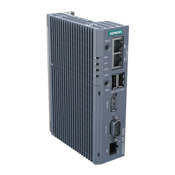
Overview 1.3 Structure of the devices Structure of the devices 1.3.1 IOT2050 SM The following figures show the configuration and interfaces of the SIMATIC IOT2050 SM. ① Ethernet interfaces 100/1000 Mbps ⑦ LED display, see section "Status displays (Page 13)" ②... -
Page 12: Other Configurations For Iot2050
Overview 1.3 Structure of the devices 1.3.2 Other configurations for IOT2050 The following figures show the configuration and interfaces of the SIMATIC IOT2050. ① Ethernet interfaces 100/1000 Mbps ⑦ LED display, see section "Status displays (Page 13)" ② For IOT2050 Basic (FS02), IOT2050 Advance ⑧... -
Page 13: Status Displays
This chapter contains the scope of accessories valid at the time these operating instructions were written. The following accessories are not included in the scope of delivery and can be ordered separately. Additional accessories can be found on the Internet at: Industry mall ((https://mall.industry.siemens.com/)) Name Specification... -
Page 14: Safety Instructions
Safety instructions General safety instructions WARNING Life-threatening voltages are present with an open control cabinet When you install the device in a control cabinet, some areas or components in the open control cabinet might be carrying life-threatening voltages. If you touch these areas or components, you might be killed by electric shock. Switch off the power supply to the cabinet before opening it. - Page 15 Safety instructions 2.1 General safety instructions NOTICE Use in the scope of application for the UL61010-2-201 When the device is used in the area of Industrial Control Equipment in accordance with UL61010-2-201, note that the device is classified as "Open equipment". Open equipment must be installed within an enclosure which protects you from hazards, including mechanical hazards, electrical shock and spread of fire.
- Page 16 Safety instructions 2.1 General safety instructions Battery and rechargeable battery WARNING Risk of explosion and release of harmful substances Improper handling of lithium batteries can result in an explosion of the batteries. Explosion of the batteries and the released pollutants can cause severe physical injury. Worn batteries jeopardize the function of the device.
-
Page 17: Cybersecurity Information
Siemens' products and solutions undergo continuous development to make them more secure. Siemens strongly recommends that product updates are applied as soon as they are available and that the latest product versions are used. Use of product versions that are no longer supported, and failure to apply the latest updates may increase customers' exposure to cyber threats. - Page 18 Thus, please consult your security expert for final assessment and configuration. Further, as already mentioned in IndustrialSecurity (https://www.siemens.com/industrialsecurity). Please note (i) that you are responsible for preventing unauthorized access to your plants, systems, machines, and networks, and (ii) that you should only connect such systems, machines, and components to an enterprise network or the internet if and to the extent such a connection is necessary and only when appropriate security measures (e.g.
-
Page 19: Installing And Connecting The Device
Installing and connecting the device Preparing for installation 3.1.1 Checking the delivery Procedure 1. When accepting a delivery, please check the packaging for visible transport damage. If any transport damage is present at the time of delivery, lodge a complaint at the shipping company in charge. - Page 20 Installing and connecting the device 3.1 Preparing for installation 5. If the contents of the packaging are incomplete, damaged or do not match your order, inform the responsible delivery service immediately. WARNING Electric shock and fire hazard due to damaged device A damaged device can be under hazardous voltage and trigger a fire in the machine or plant.
-
Page 21: Identification Data Of The Device
Installing and connecting the device 3.1 Preparing for installation 3.1.2 Identification data of the device The device can be clearly identified with the help of this identification data in case of repairs or theft. You can find this information on the rating plate. The following illustration shows an example. -
Page 22: Permitted Mounting Positions And Mounting Types
Installing and connecting the device 3.1 Preparing for installation 3.1.4 Permitted mounting positions and mounting types The device can be mounted horizontally or vertically on a DIN rail or to a wall. Vertical mounting position, preferred Horizontal mounting position Consider the permitted temperature range for operation that depends on the mounting position in accordance with the "Technical specifications (Page 96)"... -
Page 23: Mounting The Device
• Install all the expansions in the device before mounting the device on a DIN rail or a wall, see section "Expand device (Page 51)". • Siemens recommends you use 0.6 Nm tightening torque to install the mounting clamps and brackets. -
Page 24: Mounting On Din Rails
Installing and connecting the device 3.2 Mounting the device 3.2.2 Mounting on DIN rails 3.2.2.1 Secure the mounting clips Requirement • The DIN rail is installed at the installation site (35 mm standard profile). • Mounting bracket and mounting clamps •... -
Page 25: Mounting On Din Rails
Installing and connecting the device 3.2 Mounting the device IOT2050 SM Other configurations for IOT2050 3.2.2.2 Mounting on DIN rails Mounting 1. Place the device and rail clamp on the upper edge of the standard profile rail at the position shown and push the device down. - Page 26 Installing and connecting the device 3.2 Mounting the device Vertical Horizontal Removing 1. Push down the device until it is released by the rail clamp. 2. Swing the device out of the standard profile rail. 3. Lift the device up and off. SIMATIC IOT2050 Operating Instructions, 03/2024, A5E39456816-AF...
-
Page 27: Wall Mounting
Installing and connecting the device 3.2 Mounting the device 3.2.3 Wall mounting 3.2.3.1 Vertical wall mounting The device is suitable for horizontal or vertical wall mounting. Note The device must be installed on the plate of an enclosure. Requirement • Two mounting brackets •... -
Page 28: Horizontal Wall Mounting
Installing and connecting the device 3.2 Mounting the device 3.2.3.2 Horizontal wall mounting The device is suitable for horizontal or vertical wall mounting. Requirement • Two mounting brackets • Two screws • T8 screwdriver Procedure for mounting 1. Lay the mounting brackets on the rear of the device. 2. -
Page 29: Connecting The Device
Installing and connecting the device 3.3 Connecting the device Connecting the device 3.3.1 Notes on connecting WARNING Risk of lightning strikes A lightning flash may enter the mains cables and data transmission cables and jump to a person. Death, serious injury and burns can be caused by lightning. Take the following precautions: •... -
Page 30: Connecting The Function Earth
Installing and connecting the device 3.3 Connecting the device NOTICE Damage through regenerative feedback Regenerative feedback of voltage to ground by a connected or installed component can damage the device. Connected or built-in I/Os, for example, a USB drive, are not permitted to supply any voltage to the device. -
Page 31: Connecting The Power Supply
Installing and connecting the device 3.3 Connecting the device Requirement • T20 screwdriver • Cable lug for M4 • Function earth with minimum cross-section of 2.5 mm copper cable Procedure Clamp the cable lug on the function earth. Firmly attach the cable lug to the function earth connection on the device using the M4 thread with the torque of 1 Nm (see part labeled). - Page 32 Installing and connecting the device 3.3 Connecting the device Requirement • You are using the supplied terminal. • A two-core cable meet the following requirements: – a copper (Cu) cable with cross-section of 0.75 mm to 2.5 mm – rated temperature 70 °C •...
-
Page 33: Iot2050 Sm
Installing and connecting the device 3.3 Connecting the device 3.3.4 IOT2050 SM 3.3.4.1 Installing and removing the expansion cable Note Use the IO expansion cable in accessory kit When connecting the S7-1200 modules, only use the IO expansion cable in accessory kit. If you use a wrong cable and damage your device, the warranty becomes void. -
Page 34: Connecting The Ethernet
Installing and connecting the device 3.3 Connecting the device Table 3- 2 Removing the female connector of the expansion cable Task Procedure 1. Ensure that the CPU and all S7-1200 equipment are disconnected from electrical power. 2. Unlock the connector: –... -
Page 35: Software And Commissioning
Software and commissioning Software and commissioning Operating system and software for the SIMATIC IOT devices are freely programmable and are loaded from the Micro SD/eMMC card when the device is booted. For SIMATIC IOT2050 6ES7647-0BA00-1YA2: The device is capable of "Secure Boot", which means it only boots from trusted contents if enabled. -
Page 36: Install Example Image On Emmc
Software and commissioning 4.2 Install example image on eMMC Install example image on eMMC 4.2.1 Overview This chapter describes how to install the example image on the eMMC of the IOT2050. Note As IOT2050 doesn't have eMMC, this procedure is not applicable for IOT2050 Basic (6ES7647- 0BA00-0YA2). -
Page 37: Simatic Iot2050
SIMATIC IOT2050 Image must install an SD-Card sample image with Debian- SD-Card example based Linux operating system. image (https://support.ind ustry.siemens.com/ cs/ww/en/view/109 741799) SSH Client For remotely access to the SIMATIC IOT2050. Putty In this document "PuTTY" is used. Note: Besides PuTTY, you can also use the built-in SSH client in Windows 10 or Linux. - Page 38 Software and commissioning 4.2 Install example image on eMMC 7. Power off the IOT2050. 8. Safely remove the USB flash drive or SD card. 9. Power on the IOT2050. IOT2050 now booted in eMMC Use two different USB flash drives 1.
-
Page 39: Setting Up The Iot2050 With Example Image
Software and commissioning 4.2 Install example image on eMMC 4.2.3 Setting up the IOT2050 with example image 4.2.3.1 Installing the SD-card Example image To transfer the SD card image to a micro SD card, perform the following steps: 1. Insert the SD-card via SD-card adapter in the SD-card slot (Page 51) of your engineering station. - Page 40 Software and commissioning 4.2 Install example image on eMMC Access IOT2050 with Putty 1. Connect the engineering station and the SIMATIC IOT2050 with an Ethernet cable. Note: The SIMATIC IOT2050 has a static IP address by default, which is 192.168.200.1. For version 1.0.2 this IP address is set to X1P2, but from version 1.1.1 it is set to X1P1.
-
Page 41: Remote Access With Uart Connection
Software and commissioning 4.2 Install example image on eMMC 6. When connecting via SSH for the first time, a warning dialog appears indicating that it is necessary to update the SSH key. Press the "Yes" button to continue. 7. Enter "root" after "login as" and then enter the password for "root". You will be prompted to change the root password the first time you log in. - Page 42 Software and commissioning 4.2 Install example image on eMMC Access IOT2050 with UART 1. Loosen the shield cover and remove it. 2. Connect the USB end of UART cable to the engineering station. 3. In engineering station, type "Device Manager" in the search box on the taskbar, then select from the menu.
- Page 43 Software and commissioning 4.2 Install example image on eMMC 6. Configure the Putty connection. – Connection type: Serial – Serial production line: COM6 (We use COM6 for demonstration, which is the port number obtained from step 3.) – Speed: 115200 7.
-
Page 44: Setting Up Network Interface
Software and commissioning 4.2 Install example image on eMMC 8. Enter "root" after "login as" and then enter the password for "root". You will be prompted to change the root password the first time you log in. Change the password when prompted. 9. - Page 45 Software and commissioning 4.2 Install example image on eMMC 5. To access the "Edit a connection" page, click "Edit a Connection" and select the ethernet interface. Then, click the "Edit...". 6. Now you can configure the connection on the "Edit a connection" page. SIMATIC IOT2050 Operating Instructions, 03/2024, A5E39456816-AF...
-
Page 46: Installing Software On Iot2050
Software and commissioning 4.2 Install example image on eMMC Use USB Wifi dongle to connect the IOT2050 to a wireless access point 1. Insert your USB Wifi dongle into the IOT2050 device. 2. Navigate to "Activate a connection" and select the wireless access point that you want to connect to. - Page 47 Software and commissioning 4.2 Install example image on eMMC Install software 1. Open a serial Putty connection and log in as root. 2. Update repositories by typing apt update. 3. Type apt install <name of software> 4. Accept all licenses during installation. Remove software 1.
-
Page 48: Change Boot Order Of Iot2050
4.2.3.6 Change boot order of IOT2050 IOT2050 Advance and IOT2050 M.2 have internal eMMC which is automatically set as the first boot device for FS:01, FS:02 and FS:04. Here (https://support.industry.siemens.com/forum/ww/en/posts/overview-about-fs-states-of- iot2050/273280/?page=0&pageSize=10) you can find more information on functional state(FS). Note mmc1 refers to eMMC, mmc0 refers to the SD card, and usbx refers to the USB slots. -
Page 49: Using Uart Connection
Software and commissioning 4.2 Install example image on eMMC 4.2.3.7 Using UART connection You can use the UART connection to perform the following tasks: • Enter u-boot shell • Change the boot order • Select a specific boot device Permanently change boot order 1. - Page 50 Software and commissioning 4.2 Install example image on eMMC 2. To change the boot order, type setenv boot_targets "[devices]" 3. To continue boot with the changed boot order, type boot Select boot device only for the next boot 1. Interrupt the boot process by hitting any key when prompted to "Hit the Spacebar to stop autoboot".
-
Page 51: Expand Device
Expand device Insert Micro SD card/Nano SIM card Applicable Configuration This operation is only applicable for the following configurations: • IOT2050 Basic: 6ES7647-0BA00-0YA2 • IOT2050 Advance: 6ES7647-0BA00-1YA2 • IOT2050 M.2: 6ES7647-0BB00-1YA2 • IOT2050 SM: 6ES7647-0CA00-1AA2 Requirement • The device is disconnected from the power supply. •... -
Page 52: Install Arduino Shield
Expand device 5.2 Install Arduino shield Install Arduino shield Applicable Configuration This operation is only applicable for the following configurations: • IOT2050 Basic: 6ES7647-0BA00-0YA2 • IOT2050 Advance: 6ES7647-0BA00-1YA2 • IOT2050 M.2: 6ES7647-0BB00-1YA2 Requirement • The device is disconnected from the power supply. •... - Page 53 Expand device 5.2 Install Arduino shield 1. Loosen the shield cover. Carefully press with the blade of a flat-blade screwdriver in the marked recesses and carefully pull on the appropriate place on the shield cover. 2. Remove the shield cover. 3.
-
Page 54: Install Mini Pcie Card
Expand device 5.3 Install Mini PCIe card Install Mini PCIe card You can install a Mini PCIe card in a IOT2050. Note Power consumption If the power consumption of the Mini PCIe card is too high, the device will be damaged. Note the information in section "Technical specifications (Page 96)". - Page 55 Expand device 5.3 Install Mini PCIe card Then follow these steps: 1. Remove the marked three screws on shield cover and remove the shield cover. 2. Drill holes with a corresponding diameter at the marking shown for mini PCIe installation accessory.
- Page 56 Expand device 5.3 Install Mini PCIe card 4. Connect the cables of mini PCIe installation accessory to the Mini PCIe card. 5. Get the cable of mini PCIe installation accessory out of the housing through the hole drilled. SIMATIC IOT2050 Operating Instructions, 03/2024, A5E39456816-AF...
- Page 57 Expand device 5.3 Install Mini PCIe card 6. Place the thermal pad on top of the PCIe card. Note Use of thermal pad Distance between card and heatsink H1=5.9mm, gap=H1-H • If 0 < gap < 1, use 1 mm thermal pad •...
-
Page 58: Iot2050 Basic/Advance: Installing Mini Pcie Card
Expand device 5.3 Install Mini PCIe card 5.3.2 IOT2050 Basic/Advance: Installing Mini PCIe card Applicable Configuration This operation is only applicable for the following configurations: • IOT2050 Basic: 6ES7647-0BA00-0YA2 • IOT2050 Advance: 6ES7647-0BA00-1YA2 Requirement • The device is disconnected from the power supply. •... - Page 59 Expand device 5.3 Install Mini PCIe card 4. Drill holes with a corresponding diameter at the marking shown for mini PCIe installation accessory. There are four reserved antenna-holes, two one each side of the top housing. 5. Insert the Mini PCIe card in the Mini PCIe interface on the motherboard. 6.
- Page 60 Expand device 5.3 Install Mini PCIe card Installing the top housing 1. Align the bottom of the top housing to the heatsink edge. Make sure the marked hooks hooked the heatsink. Carefully insert the COM interface into the top housing. 2.
-
Page 61: Iot2050 Basic/Advance: Installing Half-Size Mini Pcie Card
Expand device 5.3 Install Mini PCIe card 5.3.3 IOT2050 Basic/Advance: Installing half-size Mini PCIe card Applicable Configuration This operation is only applicable for the following configurations: • IOT2050 Basic: 6ES7647-0BA00-0YA2 • IOT2050 Advance: 6ES7647-0BA00-1YA2 Requirement • The device is disconnected from the power supply. •... -
Page 62: Iot2050 M.2: Installing M.2 Card
Expand device 5.3 Install Mini PCIe card 5. Connect the cables of mini PCIe installation accessory to the Mini PCIe card. 6. Get the cable of mini PCIe installation accessory out of the housing. Then install the top housing (Page 58). 5.3.4 IOT2050 M.2: Installing M.2 card Applicable Configuration... - Page 63 Expand device 5.3 Install Mini PCIe card Then follow these steps: 1. Remove the power plug and marked screws. 2. Loosen the top housing. Carefully press with the blade of a flat-blade screwdriver in the marked recesses and carefully pull on the appropriate place on the top housing of the enclosure.
- Page 64 Expand device 5.3 Install Mini PCIe card 6. Fix the M.2 card. – For M.2 card on E-key, fix it with a M3 screw. – For M.2 card on B-key, make sure you fix the card between the spacer and the screw head.
-
Page 65: Maintaining And Repairing The Device
Maintaining and repairing the device Maintenance To retain a high level of system availability, or devices with a back-up battery, we recommend the preventative replacement of the back-up battery at replacement intervals of 5 years. Repair information Carrying out repairs Only qualified personnel are permitted to repair the device. -
Page 66: Replacing The Backup Battery
Maintaining and repairing the device 6.3 Replacing the backup battery Limitation of liability All technical specifications and approvals of the device only apply if you use expansion components that have a valid CE approval (CE mark). The installation instructions for expansion components in the associated documentation must be observed. -
Page 67: Iot2050 Advanced And Iot2050 M.2
Maintaining and repairing the device 6.3 Replacing the backup battery NOTICE Disposal of batteries and rechargeable batteries Batteries and rechargeable batteries do not belong in domestic garbage. The user is legally obliged to return used batteries and rechargeable batteries. Used batteries and rechargeable batteries pollute the environment as special waste. You as a user liable to prosecution if you do not properly dispose of batteries and rechargeable batteries. - Page 68 Maintaining and repairing the device 6.3 Replacing the backup battery Procedure Remove the power plug and marked screws. Loosen the top housing. Care- fully press with the blade of a flat-blade screwdriver in the marked recesses and carefully pull on the appropriate place on the top housing of the en- closure.
-
Page 69: Iot2050 Sm
Maintaining and repairing the device 6.3 Replacing the backup battery Unplug the battery cable from the motherboard. Remove the motherboard. Remove the battery. Paste the lock tape on the bat- tery and then paste it on the device housing. Plug in the battery cable on the motherboard. -
Page 70: Recycling And Disposal
Maintaining and repairing the device 6.4 Recycling and disposal Procedure 1. Remove the marked three screws on shield cover and remove the shield cover. 2. Replace the battery. Note • The printed side should be facing up after the battery is installed. •... -
Page 71: Update The Firmware
• Ethernet cable: An ethernet cable is required to connect the engineering station to the SIMATIC IOT2050 using SSH. Required Software Required Software Description Download Firmware update tool • iot2050-firmare-update_x.x_arm64.deb Firmware file Downloads for • IOT2050-FW-Update-PKG-Vx...x6.tar.xz SIMATIC IOT20x0 (https://support.i ndus- try.siemens.com/ cs/ww/en/view/10 9741799) SIMATIC IOT2050 Operating Instructions, 03/2024, A5E39456816-AF... - Page 72 Maintaining and repairing the device 6.5 Update the firmware Required Software Description Download ssh Client For remotely access to the SIMATIC IOT2050. PuTTY In this document "PuTTY" is used. Note: Besides PuTTY, you can also use the built-in ssh client in Windows 10 or Linux. WinSCP or USB flash For transferring files between Engineering station and WinSCP...
-
Page 73: Transfer Required Software
Maintaining and repairing the device 6.5 Update the firmware 6.5.2 Transfer required software Precondition • The example image is installed on the IOT2050. Both the firmware update tool and the firmware file must be copied from the engineering station to the IOT2050. In this document, both files are copied to the directory /mnt 1. -
Page 74: Clean Emmc On Iot2050 (Optional)
Maintaining and repairing the device 6.5 Update the firmware 6.5.3 Clean eMMc on IOT2050 (Optional) Note To ensure that the device does not hang due to an incompatible operating system, you must clear eMMC in the following situation. • mmc1 is the first boot device •... -
Page 75: Update Firmware
Maintaining and repairing the device 6.5 Update the firmware 6.5.5 Update firmware 1. Check the installed firmware by entering fw_printenv fw_version. 2. Update the firmware by entering iot2050-firmware-update IOT2050-FW-Update- PKG-Vxx...xx.tar.xz 3. Continue the update by entering Y. The updating process begins. 4. -
Page 76: Configure Iot2050 Sm
Maintaining and repairing the device 6.6 Configure IOT2050 SM Configure IOT2050 SM You can use IOT2050 SM to manage S7-1200 SM, including the following Key features: • Configuration • Data reading and writing • Diagnostic tools • System upgrade You can use either of the following ways to configure modules: •... -
Page 77: Working With Web Ui
Maintaining and repairing the device 6.6 Configure IOT2050 SM Procedure 1. Connect IOT2050 SM and S7-1200 SM. 2. Power on IOT2050 SM. 3. Configure S7-1200 SM through Web UI or eio cli. 4. Deploy the configuration to S7-1200 SM. 5. Monitoring the status with diagnostic tools. 6.6.1 Working with Web UI Access the Web UI... - Page 78 Maintaining and repairing the device 6.6 Configure IOT2050 SM Configure the S7-1200 SM 1. Click ② to enter the configuration page. ① Home ③ Slots of the selected SM module ② EIM config ④ SM modules that IOT supports to configure 2.
-
Page 79: Working With Eil Cli Interface
Maintaining and repairing the device 6.6 Configure IOT2050 SM Generate yaml file • After configuring, you can export the current configuration to a Yaml file by clicking ②. • After configuring, you can deploy the configuration to S7-1200 SM by clicking ③ •... -
Page 80: Reading And Writing Data To Iot2050 Sm
Maintaining and repairing the device 6.6 Configure IOT2050 SM Retrieve the current configuration • Retrieve the current configuration of IOT2050 SM into a Yaml file iot2050-eio config retrieve save-config.yaml 6.6.2.2 Reading and writing data to IOT2050 SM In the context of configuration, modules are visible in the directory /eiofs/controller/slotN/. - Page 81 Maintaining and repairing the device 6.6 Configure IOT2050 SM ├── slot5 └── slot6 Empty /eiofs/controller/slotX means that there is no module in the configuration. • Properties of a slot Directory Description Attributes /eiofs/controller/slotX/name Name of module in slotX Read /eiofs/controller/slotX/article_n MLFB number of module in Read umber...
- Page 82 Maintaining and repairing the device 6.6 Configure IOT2050 SM 3. Read the value of digital output channel 0 individually: $ cat /eioFS/controller/slot1/dq0/value 4. Write the value of digital output channel 1 individually: $ echo 1 > /eiofs/controller/slot1/dq1/value 5. Read the value of digital input channel 0 individually: $ cat /eiofs/controller/slot1/di0/value The above examples use Linux command line to operate the file node.
- Page 83 Maintaining and repairing the device 6.6 Configure IOT2050 SM return 0; ssize_t ret = 0; for (int i = 0; i < 3; i++) { int dq_value = i & 0x01; /* Convert dq value to string */ snprintf(tmp, TMP_SIZE, "%d", dq_value); /* Output value in string format to dq0 */ ret = write(dq0, tmp, strlen(tmp));...
-
Page 84: Converting Real To Float
Maintaining and repairing the device 6.6 Configure IOT2050 SM printf("Test failed: dq0 != di0\r\n"); break; printf("Test ok\r\n"); close(dq0); close(di0); return ret; 6.6.2.3 Converting real to float If the raw value of the module contains real type, convert these values to a float data type. The following examples show converting real to float with C and Python. - Page 85 Maintaining and repairing the device 6.6 Configure IOT2050 SM power_count -= 1; mantissa_int += 1; return pow(-1, sign) * mantissa_int * pow(2, exponent); Example: converts real to float with Python def real_to_float(u32:int) -> float: """ Convert IEEE754 floating point. """ sign = u32 >>...
-
Page 86: Upgrade
Maintaining and repairing the device 6.6 Configure IOT2050 SM 6.6.2.4 Upgrade You can upgrade the firmware of EIO ASIC controller with the following command: iot2050-eio fwu controller 6.6.2.5 Diagnostic EIO Problem Probable cause Solution After configuration, SlotN The connected module is incompat- 1. -
Page 87: Controller Status
Maintaining and repairing the device 6.6 Configure IOT2050 SM Nov 10 00:26:32 iot2050-debian IOT2050-EventRecord[500]: IOT2050_EVENTS.eio: 2024-1-10 7:3:57 [4] slot1 loss Nov 10 00:26:32 iot2050-debian IOT2050-EventRecord[500]: IOT2050_EVENTS.eio: 2024-1-10 7:2:57 [5] slot2 loss 6.6.2.6 Controller status Controller status shows in : /eiofs/controller/status State: startup|config|running|idle State Description... -
Page 88: Certificates And Approvals
DI FA TI COS TT P.O. Box 1963 D-92209 Amberg The UK Declaration of Conformity is also available for download from the Siemens Industry Online Support website under the keyword "Declaration of Conformity". ISO 9001 certificate The Siemens quality management system for all production processes (development, production and sales) meets the requirements of GB/T 19001-2008/ISO 9001:2015, ISO 14001:2015 + Cor. - Page 89 Cet appareil numérique de la classe A est conforme à la norme NMB- 003 (A) du Canada. Responsible party for Supplier's Declaration of Conformity Siemens Industry, Inc. Digital Factory - Factory Automation 5300 Triangle Parkway, Suite 100 Norcross, GA 30092 Mail to: (amps.automation@siemens.com)
-
Page 90: Directives And Declarations
Certificates and approvals 7.1 Directives and declarations RCM AUSTRALIA/NEW ZEALAND This product meets the requirements of the standard EN 61000-6-4:2007 Generic standards – Emission standard for industrial environments. Korea Certification This product satisfies the requirement of the Korean Certification (KC Mark). 이... -
Page 91: Esd Guideline
Certificates and approvals 7.1 Directives and declarations 7.1.2 ESD guideline What does ESD mean? An electronic module is equipped with highly integrated components. Due to their design, electronic components are highly sensitive to overvoltage and thus to the discharge of static electricity. - Page 92 Certificates and approvals 7.1 Directives and declarations ① Synthetic materials ② Wool ③ Antistatic materials such as wood or concrete NOTICE Grounding measures There is no equipotential bonding without grounding. An electrostatic charge is not discharged and may damage the ESD. Protect yourself against discharge of static electricity.
-
Page 93: Dimension Drawings
Dimension drawings Dimension drawings The following figures show the dimension drawings of the type IOT2050. All dimensions in mm. SIMATIC IOT2050 Operating Instructions, 03/2024, A5E39456816-AF... -
Page 94: Dimension Drawings Sm
Dimension drawings 8.2 Dimension drawings SM Dimension drawings SM The following figures show the dimension drawings of the type IOT2050 SM. All dimensions in mm. Dimension drawings mounting The following figures show the dimension drawings of the mounting holes. SIMATIC IOT2050 Operating Instructions, 03/2024, A5E39456816-AF... - Page 95 Dimension drawings 8.3 Dimension drawings mounting All dimensions in mm. SIMATIC IOT2050 Operating Instructions, 03/2024, A5E39456816-AF...
-
Page 96: Technical Specifications
Technical specifications IOT2050 SM 9.1.1 General technical specifications General technical specifications Order number See order documents Weight without mounting brackets approx. 425 g Power supply 24 VDC (20.4 to 28.8 V), no galvanic isolation Brief voltage interruption in accord- Up to 10 ms buffer time at 24 V DC and full load ance with Namur Max. -
Page 97: Electromagnetic Compatibility
For unique labeling, the LAN interfaces are numbered on the enclosure. The numbering by the operating system can differ. Siemens recommends you use shielded ethernet cables. You can use any COM port as an RS232, RS422 or RS485 interface through the software- controlled interface parameter assignment. -
Page 98: Ambient Conditions
Technical specifications 9.1 IOT2050 SM Immunity Pulse-shaped interference Electrostatic discharge according to IEC 61000-4-2 Air discharge: ± 8 kV Contact discharge: ± 6 kV Bursts (high-speed transient disturbance variable) ± 2 kV supply line according to IEC 61000-4-4 ± 1 kV signal line, < 30 m ±... -
Page 99: Power Demand Of The Components
Technical specifications 9.1 IOT2050 SM 5 to 95% at 30°C, no condensation • Operation 5 to 95 % at 25/55 °C, no condensation • Storage/transport Atmospheric pressure, Altitude 1080 to 795 hPa, corresponds to an elevation of -1000 m to 2000 m •... -
Page 100: Direct Current Supply (Dc)
Technical specifications 9.2 Other configurations for IOT2050 Note Device can overheat! The power supply cannot make unlimited power available. The auxiliary components consume energy and produce heat. The device may overheat. The device and the auxiliary components may be damaged. 9.1.5 Direct current supply (DC) Technical specifications... - Page 101 Technical specifications 9.2 Other configurations for IOT2050 Degree of pollution Device is designed for environments with pollution degree 2 MTBF 13.8 years. This was calculated under conditions of a tempera- ture of 40 °C and a workload of 100%. Quality assurance In accordance with ISO 9001 The device should only be connected to a power supply which meets the requirements of safe extra low voltage (SELV) according to IEC/EN/DIN EN/UL 61010-1.
-
Page 102: Electromagnetic Compatibility
For unique labeling, the LAN interfaces are numbered on the enclosure. The numbering by the operating system can differ. Siemens recommends you use shielded ethernet cables. You can use any COM port as an RS232, RS422 or RS485 interface through the software- controlled interface parameter assignment. -
Page 103: Ambient Conditions
Technical specifications 9.2 Other configurations for IOT2050 Powerful single pulse (surge) according to IEC 61000- Asymmetric coupling (line to ground) ± 1 kV supply line ± 2 kV signal line, > 30 m Symmetrical coupling (line to line) ± 0.5 kV supply line ±... -
Page 104: Power Demand Of The Components
Technical specifications 9.2 Other configurations for IOT2050 * Also note the following section "Power consumption of the components". Mechanical ambient conditions Vibration resistance, tested in accordance with IEC 60068-2-6 Vibration load 1g, 10 cycles per axle: • Operation • 5 to 8.4 Hz, deflection 3.5 mm •... -
Page 105: Direct Current Supply (Dc)
Technical specifications 9.2 Other configurations for IOT2050 Note Device can overheat! The power supply cannot make unlimited power available. The auxiliary components consume energy and produce heat. The device may overheat. The device and the auxiliary components may be damaged. 9.2.5 Direct current supply (DC) Technical specifications... -
Page 106: Hardware Descriptions
Hardware descriptions 10.1 IOT2050 SM: Motherboard The following figures show the motherboard of IOT2050 SM. Pin 1 SIMATIC IOT2050 Operating Instructions, 03/2024, A5E39456816-AF... - Page 107 Hardware descriptions 10.1 IOT2050 SM: Motherboard The following figures show the diagram of IOT2050 SM. Component/interface Description / inscription Meaning, comment H2800 LEDs Power (green) H1801 STAT OS is running (Green Blink). OS is not running (Red blink). H1300 USER1 User LED (green/red/orange), programmable H3300 USER2...
- Page 108 Hardware descriptions 10.1 IOT2050 SM: Motherboard Component/interface Description / inscription Meaning, comment DediProg Connector Power supply X1500 Jumper, 3 pin, SMD Jumper defines Flash write protection enable or disable: • Jumper on pins 1-2: write protection enable • Jumper on pins 2-3: write protection disable Note: When Secure Boot is not enabled, set the flash write protection jumper in write...
-
Page 109: Iot2050 Advance/Basic: Motherboard
Hardware descriptions 10.2 IOT2050 Advance/Basic: Motherboard 10.2 IOT2050 Advance/Basic: Motherboard The following figures show the motherboard for IOT2050 Advance/Basic. Pin 1 SIMATIC IOT2050 Operating Instructions, 03/2024, A5E39456816-AF... - Page 110 Hardware descriptions 10.2 IOT2050 Advance/Basic: Motherboard The following figures show the diagram for IOT2050 Advance/Basic. Note: the parts in dash rectangles are only available for advanced versions. Component/interface Description / inscription Meaning, comment H2800 LEDs Power (green) H1801 STAT OS is running (Green Blink). OS is not running (Red blink).
- Page 111 Hardware descriptions 10.2 IOT2050 Advance/Basic: Motherboard Component/interface Description / inscription Meaning, comment Jumper, 3 pin, SMD Jumper defines IO voltage for Arduino shield: • Jumper on pins 1-2: 5 V • Jumper on pins 2-3: 3.3 V X1500 Jumper, 3 pin, SMD Jumper defines Flash write protection enable or disable: •...
-
Page 112: Iot2050 M.2: Motherboard
Hardware descriptions 10.3 IOT2050 M.2: Motherboard 10.3 IOT2050 M.2: Motherboard The following figures show the motherboard of MLFB 6ES7647-0BB00-1YA2. Pin 1 SIMATIC IOT2050 Operating Instructions, 03/2024, A5E39456816-AF... - Page 113 Hardware descriptions 10.3 IOT2050 M.2: Motherboard The following figures show the diagram of MLFB 6ES7647-0BB00-1YA2. Component/interface Description / inscription Meaning, comment H2800 LEDs Power (green) H1801 STAT OS is running (Green Blink). OS is not running (Red blink). H1300 USER1 User LED (green/red/orange), programmable H3300 USER2...
-
Page 114: External Interfaces
Hardware descriptions 10.4 External Interfaces Component/interface Description / inscription Meaning, comment Power supply Jumper, 3 pin, SMD Jumper defines IO voltage for Arduino shield: • Jumper on pins 1-2: 5 V • Jumper on pins 2-3: 3.3 V X1500 Jumper, 3 pin, SMD Jumper defines Flash write protection enable or disable: •... -
Page 115: Usb
Hardware descriptions 10.4 External Interfaces 10.4.2 USB socket type A Name of interface on the device: USB 2.0 -Pin Assignment +5 VDC, out (max. 500 mA) USB-DN USB-DP Name of interface on the device: USB 3.0 -Pin Assignment +5 VDC, out (max. 900 mA) USB-DN USB-DP 10.4.3... -
Page 116: Ethernet Port
Hardware descriptions 10.4 External Interfaces -Pin Assignment SSTX- SSTX+ 10.4.4 Ethernet port RJ45 socket Name of interface on the device: P1 - X1 LAN - P2 Short description Meaning BI_DA+ Bidirectional data A+, input/output BI_DA– Bidirectional data A–, input/output BI_DB+ Bidirectional data B+, input/output BI_DC+ Bidirectional data C+, input/output... - Page 117 Hardware descriptions 10.4 External Interfaces Assignment RS 232 Short description Meaning Data carrier detect (I) Received data (I) Transmitted data (O) Data terminal ready (O) Ground Data set ready (I) Request to send (O) Clear to send (I) Incoming call (I) Assignment RS 422 Short description Meaning...
-
Page 118: Internal Interfaces
Hardware descriptions 10.5 Internal interfaces 10.5 Internal interfaces 10.5.1 Arduino shield interfaces The tables below show the pin assignment of the interfaces of the Arduino shield, depending on the operating mode. The position of the interfaces and Pin 1 of the respective interface is available in section "IOT2050 Advance/Basic: Motherboard (Page 109)". -
Page 119: Uart Debug
Hardware descriptions 10.5 Internal interfaces Operating mode Operating mode DIGITAL ANALOG POWER SERIAL IOREF RESET 3.3 V X15 (ICSP) Operating mode DIGITAL ANALOG POWER SERIAL MISO MOSI RESET 10.5.2 UART Debug Assignment RTS_N n. c. CTS_N SIMATIC IOT2050 Operating Instructions, 03/2024, A5E39456816-AF... -
Page 120: Mini Pcie Interface
Hardware descriptions 10.5 Internal interfaces 10.5.3 Mini PCIe interface X100 Signal Name Signal Name +3.3 V ANTCTRL3 +1.5 V / ANTCTRL1 ANTCTRL2 +3.3V +3.3V USB_D+ USB_D- PETp0 PETn0 SMB_DATA SMB_CLK +1.5V / ANTCTRL0 PERp0 PERn0 +3.3V PERST# W_DISABLE1# Mechanical Key REFCLK+ UIM_RESET REFCLK-... - Page 121 Hardware descriptions 10.5 Internal interfaces Signal Name Signal Name 12C_CLK 12C_DATA W_DISABLE1# W_DISABLE2# PEWAKE0# PERST0# CLKREQ0# SUSCLK COEX_TXD REFCLKn0 COEX_RXD REFCLKp0 COEX3 PERn0 PERp0 PETn0 PETp0 ADD-IN CARD KKEY E ADD-IN CARD KKEY E ADD-IN CARD KKEY E ADD-IN CARD KKEY E ADD-IN CARD KKEY E ADD-IN CARD KKEY E ADD-IN CARD KKEY E...
-
Page 122: Micro Sd Interface
Hardware descriptions 10.5 Internal interfaces Signal Name Signal Name COEX_TXD COEX3 PEWAKE# REFCLKp CLKREQ# REFCLKn PERST# PETp0 PETn0 PERp0 PERn0 UIM_PWR USB3.1-Tx+ UIM_DATA USB3.1-Tx- UIM_CLK UIM_RESET USB3.1-Rx+ USB3.1-Rx- CONFIG_0 ADD-IN CARD KKEY B ADD-IN CARD KKEY B ADD-IN CARD KKEY B ADD-IN CARD KKEY B ADD-IN CARD KKEY B ADD-IN CARD KKEY B... -
Page 123: Displayport 1.1A
Hardware descriptions 10.5 Internal interfaces Abbreviation Function Dat0 Data line bit 0 Dat1 Data line bit 1 10.5.6 DisplayPort 1.1A DisplayPort interface Pin no. Abbreviation Function Input/output Lane 0_P Lane 0+ Input Ground Lane 0_N Lane 0- Input Lane 1_P Lane 1+ Input Ground... -
Page 124: Technical Support
You can find additional information and support for the products described on the Internet at the following addresses: • SIMATIC IOT2000 (www.siemens.com/iot2000) • Technical support (https://support.industry.siemens.com) • After Sales Information System SIMATIC IPC/PG (http://www.siemens.com/asis) • SIMATIC Documentation Collection (https://support.industry.siemens.com/cs/us/en/view/109744171) • Your local representative (https://www.automation.siemens.com/aspa_app) •... -
Page 125: Markings And Symbols
Markings and symbols Overview The following tables show all the symbols which may be found on your SIMATIC industrial PC, SIMATIC industrial monitor or SIMATIC Field PG in addition to the symbols which are explained in the operating instructions. The symbols on your device may vary in some details from the symbols shown in the following tables. -
Page 126: Certificates, Approvals And Markings
Markings and symbols B.4 Certificates, approvals and markings Certificates, approvals and markings The following table shows symbols relating to certificates, approvals and markings which may be on the device. You can find more information in the operating instructions for your device: Symbol Meaning... -
Page 127: Interfaces
Markings and symbols B.5 Interfaces Interfaces Symbol Meaning Symbol Meaning Connection to the power supply PS/2 mouse interface Protective conductor terminal PS/2 keyboard-interface Connection for functional earthing Multimedia Card Reader (equipotential bonding line) DisplayPort interface Smart Card Reader DVI-D interface Line In LAN interface, not approved for con- Line Out... -
Page 128: List Of Abbreviations
List of abbreviations ACPI Advanced Configuration and Power Interface BIOS Basic Input Output System Communauté Européenne Communications Port Term for the serial interface Central Processing Unit Canadian Standards Association Canadian organization for tests and certifications according to national or binational standards Clear To Send Clear to send Direct Current... - Page 129 List of abbreviations Underwriters Laboratories Inc. US organization for testing and certification ac- cording to national or binational standards. Universal Serial Bus SIMATIC IOT2050 Operating Instructions, 03/2024, A5E39456816-AF...
-
Page 130: Glossary
Glossary CE marking Communauté Européene: The CE symbol confirms the conformity of the product with all applicable EC directives such as the EMC Directive. COM interface The COM interface is a serial V.24 interface. The interface is suitable for asynchronous data transfer. - Page 131 Glossary Interface • Physical interconnection (cable) of hardware elements such as PLCs, PCs, programming devices, printers or monitors. • Interface for interactive software applications. Local Area Network: LAN is a local network that consists of a group of computers and other devices that are distributed across a relatively restricted range and are linked with communication cables.
-
Page 132: Index
Index EU Declaration of Conformity, 88 Expansion slot, 96, 101 Arduino shield Installing, 52 Australia, 90 FCC, 89 Features, 9 Flash, 96, 101 function earth, 30 Connecting, 30 Backup battery Installing, 67, 69 General technical specifications, 96, 100 CE marking, 88 Certificates, 88 Approvals, 89 Clearance, 22... - Page 133 Index Mounting Wall, 27, 28 Wall mounting, 22, 27, 28 Mounting position, 22 Warranty, 14 Mounting type, 22 Weight, 96, 100 New Zealand, 90 Noise emission, 96, 100 Package contents, 19 Checking, 19 Packaging, 19 Checking, 19 Removing, 19 Ports SIMATIC IOT2050, 12 SIMATIC IOT2050 SM, 11 Power supply...
Need help?
Do you have a question about the SIMATIC IOT and is the answer not in the manual?
Questions and answers