Advertisement
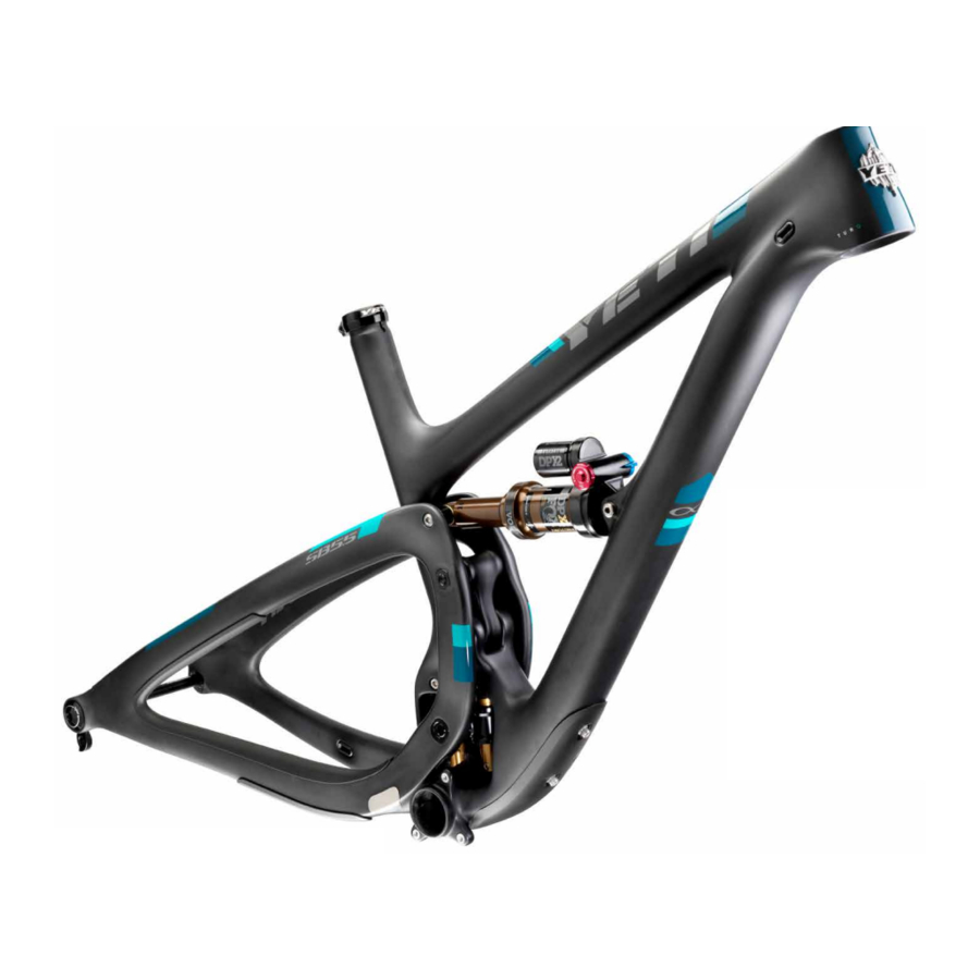
THE LOWDOWN ON THE SB5.5 AND ITS FEATURES
- SWITCH INFINITY TECHNOLOGY PATENTED SUSPENSION SYSTEM
- HIGH MODULUS CARBON FIBER MAIN FRAME AND SWING ARM
- COLLET AXLE SYSTEM ON PIVOTS REDUCES BEARING WEAR
- OPTIMIZED FOR 1X DRIVETRAINS ONLY
- ISCG 05 CHAIN GUIDE MOUNTS
- TAPERED INSET HEAD TUBE (44MM/56MM)
- SUSPENSION BY FOX
- CUSTOM DEBRIS AND CHAIN SLAP GUARDS
- INTERNAL CABLE ROUTING
- INTEGRATED AXLE AND DERAILLEUR HANGER SYSTEM
- The SB5.5 delivers 5.5 inches (140mm) of travel with our patented Switch Infinity Technology. Efficient pedaling performance while still smooth and continuous when the going gets rough.
- High modulus carbon provides a stiff, strong and light weight chassis.
- Colleted pivot axles help create a stiff interface between the front and rear triangles of the frame. Custom Enduro Max sealed bearings keep things moving freely at the pivots.
- The SB5.5 does away with the front derailleur mount, making it a 1x drive specific frame. This increases stiffness in the frame, making the SB5.5 one of the stiffest bikes in our lineup.
- ISCG 05 chain guide mounts are included on the SB5.5 if case you want to go for some extra drivetrain security in the rowdy sections.
- Using our inset head tube on the SB5.5 allows for a larger head tube with more area, increased stiffness, and lower overall ride height without compromising any performance.
- The SB5.5 uses a 2.25 inch stroke, 7.875 inch eye to eye DPX2 EVOL shock, by Fox Racing Shox.
- Custom guards on the seat stay, chain stay and down tube keep things quiet while riding and protect the frame.
- The SB5.5 features internal routing for all cables, making the bike quiet and clean looking as well as reducing cable rub on the paint.
- Dedicated 12 x 148 Boost dropouts and integrated hanger with axle threads for strength, stiffness, ease of hanger and wheel installation.
GEOMETRY

FOX 36 / 160MM FORK
| MD | LG | XL | ||
| A | WHEEL | 29" | 29" | 29" |
| B | REACH | 421 | 442 | 463 |
| C | EFF. TOP TUBE | 601 | 626 | 652 |
| D | STACK | 610 | 624 | 639 |
| E | HEAD TUBE LENGTH | 90 | 105 | 121 |
| F | SEAT TUBE LENGTH | 445 | 483 | 521 |
| G | EFF. SEAT TUBE ANGLE | 73.6 | 73.6 | 73.6 |
| H | HEAD TUBE ANGLE | 66.5 | 66.5 | 66.5 |
| I | MECH. TRAIL | 96.3 | 96.2 | 96.1 |
| J | BB DROP | 23.7 | 23.7 | 23.8 |
| K | EST. BB HEIGHT | 346.2 | 346.2 | 346.2 |
| L | CHAINSTAY LENGTH | 436.9 | 436.9 | 436.9 |
| M | FRONT-CENTER | 730.6 | 757.9 | 785.4 |
| N | WHEELBASE | 1167.7 | 1195.0 | 1222.4 |
| O | STANDOVER | 742.9 | 754.6 | 767.2 |
| P | ALXE TO CROWN | 567.1 | 567.1 | 567.1 |
| Q | FORK OFFSET | 51 | 51 | 51 |
*All measurements are in millimeters
FIT
| MEDIUM | 5'7" (170 CM) - 5'11" (180 CM) |
| LARGE | 5'11" (180 CM) - 6'3" (191 CM) |
| X-LARGE | 6'1" (185 CM) - 6'6" (198 CM) |
KEEP YOUR YETI FRESH AND CLEAN
OVERVIEW
Following these guidelines will help maintain the performance of your bicycle and prevent more serious problems from arising. It is important to remember that service intervals can vary depending on climate, trail conditions and riding frequency. If you are unsure about working on your own bicycle, contact your authorized Yeti Dealer for more information on general bicycle maintenance.
SCHEDULE
| WEEKLY | MONTHLY | 3 MONTHS | ANNUALLY | |||||
| CLEAN AND LUBE CHAIN | • | |||||||
| CHECK TIRE PRESSURE | • | |||||||
| CLEAN BIKE OF MUD AND DEBRIS | • | |||||||
| CHECK BRAKE FUNCTION | • | |||||||
| CHECK SHOCK PRESSURE, IF APPLICABLE | • | |||||||
| CHECK FOR LOOSE BOLTS AND TIGHTEN, IF NECESSARY | • | |||||||
| CHECK HEADSET AND TIGHTEN / LOOSEN, IF NECESSARY | • | |||||||
| THOROUGHLY CLEAN PIVOT POINTS WITH A RAG (DO NOT LUBRICATE) | • | |||||||
| LUBE INFINITY LINK EVERY 40 HRS. (YETI HEAVY MOLYBDENUM GREASE) | • | |||||||
| CHECK / REPLACE BRAKE PADS, IF NECESSARY | • | |||||||
| CHECK TIRES FOR WEAR | • | |||||||
| CHECK SPOKE TENSION AND RETENTION, IF NECESSARY | • | |||||||
| CHECK CHAIN FOR WEAR AND REPLACE IF NECESSARY | • | |||||||
| COMPLETE TUNE-UP PERFORMED BY AN AUTHORIZED YETI DEALER | • | |||||||
TORQUE
Yeti strongly recommends using a torque wrench when assembling your frame. Torque specifications for individual parts on the SB5.5 are listed below, as well as in the step by step assembly instructions later in the manual. For general bicycle maintenance please consult the torque specifications of the component you are adjusting.
KEY TORQUE SPECS
| PART NUMBER | DESCRIPTION | TORQUE (NM) |
| 300030151 | BOLT TI MALE (M6 X 1 X 12MM) | 7 |
| 300030057 | INFINITY LINK BOLTS (M6 X 1) | 12 |
| 300040484 | UPPER LINK COLLET AXLE (M10 X 10) | 3 |
| 300040486 | UPPER LINK COLLET WEDGE (M5 X.8) | 8 |
| 300040483 | LOWER LINK COLLET AXLE (M10 X 10) | 3 |
| 300040486 | LOWER LINK COLLET WEDGE (M5 X.8) | 8 |
| 300040485 | MAIN PIVOT COLLET AXLE (M15 X 1.5) | 3.5 |
| 300040454 | MAIN PIVOT COLLET WEDGE (M8 X 1.25) | 14 |
SHOCK SETUP
YETI TIPS
Inspect your shock for any visible damage. If oil is leaking or you notice any damage to the surfaces or seals, please contact the Fox Racing Shox service center for repair at 800. FOX.SHOX or your local bike shop.
Shock set-up can fluctuate greatly based on the rider. The set-up guide is intended as a base line to get the rider started. Experiment with your settings to find the set-up that works best for you.
We recommend starting out with 30% sag, which is 17.5mm of shock stroke.
TOOLS NEEDED

- Shock Pump
- Metric Tape Measure
- 2.5mm allen wrench
QUICK START GUIDE
| ADJUSTMENT | SETTING |
| BASELINE AIR SPRING SETTING | RIDER WEIGHT (PSI) |
| MEASURED SAG (MM) | 17.5MM |
| REBOUND | 7 CLICKS* |
| COMPRESSION ADJUSTMENT | OPEN |
*All clicks are counted counter-clockwise, rotating from the all the way "in" or clockwise dial position.
- AIR PRESSURE
The main air spring controls sag. For the SB5.5 to ride properly it is important to setup the shock with the correct amount of sag. To increase sag, reduce the main spring air pressure. To reduce sag, increase the main spring air pressure. Always cycle the shock at least 10 times after any pressure adjustment to equalize the EVOL chamber before measuring sag.
![]()
- SAG
The SB5.5 works best with 17.5MM of measured sag. To measure the sag slide the travel indicator (O-Ring) up against the shock body. With a friend supporting the bike and with the compression set "open," sit on the saddle and allow your body weight to compress the shock. Once you have compressed the shock, get off the bike and measure the distance between the shock body and the new position of the travel indicator (O-Ring). This is your sag.
![]()
- REBOUND
Rebound is adjusted using the red knob located on the drive side. Clockwise will slow the rebound, counter clockwise will speed it up. Rebound needs to be tuned to rider preference and air spring pressure. This may take some experimentation to dial in. Too slow and the bike will feel like it is not ready for the next bump. Too fast and it will feel like the bike is bucking you off after an impact.
![]()
- COMPRESSION
The blue lever on the non drive side has 3 positions: Open, Medium and Firm. For our bikes, unless you are on pavement on the way to the trail, we recommend using the "open" setting. The Switch Infinity design will do the rest! Low-speed compression is adjusted using a 2.5mm allen wrench. It is located in the center of the blue 3-position lever. There are 10 clicks on this adjustment. This adjustment only effects the the "open" position.
![]()


DERAILLEUR HANGER INSTALL
YETI TIPS
NOTE: The hanger cap is REVERSE THREADED. Be careful not to strip out the Hanger tool faces. The cap is marked with a tighten direction arrow.
Inspect the frame around the hanger seat for any suspicious damage any time you replace a hanger, especially if you are replacing it due to damage.

TOOLS NEEDED
- 6mm Allen key
- Grease
- HANGER SEAT
Lightly grease the outside surface of the hanger where it interfaces with the frame. The hanger will fit into its space on the inside of the swing arm and should press easily into the frame.
![]()
- HANGER CAP SEAT
Lightly grease the threads on the hanger cap. The hanger cap REVERSE threads into the hanger from the outside of the swing arm. Hand thread the cap into the hanger.
![]()
- TIGHTENING
Using a 6mm allen key, tighten the hanger cap into the hanger. REMEMBER, it is REVERSE THREADED. Follow the "Tighten" arrow on the cap. Finish tightening with a torque wrench if available.
*Torque to 80 in/lbs (9Nm)
![]()
- COMPLETED
The installed hanger and cap should look like this, sitting flush against the frame on both the inside and outside of the swing arm. If the hanger or cap are not sitting flush against the frame, remove them and inspect the frame surfaces for debris as well as the threads for damage.
![]()


CABLE SETUP
The SB5.5 uses internally routed full length cable housing. By using full cable housing, we have eliminated break points in the line of your shifter housing. This allows for better overall shifting performance by reducing the entrance of unwanted elements such as sweat and sediment. By routing that housing internally we add to the protection form the elements and clean up the lines of the bike. No more zip ties to snag your shorts on and no more loose housing rattling around on your paint.
Do not remove any of the housing guide tubes that are installed in your new frame and swing arm. They will be used to pull your housing through the frame. If you are replacing used housing, use the old housing to pull your new housing through the frame.
If you don't have the guide tubes or old housing you can fish the housings through the frame, but it will be much easier to use an internal cable routing tool.

The failure to properly route shifter housing can cause malfunction of the shift mechanism and unexpected shifting of gears.
REAR BRAKE AND DERAILLEUR
Your rear brake and shifter housing should run parallel around the left side of the head tube. Run the shifter housing and the brake housing into the individual ports at the head tube and thread them down into the down tube toward the exit ports above the Infinity Link. The shift housing comes out of the port on the drive side and goes immediately into the corresponding port on the swing arm. The brake housing does the same on the non-drive side.

NOTE: Use rubbing alcohol to help the housing pass through the grommets as you thread it through the frame.
Starting at the back of the bike and working forward will be necessary for some brake systems.
REAR DERAILLEUR CONTINUED
The rear derailleur housing will exit the swing arm via the port on the upper side of the seat stay right above the rear derailleur. Create a gentle curve to the derailleur and adjust to the manufacturers specifications.

REAR BRAKE CONTINUED
The rear brake housing exits the swing arm on the inside of the chain stay and goes directly up to the caliper. If your caliper allows, adjust the housing attachment angle to reduce the bend in the cable as much as possible.

INTERNALLY ROUTED SEAT POST
The SB5.5 is designed to use an internally routed dropper post. The housing should be routed from the post forward. Guide your housing through the seat tube and into the down tube use the guide tube installed in our new frames, or use the old housing if you are replacing the line on a used bike. The line should exit the down tube at the head tube on the drive side and curve around the head tube to the lever on the left side of the bar. If you are mounting your lever on the right side, you would simply route that housing over to the right. If you do route to the right we recommend placing some clear vinyl in front of the port to prevent cable rub.

FRAME ASSEMBLY
YETI TIPS
Make sure your tools are in good condition. A worn allen key can round the hex on a bolt not allowing for proper torque.
Torque settings are listed throughout the instructions. It is important to prep all bolt threads. The instructions denote whether to use a Loctite compound or grease.

Service on Yeti bicycles requires special knowledge and tools. Yeti Cycles recommends that all service and repairs be performed by an authorized Yeti Dealer
TOOLS NEEDED

- 2.5mm allen key
- 5mm allen keys
- 4mm allen keys
- 10mm allen key
- Guide pin tool (Or two)
- Torque wrench
- Grease
- Blue (242) Loctite
- All the parts you'll need to get your SB5.5 frame assembled. Please refer to the exploded view later in this manual for more information.
![]()
- Slip washers onto and apply blue (242) Loctite to the 4 bolts that secure the Switch Infinity Link to the frame. Insert them into their place and hang the black fitting washers from them. Place washers with the flat side flush to the frame and opening.
![]()
- Insert the Infinity Link from the non-drive side. The Infinity logo should be up and the Fox logos facing the non-drive side. Rock the link into place capturing the black fitting washers. Make sure that they have not slipped or rotated. The flat end of the fitting washers must be facing the opening in the frame and they must nestle into the Infinity Link stanchions.
![]()
- While holding the link in place lightly tighten the bolts. You want them to snug so that the link does not move and so that the fitting washers are fully captured, but don't try to torque them by hand! Finish the job with a torque wrench.
*Torque to 12 Nm
![]()
- Lightly grease the bearing surfaces on your link.
![]()
- Place the bearing race extender washers (300020049) on the lower link bearings. There should be just enough grease there to hold the washers in place.
![]()
- Insert the lower end of the link into the frame with the bearing race extending washers in place. Gently rest the link upright in the frame.
![]()
- Using one hand, align the link and press the lightly greased pivot axle (300040483) through. This will hold the link in place while you prep the pivot axle nut.
![]()
- Insert the collet axle nut (300030287) in the corresponding keyed hole and thread the axle in using a 5mm allen wrench. This acts like a headset and is meant to preload the bearings.
*Torque: 3 Nm
![]()
- Install the well greased lower link collet wedge. (300040486) Tighten with a 4mm allen wrench and finish with a torque wrench.
*Torque: 8 Nm
![]()
- Your lower link pivot is now complete. Wipe any excess grease from the pivot axle area now and double check your torques. This is more difficult later in the process.
![]()
- Place the upper link bearing race extender washers onto the upper link bearings. The grease should hold them in place.
![]()
- Grease the main pivot collet axle (300040485), including the threads.
![]()
- Slide the swingarm over the infinity link and insert the main pivot collet axle from the non drive side. You may need to use a guide pin from the drive side to help align the bearing spacer in the link.
![]()
- Insert the lightly greased main pivot axle nut (300030285) into the corresponding keyed hole in the swingarm and thread the main pivot collet axle into it. Using a 10mm allen wrench, tighten the main pivot collet axle.
*Torque: 3.5 Nm
![]()
- Grease the upper link pivot collet axle (300040484). Push the pivot axle through the swingarm and the upper link bearings from the non drive side. You may want to use a guide pin to help align the bearing spacer.
![]()
- Insert the lightly greased upper link pivot axle nut (300030286) into the keyed hole in the swingarm and, using a 5mm allen wrench, thread the pivot axle into the nut. Using a piece of foam or bubble wrap behind the link will help protect your paint until the shock is installed.
*Torque to 3 Nm
![]()
- Grease and install the main pivot collet wedge with a 5mm allen wrench. Be sure to grease both the threads and the collet wedge.
*Torque to 14 Nm
![]()
- Grease and install the upper link collet wedge with a 4mm allen wrench. Be sure to grease both the threads and the collet wedge.
*Torque: 8 Nm
![]()
- Wipe up any excess grease around the collet wedge bolts and remove the foam/bubble wrap from behind the link in preparation for installing the shock.
![]()
- Slide the rear of the shock into the swingarm, align the shock eyelet and secure with a guide pin.
![]()
- Align the front shock eyelet to the mounting points on the front triangle and secure with a guide pin.
![]()
- Place the 8.5mm washer (300030069) on the front shock mounting pin (300030262) and lightly grease the pin shaft.
![]()
- Slide the shock mounting pin over the guide pin and push it through the frame and the shock.
![]()
- Place the 6.5mm washer (300030062) over a Male Ti bolt (300030151). Apply Blue LocTite to the threads. Using two 5mm allen wrenches tighten the male bolt into the shock pin.
*Torque to 7 Nm
![]()
- Tighten a malel Ti bolt (300030151 ) into the rear shock pin (300030288), ensuring that it is fully threaded into the pin. Slide a 8.5mm washer (300030069) over the pin and lightly grease the pin shaft.
![]()
- Slide the rear shock pin over the guide pin and push it through the swingarm and shock.
![]()
- Place the 6.5mm washer (300030062) over a Male Ti bolt (300030151). Apply Blue LocTite to the threads. Using two 5mm allen wrenches tighten the male bolt into the shock pin.
*Torque to 7 Nm
![]()


EXPLODED VIEW

EXPLODED VIEW PARTS LIST
| ITEM# | PART # | DESCRIPTION | QTY |
| 1 | N/A | SB5.5 FRONT TRIANGLE ASSEMBLY | |
| 1.1 | N/A | SB5.5 FRONT TRIANGLE | 1 |
| 1.2 | 300070006 | ICE AXE HEAD BADGE | 1 |
| 1.3 | 300060072 | YETI SEAT CLAMP STANDARD | 1 |
| 1.4 | 300040491 | SLOT PORT GROMMET | 5 |
| 1.5 | 300030010 | BOLT-CAP H20 (M5 X 0.8 X 16MM) | 2 |
| 1.6 | 300030148 | WASHER 5.1X8.9X1MM | 2 |
| 1.7 | 400100134 | SB5.5 DT PROTECTOR | 1 |
| 2 | N/A | SB5.5 SWING ARM ASSEMBLY | |
| 2.1 | N/A | SB5.5 SWING ARM | 1 |
| 2.2 | 300060073 | 12X148 HANGER STD KIT GEN3 | 1 |
| 2.2.1 | 300060074 | 12X148 HANGER STANDARD GEN3 | 1 |
| 2.2.2 | 300060075 | 12X148 HANGER CAP GEN3 | 1 |
| 2.3 | 300040491 | SLOT PORT GROMMET | 4 |
| 2.4 | 400100135 | SB5.5 CS/SS PROTECTOR | 1 |
| 2.5 | 400100136 | SB5.5 CHAIN SUCK GUARD | 1 |
| 2.6 | 400100137 | SB5.5 CS LOWER PROTECTOR | 1 |
| 3 | 200020201 | FOX LINEAR BEARING 74.0MM ASSEMBLY | |
| 4 | N/A | SHOCK ASSEMBLY SB5.5 | |
| 4.1 | N/A | FOX FLOAT DPS 7.5 X 2.25 | 1 |
| 4.2 | 214-09-035 | FOX MOUNT KIT 44.856MM (45MM) | 1 |
| 4.3 | 214-09-006 | FOX MOUNT KIT 21.84MM (22MM) | 1 |
| 5 | N/A | SB5.5 ASSEMBLY PARTS | |
| 5.1A | 200020268 | SB5.5 ALLOY LINK ASSEMBLY | 1 |
| 5.1C | 200020249 | SB5.5 CARBON LINK ASSEMBLY | 1 |
| 5.1.1A | 300040497 | SB5.5 ALLOY LINK | 1 |
| 5.1.1C | 300040494 | SB5.5 CARBON LINK | 1 |
| 5.1.2 | 300020050 | BEARING 6900-2RS-MAX 22X10X6 | 4 |
| 5.1.3 | 300030281 | SPACER 10MM X 29.0MM | 1 |
| 5.1.4 | 300030282 | SPACER 10MM X 6.0MM | 1 |
| 5.2 | 300020049 | INNER RACE EXTENDER 10MM | 4 |
| 5.3 | 300040484 | COLLET AXLE 10X53.5X13.0 M10X1.0 | 1 |
| 5.4 | 300040486 | COLLET WEDGE SUB-ASSEMBLY 10MM | 2 |
| 5.4.1 | 300030284 | COLLET BOLT M5X.8 | 1 |
| 5.4.2 | 300030283 | COLLET WEDGE 10MM | 1 |
| 5.4.3 | 300040482 | SPIRAL RETAINING RING | 1 |
| 5.5 | 300030286 | COLLET NUT M10X1X12MM | 1 |
| 5.6 | 300040483 | COLLET AXLE 10X30.5X9.0 M10X1.0 | 1 |
| 5.7 | 300030287 | COLLET NUT M10X1X8MM | 1 |
| 5.8 | 300040485 | COLLET AXLE 15X52.5SX13.0T M15X1.5 | 1 |
| 5.9 | 300040454 | COLLET WEDGE SUB-ASSEMBLY GEN2 | 1 |
| 5.9.1 | 300030268 | COLLET BOLT M8X1.25 | 1 |
| 5.9.2 | 300030267 | COLLET WEDGE 15MM | 1 |
| 5.9.3 | 300040450 | SPIRAL RETAINING RING | 1 |
| 5.10 | 300030285 | COLLET NUT M15X1.5X12MM | 1 |
| 5.11 | 300030262 | BOLT TI FEMALE 8.0X31.0MM GEN2 | 1 |
| 5.12 | 300030069 | WASHER 8.5X12.5X0.5 MM | 2 |
| 5.13 | 300030151 | BOLT TI MALE M6X12.0MM | 3 |
| 5.14 | 300030062 | WASHER 6.5X12.5X0.5 MM | 2 |
| 5.15 | 300030288 | BOLT TI STUD 8.0X54.0MM | 1 |
| 5.16 | 300030057 | BOLT-CAP (M6 X 1 X 20 MM) | 4 |
| 5.17 | 300030214 | WASHER (10X6.2X1MM) | 4 |
| 5.18 | 300040474 | BLANK PORT GROMMET | 1 |
REBUILD KIT
| PART # | DESCRIPTION | QTY |
| 200020272 | SB5.5 MASTER REBUILD KIT | |
| 300020049 | BEARING RACE EXTENDER 23X10 | 4 |
| 300020050 | BEARING 6900 2RSMAX 22X10X6 | 4 |
| 300030010 | BOLT-CAP- M5X.8X16 - H20 BOLT | 2 |
| 300030057 | BOLT CAP M6X1X20 | 4 |
| 300030062 | WASHER SS 6.5MM ID 12.5 OD.5M | 2 |
| 300030069 | WASHER SS 8.5MM ID 12.5MM OD | 2 |
| 300030148 | WASHER SS 5.1MM ID 8.9 OD 1MM | 2 |
| 300030151 | BOLT TI MALE M6X 12MM | 3 |
| 300030214 | WASHER 10 X 6.2 X 1 | 4 |
| 300030262 | BOLT TI FEMALE 8.0X31.0MM GEN2 | 1 |
| 300030281 | SPACER 10X29.0MM | 1 |
| 300030282 | SPACER 10X6.0MM | 1 |
| 300030285 | COLLET AXLE NUT M15X1.5X12 | 1 |
| 300030286 | COLLET AXLE NUT M10X1X12 | 1 |
| 300030287 | COLLET AXLE NUT M10X1X8 | 1 |
| 300030288 | STUD TI FEMALE 8X54.0MM | 1 |
| 300040454 | COLLET-WEDGE ASSEMBLY GEN2 | 1 |
| 300040474 | BLANK PORT GROMMET | 1 |
| 300040483 | AXLE COLLET 10X30.5SX9T | 1 |
| 300040484 | AXLE COLLET 10X53.5SX13T | 1 |
| 300040485 | AXLE COLLET 15X52.5SX13T | 1 |
| 300040486 | COLLET WEDGE ASSEMBLY - M10 | 2 |
| 300040491 | SLOT PORT GROMMET | 9 |
| 200020253 | SB5.5 BEARING REBUILD KIT | |
| 300020050 | BEARING 6900 2RSMAX | 4 |
| 300030281 | SPACER 10X29.0MM | 1 |
| 300030282 | SPACER 10X6.0MM | 1 |
| 200020273 | SB5.5 HARDWARE REBUILD KIT | |
| 300020049 | BEARING RACE EXTENDER 23X10 | 4 |
| 300030010 | BOLT-CAP- M5X.8X16 - H20 BOLT | 2 |
| 300030057 | BOLT CAP M6X1X20 | 4 |
| 300030062 | WASHER SS 6.5MM ID 12.5 OD.5M | 2 |
| 300030069 | WASHER SS 8.5MM ID 12.5MM OD. | 2 |
| 300030148 | WASHER SS 5.1MM ID 8.9 OD 1MM | 2 |
| 300030151 | BOLT TI MALE M6X12MM | 3 |
| 300030214 | WASHER 10 X 6.2 X 1 | 4 |
| 300030262 | BOLT TI FEMALE 8.0X31.0MM GEN2 | 1 |
| 300030285 | COLLET AXLE NUT M15X1.5X12 | 1 |
| 300030286 | COLLET AXLE NUT M10X1X12 | 1 |
| 300030287 | COLLET AXLE NUT M10X1X8 | 1 |
| 300030288 | STUD TI FEMALE 8X54.0MM | 1 |
| 300040454 | COLLET-WEDGE ASSEMBLY GEN2 | 1 |
| 300040483 | AXLE COLLET 10X30.5SX9T | 1 |
| 300040484 | AXLE COLLET 10X53.5SX13T | 1 |
| 300040485 | AXLE COLLET 15X52.5SX13T | 1 |
| 300040486 | COLLET WEDGE ASSEMBLY - M10 | 2 |
| 200020231 | FOX LINEAR BEARING 74.0MM SB5.5 | |
| 200020201 | FOX LINEAR BEARING 74.0MM ASSE | 1 |
| 300030057 | BOLT CAP M6X1X20 | 4 |
| 300030214 | WASHER 10 X 6.2 X 1 | 4 |
| 400100146 | PROTECTOR KIT SB5.5 | |
| 400100134 | PROTECTOR SB5.5 DOWN TUBE | 1 |
| 400100135 | PROTECTOR SB5.5 CHAIN STAY/SEAT STAY | 1 |
| 400100136 | PROTECTOR SB5.5 CHAIN SUCK | 1 |
| 400100137 | PROTECTOR SB5.5 LOWER CHAIN STAY | 1 |
| 400100146 | SB5.5 PROTECTOR DECAL KIT | |
| 200020275 | SB5.5 CABLE GUIDE KIT | |
| 300040474 | BLANK PORT GROMMET | 1 |
| 300040491 | SLOT PORT GROMMET | 9 |
| SB5.5 MISCELLANEOUS PARTS | ||
| 200020263 | LINK SB5.5 W/BEARING GLOSS | N/A |
| 200020249 | LINK SB5.5 W/BEARING MATTE | N/A |
| 300060073 | 12X148 HANGER STD KIT BLACK | N/A |
| 300060077 | 12X148 HANGER STD KIT TURQUOISE | N/A |
YETI CYCLES
621 Corporate Circle, Unit B
Golden, CO 80401
(p) 303-278-6909
(f) 303-278-6906
www.yeticycles.com
BUSINESS HOURS
Monday-Friday
8AM-11:30AM, 1:00PM-5:30PM
(Mountain Time)
Documents / Resources
References
Download manual
Here you can download full pdf version of manual, it may contain additional safety instructions, warranty information, FCC rules, etc.
Advertisement


Need help?
Do you have a question about the SB5.5 and is the answer not in the manual?
Questions and answers