Advertisement
- 1 SAFETY
- 2 SPECIFICATION
- 3 INSTALLATION
- 4 OPERATION
- 5 MAINTENANCE
-
6
TROUBLESHOOTING
- 6.1 The electrode holder becomes very hot
- 6.2 Excessive spatter in STICK welding
- 6.3 Poor starting
- 6.4 Black area along weld bead
- 6.5 Unstable Arc
- 6.6 Arc wanders
- 6.7 HF TIG doesn't initiate an arc
- 6.8 Tungsten burning away quickly
- 6.9 Contaminated tungsten
- 6.10 Poor starting
- 6.11 Stick electrode "blasts Off" when arc is struck
- 6.12 Electrode "stick" in weld puddle
- 7 Documents / Resources

SAFETY
PLEASE EXAMINE THE PACKING BOX AND EQUIPMENT FOR DAMAGE IMMEDIATELY
When this equipment is shipped, the title passes to the purchaser upon receipt by the carrier. Consequently, claims for material damaged in shipment must be filed by the purchaser against the transportation company when the shipment is received.
SAFETY DEPENDS ON YOU
YESWELDER arc welding and cutting equipment are designed and built with safety. However, your overall safety can be increased by proper installation and thoughtful operation on your part. DO NOT INSTALL, OPERATE OR REPAIR THIS EQUIPMENT WITHOUT READING THIS MANUAL AND THE SAFETY PRECAUTIONS CONTAINED THROUGHOUT. And most importantly, think before you act and be careful.

This statement appears where the information must be followed precisely to avoid serious personal injury or loss of life.

This statement appears where the information must be followed to avoid minor personal injury or damage to this equipment.
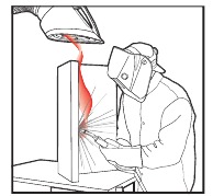
KEEP YOUR HEAD OUT of THE FUMES.
DON'T get too close to the arc. Use corrective lenses if necessary to stay a reasonable distance from the arc.
READ and obey the Safety Data Sheet (SDS) and the warning label on all welding materials containers.
USE ENOUGH VENTILATION or exhaust at the arc, or both, to
keep the fumes and gases from your breathing zone and the general area.
IN A LARGE ROOM OR OUTDOORS, natural ventilation may be adequate if you keep your head out of the fumes (See below).
USE NATURAL DRAFTS or fans to keep the fumes away from your face.
If you develop unusual symptoms, see your supervisor. Perhaps the welding atmosphere and ventilation system should be checked.
WEAR CORRECT EYE, EAR & BODY PROTECTION

PROTECT your eyes and face with welding helmet properly fitted and with proper grade of filter plate (See ANSI Z49.1).
PROTECT your body from welding spatter and arc flash with protective clothing including woolen clothing, flame-proof apron and gloves, leather leggings, and high boots. PROTECT others from spatter, flash, and glare with protective screens or barriers.
IN SOME AREAS, protection from noise may be appropriate.
BE SURE protective equipment is in good condition. Also, wear safety glasses in work area AT ALL TIMES.

SPECIAL SITUATIONS
DO NOT WELD OR CUT containers Or materials which previously had been in contact with hazardous substances unless they are properly cleaned DO NOT WELD OR CUT painted or plated parts unless special precautions with ventilation have been taken They can release highly toxic fumes or gases
Additional precautionary measures: PROTECT compressed gas cylinders from excessive heat, mechanical shocks, and arcs; fasten cylinders so they cannot fall BE SURE cylinders are never grounded or part of an electrical circuit REMOVE all potential fire hazards from welding area ALWAYS HAVE FIRE FIGHTING EQUIPMENT READY FOR IMMEDIATE USE AND KNOW HOW TO USE IT.

CALIFORNIA PROPOSITION 65 WARNINGS
Breathing diesel engine exhaust exposes you to chemicals known to the State of California to cause cancer and birth defects, or other reproductive harm.
- Always start and operate the engine in a well-ventilated area
- If in an exposed area, vent the exhaust to the outside.
- DO not modify or tamper with the exhaust system
- Do not idle the engine except as necessary
For more information go to www.P65warnings.ca.gov/diesel
This product, when used for welding or cutting, produces fumes or gases which contain chemicals known to the State of California to cause birth defects and, in some cases, cancer. (California Health & Safety Code § 25249.5 et seq.)
Cancer and Reproductive Harm www.P65warnings.ca.gov
ARC WELDING CAN BE HAZARDOUS. PROTECT YOURSELF AND OTHERS FROM POSSIBLE SERIOUS INJURY OR DEATH. KEEP CHILDREN AWAY. PACEMAKER WEARERS SHOULD CONSULT WITH THEIR DOCTOR BEFORE OPERATING.
Read and understand the following safety highlights. For additional safety information, it is strongly recommended you download free PDF of Standard ANSI Z49.1 from the American Welding Society. https://www.aws.org/library/doclib/AWS-Z49-2021.pdf
BE SURE THAT ALL INSTALLATION, OPERATION, MAINTENANCE AND REPAIR PROCEDURES ARE PERFORMED ONLY BY QUALIFIED INDIVIDUALS.
 FOR ENGINE POWERED EQUIPMENT.
-
- Turn the engine off before troubleshooting and maintenance work unless the maintenance work requires it to be running.
![]()
- Operate engines in open, well ventilated areas or vent the engine exhaust fumes outdoors.
- Do not add the fuel near an open flame welding arc or when the engine is running. Stop the engine and allow it to cool before refueling to prevent spilled fuel from vaporizing on contact with hot engine parts and igniting. Do not spill fuel when filling tank.
![]()
- Keep all equipment safety guards, covers and devices in position and in good repair. Keep hands, hair, clothing and tools away from Vbelts, gears, fans and all other moving parts when starting, operating or repairing equipment.
![]()
- In some cases it may be necessary to remove safety guards to perform required maintenance. Remove guards only when necessary and replace them when the maintenance requiring their removal is complete. Always use the greatest care when working near moving parts.
- Do not put your hands near the engine fan. Do not attempt to override the governor or idler by pushing on the throttle control rods while the engine is running.
If fuel is spilled, wipe it up and do not start engine until fumes have been eliminated. - To prevent accidentally starting gasoline engines while turning the engine or welding generator during maintenance work, disconnect the spark plug wires, distributor cap or magneto wire as appropriate.
- To avoid scalding, do not remove the radiator pressure cap when the engine is hot.
![]()
- Turn the engine off before troubleshooting and maintenance work unless the maintenance work requires it to be running.


 ELECTRIC AND MAGNETIC FIELDS MAY BE DANGEROUS
-
- Electric current flowing through any conductor causes localized Electric and Magnetic Fields (EMF). Welding current creates EMF fields around welding cables and welding machines
- EMF fields may interfere with some pacemakers, and welders having a pacemaker should consult their physician before welding.
- Exposure to EMF fields in welding may have other health effects which are now not known.
- All welders should use the following procedures in order to minimize exposure to EMF fields from the welding circuit:
- Route the electrode and work cables together - Secure them with tape when possible.
- Never coil the electrode lead around your body.
- Do not place your body between the electrode and workcables. If the electrode cable is on your right side, the work cable should also be on your right side.
- Connect the work cable to the workpiece as close as possible to the area being welded.
- Do not work next to welding power source.
ELECTRIC SHOCK CAN KILL.

-
- The electrode and work (or ground) circuits are electrically "hot" when the welder is on. Do not touch these "hot" parts with your bare skin or wet clothing. Wear dry, hole-free gloves to insulate hands.
- Insulate yourself from work and ground using dry insulation. Make certain the insulation is large enough to cover your full area of physical contact with work and ground.
In addition to the normal safety precautions, if welding must be performed under electrically hazardous conditions (in damp locations or while wearing wet clothing; on metal structures such as floors, gratings or scaffolds; when in cramped positions such as sitting, kneeling or lying, if there is a high risk of unavoidable or accidental contact with the workpiece or ground) use the following equipment:- Semiautomatic DC Constant Voltage (Wire) Welder.
- DC Manual (Stick) Welder.
- AC Welder with Reduced Voltage Control.
- In semiautomatic or automatic wire welding, the electrode, electrode reel, welding head, nozzle or semiautomatic welding gun are also electrically "hot".
- Always be sure the work cable makes a good electrical connection with the metal being welded. The connection should be as close as possible to the area being welded.
- Ground the work or metal to be welded to a good electrical (earth) ground.
- Maintain the electrode stinger, work clamp, welding cable and welding machine in good, safe operating condition. Replace damaged insulation.
- Never dip the electrode in water for cooling.
- Never simultaneously touch electrically "hot" parts of electrode stingers connected to two welders because voltage between the two can be the total of the open circuit voltage of both welders.
- When working above floor level, use a safety belt to protect yourself from a fall should you get a shock.
- Also see Items 6.c. and 8.
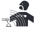
ARC RAYS CAN BURN.

-
- Use a shield with the proper filter and cover plates to protect your eyes from sparks and the rays of the arc when welding or observing open arc welding. Welding shield and filter lens should conform to ANSI Z87. I standards.
- Use suitable clothing made from durable flame-resistant material to protect your skin and that of your helpers from the arc rays.
- Protect other nearby personnel with suitable, nonflammable screening and/or warn them not to watch the arc nor expose themselves to the arc rays or to hot spatter or metal.
FUMES AND GASES CAN BE DANGEROUS.

-
- Welding may produce fumes and gases hazardous to health. Avoid breathing these fumes and gases. When welding, keep your head out of the fume. Use enough ventilation and/or exhaust at the arc to keep fumes and gases away from the breathing zone. When welding hardfacing (see instructions on container or SDS) or on lead or cadmium plated steel and other metals or coatings which produce highly toxic fumes, keep exposure as low as possible and within applicable OSHA PEL and ACGIH TLV limits using local exhaust or mechanical ventilation unless exposure assessments indicate otherwise. In confined spaces or in some circumstances, outdoors, a respirator may also be required. Additional precautions are also required when welding on galvanized steel.
- The operation of welding fume control equipment is affected by various factors including proper use and positioning of the equipment, maintenance of the equipment and the specific welding procedure and application involved. Worker exposure level should be checked upon installation and periodically thereafter to be certain it is within applicable OSHA PEL and ACGIH TLV limits.
- Do not weld in locations near chlorinated hydrocarbon vapors coming from degreasing, cleaning or spraying operations. The heat and rays of the arc can react with solvent vapors to form phosgene, a highly toxic gas, and other irritating products.
- Shielding gases used for arc welding can displace air and cause injury or death. Always use enough ventilation, especially in confined areas, to insure breathing air is safe.
- Read and understand the manufacturer's instructions for this equipment and the consumables to be used, including the Safety Data Sheet (SDS) and follow your employer's safety practices. SDS forms are available from your welding distributor or from the manufacturer.
- Also see item 1.b.
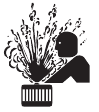
WELDING AND CUTTING SPARKS CAN CAUSE FIRE OR EXPLOSION.
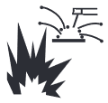
-
- Remove fire hazards from the welding area. If this is not possible, cover them to prevent the welding sparks from starting a fire. Remember that welding sparks and hot materials from welding can easily go through small cracks and openings to adjacent areas. Avoid welding near hydraulic lines. Have a fire extinguisher readily available.
- Where compressed gases are to be used at the job site, special precautions should be used to prevent hazardous situations. Refer to "Safety in Welding and Cutting" (ANSI Standard Z49.1) and the operating information for the equipment being used.
- When not welding, make certain no part of the electrode circuit is touching the work or ground. Accidental contact can cause overheating and create a fire hazard.
- Do not heat, cut or weld tanks, drums or containers until the proper steps have been taken to insure that such procedures will not cause flammable or toxic vapors from substances inside. They can cause an explosion even though they have been "cleaned". For information, purchase "Recommended Safe Practices for the Preparation for Welding and Cutting of Containers and Piping That Have Held Hazardous Substances", AWS F4.1 from the American Welding Society (see address above).
- Vent hollow castings or containers before heating, cutting or welding. They may explode.
- Sparks and spatter are thrown from the welding arc. Wear oil free protective garments such as leather gloves, heavy shirt, cuffless trousers, high shoes and a cap over your hair. Wear ear plugs when welding out of position or in confined places. Always wear safety glasses with side shields when in a welding area.
- Connect the work cable to the work as close to the welding area as practical. Work cables connected to the building framework or other locations away from the welding area increase the possibility of the welding current passing through lifting chains, crane cables or other alternate circuits. This can create fire hazards or overheat lifting chains or cables until they fail.
- Also see item 1.c.
- Read and follow NFPA 51B "Standard for Fire Prevention During Welding, Cutting and Other Hot Work", available from NFPA, 1 Batterymarch Park, PO box 9101, Quincy, MA 022690-9101.
- Do not use a welding power source for pipe thawing.
CYLINDER MAY EXPLODE IF DAMAGED.

-
- Use only compressed gas cylinders containing the correct shielding gas for the process used and properly operating regulators designed for the gas and pressure used. All hoses, fittings, etc. should be suitable for the application and maintained in good condition.
- Always keep cylinders in an upright position securely chained to an undercarriage or fixed support.
- Cylinders should be located:
- Away from areas where they may be struck or subjected to physical damage.
- A safe distance from arc welding or cutting operations and any other source of heat, sparks, or flame.
- Never allow the electrode, electrode stinger or any other electrically "hot" parts to touch a cylinder.
- Keep your head and face away from the cylinder valve outlet when opening the cylinder valve.
- Valve protection caps should always be in place and hand tight except when the cylinder is in use or connected for use.
- Read and follow the instructions on compressed gas cylinders, associated equipment, and CGA publication P-l, "Precautions for Safe Handling of Compressed Gases in Cylinders," available from the Compressed Gas Association, 14501 George Carter Way Chantilly, VA 20151.
FOR ELECTRICALLY POWERED EQUIPMENT.

-
- Turn off the power using the disconnect switch at the fuse box before working on the equipment.
- Install equipment in accordance with the U.S. National Electrical Code, all local codes and the manufacturer's recommendations.
- Ground the equipment following the U.S. National Electrical Code and the manufacturer's recommendations.
SPECIFICATION
GENERAL DESCRIPTION
Unique electric structure and air channel design in this series of machines can speed up the heat rejection of the power device as well as improving the duty cycles of the machines The unique heat rejection efficiency of the air channel can effectively prevent the power devices and control circuits from being damaged by the dust absorbed by the fan, and the reliability of the machine is greatly improved thereby
The whole machine is in form of coherent streamline, the front and rear panels are naturally integrated via large-radian transition manner. The front panel and the rear panel of the machine and the handle are coated with rubber oil, so the machine has soft texture, good hand feeling, and seems warm and pleasant.
This is a digital inverter DC pulse TIG welding machine with perfect function, excellent performance and advanced technology. It has various welding functions such as SMAW, DC TIG, pulsed TIG and TIG spot welding (DC or pulsed), etc, and it can be widely used in fine welding of various metals. The foresighted design and advanced and mature technologies of this machine would protect users' investment to the maximum extent
- Perfect auto-protection function
Perfect automatic protection function is available for this machine When the mains voltage fluctuates greatly, welding will stop automatically, and the error information will be displayed. After the mains voltage becomes stable, welding will recover automatically When overcurrent or overheating occurs, the machine will also stop working automatically with the error information displayed Such comprehensive protection function greatly improves the lifespan of the machine.
- Good consistency and stable performance
This machine adopts intelligent digital control, so it is insensitive to the change of parameters of components. That is, the performance of welding machine will not be affected by the change of the parameters of certain components. Besides, it is insensitive to the change of the working environment such as temperature and humidity, etc. Therefore, the consistency and stability of digital con trol welder is better than that of traditional welder
- Parameter easy to adjust
Generally speaking, for a welding machine with analogue circuit control or with analogue circuit & digital circuit control, the adjustment of most parameters should be achieved through the corresponding circuit, so if more parameters to be adjusted, the circuit would be more complicated and more difficult to be achieved However, for a welding machine with intelligent digital control, the adjustment of parameters is much easier and more accurate, because its main function is achieved through software. - User-friendly interface
This machine adopts graphic language interface, which is simple, vivid, intelligible, and convenient for users' operation
- Remote control available
The machine offers two remote control modes, namely torch control mode and foot control mode, which can meet different application requirements of users
PACKAGING DETAILS
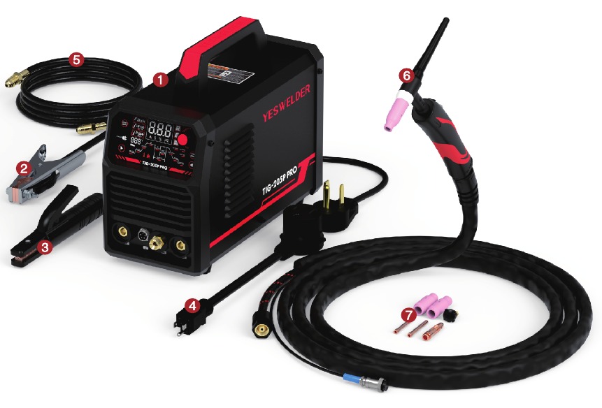
- Welder
- Ground Clamp
- Electrode Holder
- 220V to 1IOV Adapter
- Argon Gas Hose
- WP-17 TIG Torch
- TIG Torch Consumables
TECHNICAL SPECIFICATIONS

POWER SOURCE DIMENSIONS AND WEIGHT
4.85kg(10.71bs)
355X155X240mm (13.98X6.1 X9.45in)

INSTALLATION, SIZE, AND WEIGHT of TIG TORCH

INSTALLATION

ELECTRIC SHOCK CAN KILL.

- Only qualified personnel should perform this installation.
- Only personnel reading and understanding the TIG-205P PRO Operator's Manual should install and operate this equipment.
- The machine must be plugged into a grounded receptacle per national, local, or other applicable electrical codes.
- The TIG-205P PRO power switch should be in the OFF ("O") position when installing the work cable and gun and connecting the power cord to input power.
SELECT PROPER LOCATION
Locate the TIG-205P PRO in a dry place with free clean air circulation to minimize the chance of dirt accumulation that can block air passages and cause overheating
STACKING
TIG.205P PRO cannot be stacked
TILTING
The machine should be placed on a secure, level surface or a recommended cart The equipment may topple over if this requirement is not followed.
Note:
- Please install the machine strictly according to the following steps
- Turn off the power supply switch before any electric connection operation
- The housing protection grade of this machine is IP21S, so do not use it in rain.
- Connect the power input terminal (ACI 10/220V INPUT) on the back panel of the machine to provisions of the Voltage and with a power cord of appropriate specification throng a fuse with a capacity of 50A or more
Locate the welding source near the socket, and keep it well ventilated To ensure good dissipation, the space around the weld ing source should not be less than 250mm
Please protect the circuit with delay fuse of corresponding specifications to ensure normal work.
Grounding requirements:
In order to ensure normal work and personal safety and reduce the EMI, the welding source should be grounded reliably.
OUTPUT CONNECTIONS
CONNECTING TORCH AND WORK LEAD
TIG:

- Connect the TIG torch correctly according to Fig 9-1 Connect the connector of the TIG torch to the "
![]() " connector on the machine, and tighten it.
" connector on the machine, and tighten it. - Connect the aviation plug on the TIG torch to the corresponding socket on the machine panel, and tighten it clockwise
- Insert the quick plug on the earth cable into the "+" quick connector on the machine panel, and tighten it clockwise. Clamp the workpiece with the work clamp at the other end of the earth cable.
- Tightly connect the gas hose to the gas inlet on the back panel of the machine. The gas path should include the cylinder, gas regulator and gas hose. The joint with the hose should be tightened with a hoop to prevent gas leakage and air mixing. Otherwise, weld bead cannot be well protected
- The enclosure of the machine must be grounded reliably
 " connector on the machine, and tighten it.
STICK:

- Insert the cable plug with electrode holder into the "+" socket on the front panel of the welding machine, and tighten it clockwise
- Insert the cable plug with work clamp into the "-" socket on the front panel of the welding machine, and tighten it clockwise
- Ground connection is needed for safety purpose
The connection as mentioned above in Fig 9-2 is DCEP connection Operator can choose DCEN connection according to workpiece and electrode application requirement. Generally, DCEP connection is recommended for basic electrode, while there is no special requirement for acid electrode
INPUT CONNECTION
The TIG-205P PRO is rated for 1IOVAC and 220VAC input voltage. Before installing the machine, check that input supply voltage, phase, and frequency are the same as the machine's voltage, phase, and frequency as specified on the machine's rating plate The TIG-205P PRO automatically senses and adjusts to work with the input voltage listed on the rating plate when connected to the corresponding plug
- The TIG-205P PRO should be connected only by a qualified electrician. Installation should be made in accordance with local codes.
OPERATION
SAFETY PRECAUTIONS
CYLINDER MAY EXPLODE IF DAMAGED.
 | ELECTRIC SHOCK CAN KILL.
|
 | FUMES AND GASES can be dangerous.
|
 | WELDING, CUTTING and GOUGING SPARKS can cause fire or explosion
|
 | ARC RAYS can burn.
|
 | PLASMA ARC can injure
|
Observe additional Safety Guidelines detailed in the beginning of this manual.
CONTROLS
PANEL FUNCTIONS of TIG-205P PRO

- "+" Output Terminal
- Control Terminal
(To connect the signal wire of the TIG torch trigger) - Gas Terminal
(To connect the gas hose tie-in of the TIG torch)
- - Output Terminal
- Power Cable
- Power Switch
- Rating Plate
- Cooling Fan
- Gas Inlet

- Welding Mode Select Button
- Operation Mode Select Button Towards the Right
- Stick Mode
- High Frequency TIG Mode
- Pulse TIG Mode
- Input Voltage Display Screen
- Foot Mode (Separate Purchase Required)
- Display Screen
- 2T Mode
- 4T Mode
- Spot Welding Mode
- Welding Parameter Adjusting Knob: The param eter adjusting encoder is used to adjust the parameters, and parameters can be adjusted by turning the knob clockwise Or counterclockwise
- 2T/4T/Spot Welding Function Select Button
- Operation Mode Select Button Towards the Left
- Indication of Pre Gas
- Indication of Initial Current
- Indication of Slope Up
- Indication of Welding Current
- Indication of Base Current
- Indication of Pulse Duration Ratio
- Indication of Slope Down
- Indication of Final Current
- Indication of Post Gas
- Indication of Pulse Frequency
- Indication of Hot Start
- Indication of Arc Force Current
- Indication of Spot Time
- Indication of Over-high Temperature
- Indication of Internal Component Failure
Parameter autosaving
The parameters having been adjusted will be autosaved in the parameter group currently used (no autosaving will be done in the case that no operation is done after parameters are adjusted and the machine was turned off in 5s' time). When the machine is turned on next time, the parameters in this parameter group are just the parameters used last time. When the welding mode and op eration mode are reselected, autosaving will be done in IOS. No special Save button and manual saving operation is available for this machine.
Protection function
When the overheating indicator illuminates and the digital meter displays "E-3", it indicates that welding is forced to stop because the main circuit of the machine gets overheated. In this condition, It is unnecessary to turn Off the machine, but just wait a few minutes, and then welding can be continued.

Foot control option
This machine can identify the foot control automatically. That is to say, the machine will enter into foot control mode automatically af ter the aviation plug of the foot control is connected to the welding machine and the machine is powered on again. In foot control mode, the maximum current is the preset current and the minimum current is IOA.
Voltage indicator
When this indicator illuminates, it indicates that there is voltage output at the output terminal of the welding machine. When TIG is selected as the welding mode, there will be voltage Output only when the torch trigger is pressed continuously and after arc is ignited successfully. When STICK is selected as the welding mode, there will be voltage output whether arc is ignited or not.
WELDING PROCESS
Stick
Pay attention to the connection polarity. Generally, DCEP and DCEN are available in DC STICK DCEP: Connect the electrode holder to "+" output terminal, and the work clamp to "-" output terminal DCEN: Connect the electrode holder to "-" output terminal, and the work clamp to "+" output terminal Operators may choose connection mode according to workpiece and electrode application requirement. Phenomena such as unstable arc, excessive spatter, and electrode sticking will occur when improper connection mode is selected. Change the polarity by ex changing the quick connectors to solve the problem/
- Anti-sticking function is available for this machine

 | Select STICK mode by pressing the weld mode ( ) selecting button, and STICK can be carried out. There is voltage output at both output terminals. Besides, welding current setting can be carried out during welding ) selecting button, and STICK can be carried out. There is voltage output at both output terminals. Besides, welding current setting can be carried out during welding |
 | At this time, the voltage indicator illuminates, and welding can be carried out |
 | Select welding current setting function by pressing the direction button ( or or  ), and welding current in STICK can be set. ), and welding current in STICK can be set. |
 | Select hot start setting function by pressing the direction button ( or ), and welding current in STICK can be set or ), and welding current in STICK can be set |
 | Select arc force current setting function by pressing the direction button ( or ), and arc force current in STICK can be set. |
If the secondary cables (welding cable and earth cable) are long, select cable with larger cross-section to reduce the voltage drop Preset the welding current according to the type and size of the electrode, clip the electrode and then welding can be carried Out by short circuit arc ignition. For welding parameters, please refer to the below table.
Welding parameters table (for reference only)
| Electrode Diameter (mm) | Recommended Welding Current (A) | Recommended Welding Voltage (V) |
| 1.0 | 20-60 | 20.8-22 4 |
| 1.6 | 44-84 | 21.76-23 36 |
| 2.0 | 60-100 | 22.4-24.0 |
| 2.5 | 80-120 | 23 2-24.8 |
| 3.2 | 108-140 | 23.32-25.6 |
Note: This table is suitable for mild steel welding For Other materials, consult related materials and welding process for reference
HF TIG:

 | Select DC TIG mode by pressing the weld mode () selecting button, a ndselect 2 T( ) or 4T ( ) or 4T ( ) mode bypressing t heoper ationmodeselectingfion ( ) mode bypressing t heoper ationmodeselectingfion ( ) ) |
 | Select re-flow time setting function by pressing the direction but ton ( or ), and set the pre-flow time |
 | Select initial current setting function by pressing the direction button ( or ), and set the initial current |
 | Select upslope time setting function by pressing the direction but ton ( or ), and set the upslope time. |
 | Select welding current setting function by pressing the direction button ( or ), and set the welding current. |
 | Select downslope time setting function by pressing the direction button ( or ), and set the downslope time |
 | Select pilot arc current setting function by pressing the direction button ( or ), and set the pilot arc current |
 | Select ost-flow time setting function by pressing the direction button ( or ), and set the post-flow time |

 | Select DC TIG mode by pressing the weld mode () selecting button, and select spot mode ( ) by pressing the operation mode selecting button ( ) by pressing the operation mode selecting button ( ) ) |
 | Select re-flow time setting function by pressing the direction button ( or ), and set the pre-flow time |
 | Select welding current setting function by pressing the direction button ( or ), and set the welding current |
 | Select ost-flow time setting function by pressing the direction but ton ( or ), and set the post-flow time. |
 | Select spot time setting function by pressing the direction button ( or ), and set the spot time |
- After the parameters are set appropriately, open the gas valve of the cylinder, and adjust the gas regulator to the desired value
- Press the torch trigger, the solenoid valve works There is gas Output firstly, and then HF Output
- Keep the torch 2-4mm away from the workpiece, and then press the torch trigger. After arc is ignited, the HF discharge rustling disappears, the current rises up to the preset value, and welding can be carried out. After releasing the torch trigger, the current begin to decrease automatically to the pilot arc value. Then, arc stops with gas keeping flowing for the post flow time, and welding ends.
Pulsed TIG:

 | Select pulsed TIG mode by pressing the weld mode () selecting button, and select 2T ( ) or 4T ( ) or 4T ( ) mode by pressing the operation mode selecting button () ) mode by pressing the operation mode selecting button () |
 | Select re-flow time setting function by pressing the direction button ( or ), and set the pre-flow time |
 | Select initial current setting function by pressing the direction button ( or ), and set the initial current |
 | Select upslope time setting function by pressing the direction but ton ( or ), and set the upslope time. |
 | Select welding current setting function by pressing the direction button ( or ), and set the welding current |
 | Select base current setting function by pressing the direction button ( or ), and set the base current |
 | Select downslope time setting function by pressing the direction button ( or ), and set the downslope time |
 | Select pilot arc current setting function by pressing the direction button ( or ),and set the pilot arc current |
 | Select ost-flow time setting function by pressing the direction button ( or ), and set the post-flow time. |
 | Select pulse duration ratio setting function by pressing the direction button ( or ), and set the pulse duration ratio. |
 | Select pulse frequency setting function by pressing the direction button ( or ), and set the pulse frequency |

 | Select pulsed TIG mode by pressing the weld mode ( ) selecting button, and select spot mode ( ) selecting button, and select spot mode ( ) by pressing the operation mode selecting button ( ) by pressing the operation mode selecting button ( ) ) |
 | Select re-flow time setting function by pressing the direction button ( or ),and set the pre-flow time |
 | Select welding current setting function by pressing the direction button ( or ), and set the welding current. |
 | Select base current setting function by pressing the direction button ( or ), and set the base current |
 | Select pulse frequency setting function by pressing the direction button ( or ), and set the pulse frequency |
 | Select pulse duration ratio setting function by pressing the direction button ( or ), and set the pulse duration ratio |
 | Select post-flow time setting function by pressing the direction button ( or ), and set the post-flow time. |
 | Select spot time setting function by pressing the direction button ( or ), and set the spot time |
- After the parameters are set appropriately, open the gas valve of the cylinder, and adjust the gas regulator to the desired value
- Press the torch trigger, the solenoid valve works. There is gas output firstly, and then HF output
- Keep the torch 2-4mm away from the workpiece, and then press the torch trigger. After arc is ignited, the HF discharge rustling disappears, the current rises up to the preset value, and welding can be carried out. After releasing the torch trigger, the current be gin to decrease automatically to the pilot arc value. Then, arc stops with gas keeping flowing for the post-flow time, and welding ends.
Operation mode function
 | The operation mode function is available in pulsed TIG mode and DC TIG mode, and it includes 2T, 4T, spot welding. |
 | Select 2T mode by pressing the operation mode selecting button. Operation steps in 2T: Press the torch trigger, gas valve opens, and HF arc ignition starts; Keep the torch 2—4mm away from the workpiece to ignite the arc, HF stops, and current rise to the preset value; Release the torch trigger, current decreases to the pilot arc value, and then arc stops; Gas keeps flowing for the post-flow time, and welding ends. |
 | Select 4T mode by pressing the operation mode selecting button Operation steps in 4T: Press the torch trigger, gas valve opens, and HF arc ignition starts; Keep the torch 2-4mm away from the workpiece to ignite the arc, HF stops, and current rise to the preset value; Release the torch trigger, and welding continues under the preset current; Press the torch trigger again and re lease it, current begins to decrease to the pilot arc value, and then arc stops; Gas keeps flowing for the post-flow time, and welding ends. |
Operation mode function
 | Select spot welding mode by pressing the operation mode selecting button |
 | When the foot pedal is connected to the machine, the indicator light will automatically the foot pedal remote mode |
Parameters for TIG welding on titanium and its alloy (for reference only)

Parameters for TIG welding on stainless steel sheet (for reference only)
| Plate Thickness (mm) | Welding joint | Electrode diameter (mm) | Wire diameter (mm) | Current type | Welding current (A) | Gas flow (L/min) | Welding speed (cm/min) |
| 1.0 | Butt Joint | 2 | 1.6 | DCEN | 7-28 | 3-4 | 12-47 |
| 1.2 | 2 | 1.6 | 15 | 3-4 | 25 | ||
| 1.5 | 2 | 1.6 | 5-19 | 3-4 | 8-32 |
MAINTENANCE
GENERAL MAINTENANCE
This welder has been engineered to need minimal service providing that a few very simple steps are taken to properly maintain it
- Replace INPUT POWER CABLE, ground cable, work clamp, or gun assembly when damaged or worn
- Avoid directing grinding particles towards the welder. These conductive particles can build up inside the machine and cause severe damage
![warning]() Periodically clean dust, dirt, grease, etc. from your welder. Every six months or as necessary, remove the side panels from the welder and use compressed air to blow out any dust and dirt that may have accumulated inside the welder.
Periodically clean dust, dirt, grease, etc. from your welder. Every six months or as necessary, remove the side panels from the welder and use compressed air to blow out any dust and dirt that may have accumulated inside the welder.- Check all cables periodically. They must be in good condition and not cracked
![]()
ELECTRIC SHOCK CAN KILL! Be aware that the ON/OFF SWITCH, when OFF, does not remove power from all internal circuitry in the welder. To reduce the risk of electric shock, always unplug the welder from its AC power source and wait several minutes for electrical energy to discharge before removing side panels.
TROUBLESHOOTING
The following operation requires sufficient professional knowledge on electric aspect and comprehensive safety knowledge. Operators should be holders of valid qualification certificates which can prove their skills and knowledge. Make sure the input cable of the machine is disconnected from the electricity utility before uncovering the welding machine.
COMMON MALFUNCTION ANALYSIS AND SOLUTION
| Malfunction Phenomena | Causes and Solutions |
| Turn on the machine, the fan doesn't work, and no welding output |
|
| Turn on the machine, the fan works, but the output current is unstable and can't be controlled by potentiometer when welding |
|
| Turn on the machine, the fan works, but no welding output |
|
The electrode holder becomes very hot | The rated current of the electrode holder is smaller than its actual working current Replace it with a bigger rated current |
Excessive spatter in STICK welding | The Output polarity connection is incorrect. Exchange the polarity |
This product is being improved unceasingly, so differences may appear in parts except for functions and operation.
TIG WELDING ISSUES
| PROBLEM | POSSIBLE CAUSE | COURSE of ACTION |
Poor starting | Poor work clamp connection | Check and secure work connection. |
| Start current is too low | Increase Start current | |
Black area along weld bead | Oily or organic contamination on work | Clean work piece |
| Tungsten electrode may be contaminated | Grind to clean electrode | |
| Leaks in gas line or torch connection. | Check connection | |
| Gas tank is near empty | Replace the gas tank. | |
Unstable Arc | Contaminated base metal. | Remove materials like paint, grease, Oil, and dirt, including mill scale from base metal |
| Tungsten is contaminated | Remove 3/8" - 1/2" of contaminated tungsten and re-grind the tungsten | |
| Arc length too long | Lower the torch so the arc length (tungsten to work distance) is approximately 1 to 1.5 times the diameter of the tungsten being used | |
Arc wanders | Tungsten incorrect or in poor condition | Check that correct type of tungsten is being used Remove tungsten 3/4" from the weld end and re-sharpen the tungsten |
| Insufficient gas shielding | Check and set the gas flow between 20-30cfh flow rate. | |
| Contaminated gas or leaks in gas line, torch, or connections | Check gas line & connections | |
| Poorly prepared tungsten | Recommend tungsten grind angles range from 15 to 60 de grees based on the type of metal, joint design and penetration you desire. Standard is 30 degrees | |
| Contaminated base metal. | Remove contaminating materials like paint, grease, Oil, and dirt, including mill scale from base metal. | |
| Contaminated/lncorrect filler | Check the filler wire and remove all grease, Oil, or moisture from filler metal. | |
HF TIG doesn't initiate an arc | No gas, incorrect gas flow | Check the gas is connected and cylinder valve open, check hoses, gas valve and torch are not restricted Set the gas flow between 20-30 cfh flow rate. |
| Poor work clamp connection | Check & secure work clamp | |
| Contaninated Tungsten | Grind to clean Tungsten | |
| Loose connection | Check all connectors and tighten | |
| Earth clamp not connected to work | Connect the work clamp directly to the work piece wherever possible | |
Tungsten burning away quickly | Incorrect Gas/lnadequate gas flow | Check the gas cylinder contains pure Argon gas and is connected and the torch gas valve is open. Set the gas flow between 20-30cfh flow rate |
| Back cap not fitted correctly | Make sure the torch back cap is fitted so that the O-ring is inside the torch body. | |
| Incorrect tungsten being used | Check and change the tungsten type if necessary | |
Contaminated tungsten | Touching tungsten into the weld pool. | Keep tungsten from contacting weld puddle. Raise the torch so that the tungsten is off of the work piece 1/8-1/4. |
| Touching the filler wire to the tungsten | Keep the filler wire from touching the tungsten during welding, feed the filler wire into the leading edge of the weld pool in front of the tungsten | |
| Tungsten melting into the weld pool. | Check that correct type of tungsten is being used Too much current for the tungsten size so reduce the amps or change to a larger tungsten |
STICK WELDING ISSUES
| PROBLEM | POSSIBLE CAUSE | COURSE of ACTION |
Poor starting | Poor work clamp connection | Check and secure work connection |
Stick electrode "blasts Off" when arc is struck | Current may be set too high for electrode size | Adjust current. |
Electrode "stick" in weld puddle | Current may be set too low for electrode Size. | Adjust current. |
| Porosity - small cav ities or holes result ing from gas pockets in weld metal | Arc length too long | Reduce arc length |
| Damp electrode | Use dry electrode | |
| Workpiece dirty | Remove all grease, Oil, moisture, rust, paint, coatings, slag, and dirt from work surface before welding | |
| Excessive Spatter - scattering of molten metal particles that cool to solid form near weld bead. | Amperage too high for electrode | Decrease amperage or select larger electrode. |
| Arc length too long or voltage too high. | Reduce arc length or voltage. | |
| Incomplete Fusion failure of weld metal to fuse completely with base metal or a preceeding weld bead. | Insufficient heat input. | Increase amperage. Select larger electrode and increase amperage |
| Improper welding technique | Place stringer bead in proper location at joint during welding | |
| Ensure you are maintaining the proper electrode angles throughout the entire weld | ||
| Momentarily hold arc on groove side walls when using weaving technique | ||
| Keep arc on leading edge of weld puddle | ||
| Workpiece dirty | Remove all grease, oil, moisture, rust, paint, coatings, slag, and dirt from work surface before welding | |
| Lack of Penetration shallow fusion between weld metal and base metal | Improper joint preparation | Material too thick. Joint preparation and design must provide access to bottom of groove |
| Improper weld technique. | Keep arc on leading edge of weld puddle | |
| Insufficient heat input. | Increase amperage/ Select larger electrode and increase amperage | |
| Burn Through weld metal melting completely through base metal resulting in holes where no metal remains. | Excessive heat input | Reduce travel speed |
| Select lower amperage. Use smaller electrode. | ||
| Increase or maintain steady travel speed |
www.yeswelder.com
Toll Free (855) 937-4567
Documents / Resources
References
![www.p65warnings.ca.gov]() http://www.p65warnings.ca.gov/diesel
http://www.p65warnings.ca.gov/diesel![www.yeswelder.com]() Welder, Plasma Cutter, Welding Helmet, Welding Equipment – YesWelder
Welder, Plasma Cutter, Welding Helmet, Welding Equipment – YesWelder![www.p65warnings.ca.gov]() http://www.p65warnings.ca.gov
http://www.p65warnings.ca.gov

Download manual
Here you can download full pdf version of manual, it may contain additional safety instructions, warranty information, FCC rules, etc.
Advertisement


Need help?
Do you have a question about the TIG-205P PRO and is the answer not in the manual?
Questions and answers