Bose FreeSpace IZA 190-HZ Service Manual
Integrated zone amplifier / zone amplifier
Hide thumbs
Also See for FreeSpace IZA 190-HZ:
- Installation and operating manual (76 pages) ,
- Quick start manual (2 pages) ,
- Installation and operating manual (44 pages)

Related Manuals for Bose FreeSpace IZA 190-HZ


Summary of Contents for Bose FreeSpace IZA 190-HZ
- Page 1 ® FreeSpace Integrated Zone Amplifier / Zone Amplifier Models IZA 190-HZ, IZA 250-LZ, ZA 190-HZ and ZA 250-LZ ©2022 Bose Corporation Service Manual Reference Number 344871-SM Rev. 03 Electronic Copy Only...
-
Page 2: Table Of Contents
Figure 1. FreeSpace IZA / ZA System Packing View ............... 18 Main Part List, FreeSpace FS IZA 190-HZ Amplifier (refer to Figure 2) ........19 Figure 2. FreeSpace IZA 190-HZ Amplifier Exploded View .............. 20 Main Part List, FreeSpace ZA 190-HZ Amplifier (refer to Figure 3) ..........21 Figure 3. -
Page 3: Safety Information
BY AN AUTHORIZED BOSE SERVICE CENTER OR OWNER OF THE BOSE PRODUCT, AND SHALL NOT BE REPRODUCED OR USED FOR ANY OTHER PURPOSE. WARRANTY The Bose FreeSpace Integrated Zone Amplifier and Zone Amplifier are covered by a 5-year limited warranty. -
Page 4: Specifications
SPECIFICATIONS Power Rating Model IZA 250-LZ: 2 x 50 W @ 4Ω; 2 x 32 W @ 8Ω Amplifier Power Model IZA 190-HZ: 1 x 90W @ 70/100V Audio Performance Specifications Model IZA 250-LZ: 40 Hz - 18 kHz (+0/-3 dB, @ 1W reference 1 kHz) Frequency Response Model IZA 190-HZ: 60 Hz - 18 kHz (+0/-3 dB, @ 1W reference 1 kHz) - Page 5 SPECIFICATIONS Model ZA 250-LZ: 2 x 50 W @ 4Ω; 2 x 32 W @ 8Ω Amplifier Power Model ZA 190-HZ: 1 x 90W @ 70/100V Audio Performance Specifications Model ZA 250-LZ: 20 Hz - 18 kHz (+0/-3 dB, @ 1W reference 1 kHz) Frequency Response Model ZA 190-HZ: 60 Hz - 18 kHz (+0/-3 dB, @ 1W reference 1 kHz)
-
Page 6: Product Description
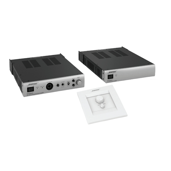
Integrated Zone Amplifier / Zone Amplifier System is a new 1 unit high, 1/2 rack width power amplifier family of products that are used to drive the Bose DS16 and the DS40 speaker systems with individual EQ settings to match. - Page 7 PRODUCT DESCRIPTION Front Panel Inputs and Controls Power Led Blue color LED Power Switch Rocker switch Clip LED Red color LED Mike / Line XLR Combo XLR / Line Combo input jack Combo in level XLR / Line Combo jack. Level control potentiometer Media Player Input 1/8”...
- Page 8 PRODUCT DESCRIPTION Front Panel ® Note: Front Panel controls and indicators are identical on the FreeSpace IZA 190-HZ amplifier. FreeSpace IZA-190 and IZA 250-LZ Setup and Operation Rear Panel FreeSpace IZA 190-HZ FreeSpace IZA 250-LZ...
- Page 9 PRODUCT DESCRIPTION Loudspeaker Connections Use 18 AWg (0.8 mm ) to 14 AWg (2.0 mm ) size wire only. Making loudspeaker connections (IZA 190-HZ) Note: Loudspeaker connections are the same for the ZA 190-HZ amplifier. Wire the 3-pin Euroblock: Use pins 1 (70V) and 3 (COM) for 70V operation. Use pins 2 (100V) and 3 (COM) for 100V operation Making loudspeaker connections (IZA 250-LZ) Note: Loudspeaker connections are the same for the ZA 250-LZ amplifier.
- Page 10 PRODUCT DESCRIPTION 2. Make a single loudspeaker connection or connect two loudspeakers in parallel. When con- necting the loudspeakers in parallel: • Connect the wires from the amplifier to the matching positive (+) and negative (–) terminals on the first loudspeaker. •...
- Page 11 PRODUCT DESCRIPTION Page Input Connections The PAGE INPUT is a mic/line input with a trigger contact closure. This input signal is routed to all outputs (including AUX OUT) when the trigger is detected. This is designed for push-to-talk paging microphones and telephone paging systems. See the diagrams below for input wiring configurations.
- Page 12 Remote Control Connections Remote Volume Control The amplifier is designed to work with the Bose Volume Control User Interface (PC 041966) and Volume Control with A/B Select User Interface (PC 041967) accessories. The REMOTE connec- tor on the rear panel of the amplifier is labeled to match the connectors on the user interfaces.
- Page 13 The amplifier is designed to mute all outputs (including AUX OUT) when a trigger is detected via the MUTE connector. This is triggered from a standard contact closure. Use the included 2-pin Euroblock. Setup – Rear Panel Controls FreeSpace IZA 190-HZ FreeSpace IZA 250-LZ Amplifier mode DIP switches Page/Mic Normal – Bypass Master Determines if page input source will follow the master level output or can be set at an indepen- dent output level to ensure announcements are heard.
- Page 14 Loudspeaker EQ Preset Switch ® Provides loudspeaker equalization presets designed to optimize the performance of Bose FreeSpace DS 16 or DS 40 loudspeakers. A high-pass filter (HPF) setting is also available for use with any passive loudspeakers. the high-pass filter is set at 60 Hz for the IZA 190-HZ and at 40 Hz for the IZA 250-LZ.
- Page 15 Volume Control with A/B Select User Interface accessory. Note: When the Bose Volume Control with A/B Select User Interface is connected, the source select on the front panel of the amplifier will not function. The position of the A/B switch on the user interface will determine what source is selected.
- Page 16 The Bose FreeSpace ZA 190-HZ/250-LZ Zone Amplifier makes system expansion easy. When a system design requires more loudspeakers than the FreeSpace IZA 190-HZ/250-LZ Integrated Zone Amplifier can support, the FreeSpace ZA 190-HZ/250-LZ Zone Amplifier is available to provide additional power.
-
Page 17: Electrostatic Discharge Sensitive (Esds) Device Handling
ELECTROSTATIC DISCHARGE SENSITIVE (ESDS) DEVICE HANDLING This unit contains ESDS devices. We recommend the following precautions when repairing, replacing or transporting ESDS devices: • Perform work at an electrically grounded work station. • Wear wrist straps that connect to the station or heel straps that connect to conductive floor mats. -
Page 18: Packaging Part List, Freespace Iza / Za System (Refer To Figure 1)
PACKAGING PART LIST FreeSpace ® IZA / ZA System (refer to Figure 1) © Item Description Bose Vendor P/N Qty. Note Num ber CONNECTOR KIT 348624-001S SVC- (INCLUDES ITEMS A - H BELOW ) LOMIC04+CONK ZIP BAG 1497-5152+0 FEMALE PLUG, 4P, GREEN... -
Page 19: Main Part List, Freespace Fs Iza 190-Hz Amplifier (Refer To Figure 2)
MAIN PART LIST FreeSpace ® FS IZA 190-HZ Amplifier (refer to Figure 2) ® Item Description Bose Part Vendor Part Number Qty. Note Number Number SCREW, MACHINE, FLAT-CS 2901-3005+3000 CHASSIS 1407-5006+0 TUBE SCREW M3X6 2904-3006+3000 AC INLET 2113-3135+0 BRACKET, REAR... - Page 20 ® Figure 2. FreeSpace IZA 190-HZ Amplifier Exploded View...
-
Page 21: Main Part List, Freespace Za 190-Hz Amplifier (Refer To Figure 3)
MAIN PART LIST FreeSpace ® ZA 190-HZ Amplifier (refer to Figure 3) ® Item Description Bose Part Vendor Part Number Qty. Note Number Number CHASSIS 1407-5017+0 TUBE SCREW M3X6 2904-3006+3000 AC INLET 2113-3135+0 BRACKET, REAR 348589-0310 SVC-HIMIC04+BKT SCREW, MACHINE, FLAT-CS... - Page 22 Figure 3. FreeSpace ® ZA 190-HZ Amplifier Exploded View...
-
Page 23: Main Part List, Freespace Iza 250-Lz Amplifier (Refer To Figure 4)
MAIN PART LIST FreeSpace ® IZA 250-LZ Amplifier (refer to Figure 4) ® Item Description Bose Part Vendor Part Number Qty. Note Number Number CHASSIS 1407-5028+0 TUBE SCREW M3X6 2904-3006+3000 TERMINAL SCREW, M3X8 2904-3008+3000 AC INLET 2113-3135+0 BRACKET, REAR 348589-0010... - Page 24 Figure 4. FreeSpace ® IZA 250-LZ Amplifier Exploded View...
-
Page 25: Main Part List, Freespace Za 250-Lz Amplifier (Refer To Figure 5)
MAIN PART LIST FreeSpace ® ZA 250-LZ Amplifier (refer to Figure 5) ® Item Description Bose Part Vendor Part Number Qty. Note Number Number CHASSIS 1407-5039+0 TUBE SCREW M3X6 2904-3006+3000 TERMINAL SCREW, M3X8 2904-3008+3000 AC INLET 2113-3135+0 TERMINAL BLOCK, 2-PIN... - Page 26 ® Figure 5. FreeSpace ZA 250-LZ Amplifier...
-
Page 27: Electrical Part Lists
ELECTRICAL PART LIST FreeSpace ® IZA 190-HZ Main PCB Assembly Resistors Reference Description Vendor Part Note Designator Number R300 33K, RMF, 2W, 5%, AT, METAL, OXIDE 4719-333J+2-X R301 1K, RMG, 1W, 5%, 2512 4728-102J+3 R302 33K, RMF, 2W, 5%, AT, METAL, OXIDE 4719-333J+2-X R303 33K, RMF, 2W, 5%, AT, METAL, OXIDE... - Page 28 ELECTRICAL PART LIST FreeSpace ® IZA 190-HZ Main PCB Assembly Resistors (continued) Reference Description Vendor Part Note Designator Number R350 24R, RMG, 1/4W, 1%, 1206 4725-240A+6 R351 49.9R, RMG, 1/4W, 1%, 1206 4725-49R9+6 R352 10R, RMG, 1/4W, 5%, 1206 4725-100J+6 R353 16R, RMG, 1/4W, 1%, 1206 4725-160A+6...
- Page 29 ELECTRICAL PART LIST FreeSpace ® IZA 190-HZ Main PCB Assembly Capacitors (continued) Reference Description Vendor Part Note Designator Number C311 100UF, CE, 35V, 20%, RLT, 6.3X11, 105C, LOW, 157Q-107M+K- LUTR C312 0.01UF, CC, 50V, 5%, 0603 150F-103J+P-AC C313 0.1uF, CC, 50V, 10%, 0805, 1.2X2.0 150F-104K+J-BD C314 47UF, CE, 25V, 20%, RLT, P5.0, 5X11, LOW, ESR...
- Page 30 ELECTRICAL PART LIST FreeSpace ® IZA 190-HZ Main PCB Assembly Capacitors (continued) Reference Description Vendor Part Note Designator Number C348 0.1uF, CC, 50V, 10%, 0805, 1.2X2.0 150F-104K+J-BD C349 0.1uF, CC, 50V, 10%, 0805, 1.2X2.0 150F-104K+J-BD C350 1000UF, CE, 35V, 20%, RLT, 12.5X25, 105C, LOW, 157Q-108M+K- X&TR C351...
- Page 31 ELECTRICAL PART LIST FreeSpace ® IZA 190-HZ Main PCB Assembly Capacitors (continued) Reference Description Vendor Part Note Designator Number C389 220PF, CC, 50V, 5%, 0603 150F-221J+P-AC C390 0.1UF, CC, 50V, 5%, 0603 150F-104J+P-AC C391 0.1UF, CC, 50V, 5%, 0603 150F-104J+P-AC C392 0.1UF, CC, 50V, 5%, 0603 150F-104J+P-AC...
- Page 32 ELECTRICAL PART LIST FreeSpace ® IZA 190-HZ Main PCB Assembly Inductors Reference Description Vendor Part Note Designator Number D303A FERRITE, BEAD, 26430000101, (FAIR-RITE) 1808-0670+0 D304C FERRITE, BEAD, 26430000101, (FAIR-RITE) 1808-0670+0 L300 FERRITE, BEAD, INDUCTOR, BL01RN1A1F1J 1808-0680+0 L301 10MH, CHOKE-COMMON, MODE, 10MH, MIN, AC, 1806-4037+0000 240V, 2A, AL L302...
- Page 33 INSULATION, MICA, T-400, 8302, 18X12.7M, , 3100-8040+0 T0220 U302F PLASTIC BUSHING, TO-220A 4152-6830+0 U303 IC, AMP, TDA8920BTH, SOT566-3, ONLY, FOR, 3132-2641+1 BOSE U304B HEAT, SINK, FOR, 7805, 2438-17 5400-9130+0 U304C SCREW, 3X8, TAPPING 2950-3008+3000 U304D SCREW, B-TITE, PH, M2.6X, 6, , MM, BZ, CROSS...
- Page 34 ELECTRICAL PART LIST FreeSpace ® IZA 190-HZ Main PCB Assembly Miscellaneous Reference Description Vendor Part Note Designator Number CONNECTOR, 2P, P3.96, STRAIGHT, M 2101-2780+0 FUS1 FUSE, T5A, 250V, 8X8.5, VDE/, PSE/CCC, RLT, 5120-1144+0-L LITTELFUSE HEATSINK, INNER, 56X28X30, AL-EXT 5401-0271+0 HS1A SCREW, M3X6, BINDING, (BLK) 2904-3006+3000 HS1B...
-
Page 35: Freespace Iza 190-Hz Dsp Pcb Assembly
ELECTRICAL PART LIST FreeSpace ® IZA 190-HZ DSP PCB Assembly Resistors Reference Description Vendor Part Note Designator Number 1K, RMG, 1/16W, 1%, 0603/1608 4723-102A+P 33R, RMG, 1/16W, 5%, 0603, HK, RESISTOR/SA 4723-330J+P-R 33R, RMG, 1/16W, 5%, 0603, HK, RESISTOR/SA 4723-330J+P-R 1K, RMG, 1/16W, 1%, 0603/1608 4723-102A+P 1K, RMG, 1/16W, 1%, 0603/1608... - Page 36 ELECTRICAL PART LIST FreeSpace ® IZA 190-HZ DSP PCB Assembly Resistors (continued) Reference Description Vendor Part Note Designator Number 1K, RMG, 1/16W, 1%, 0603/1608 4723-102A+P 13.7K, RMG, 1/10W, 1%, 0603 4720-1372+P 22K, RMG, 1/16W, 1%, 0603, HK, RESISTOR/SA 4723-223A+P-R 33R, RMG, 1/16W, 5%, 0603, HK, RESISTOR/SA 4723-330J+P-R 10K, RMG, 1/16W, 1%, 0603, HK, RESISTOR/SA 4723-103A+P-R...
- Page 37 ELECTRICAL PART LIST FreeSpace ® IZA 190-HZ DSP PCB Assembly Resistors (continued) Reference Description Vendor Part Note Designator Number 47K, RMG, 1/16W, 1%, 0603, HK, RESISTOR/, S 4723-473A+P-R 820R, RMG, 1/16W, 1%, 0603, HK, RESISTOR/SA 4723-821A+P-R 1K, RMG, 1/16W, 1%, 0603/1608 4723-102A+P R110 820R, RMG, 1/16W, 1%, 0603, HK, RESISTOR/SA...
- Page 38 ELECTRICAL PART LIST FreeSpace ® IZA 190-HZ DSP PCB Assembly Capacitors (continued) Reference Description Vendor Part Note Designator Number 10UF, CE, 16V, 20%, SM, 3X5.4, 85C-2000H 157D-106M+3-EJ 1000PF, CC, 50V, 5%, 0603, X7R 150F-102J+P-AC 220PF, CC, 50V, 5%, 0603 150F-221J+P-AC 220PF, CC, 50V, 5%, 0603 150F-221J+P-AC 1000PF, CC, 50V, 5%, 0603, X7R...
- Page 39 ELECTRICAL PART LIST FreeSpace ® IZA 190-HZ DSP PCB Assembly Capacitors (continued) Reference Description Vendor Part Note Designator Number 270PF, CC, 50V, , 10%, 0603, 1x2 150F-271K+P-AC 560PF, CC, 50V, 10%, 0603/1608, 1X2 150F-561K+P-AC 0.1UF, CC, 50V, 5%, 0603 150F-104J+P-AC 0.1UF, CC, 50V, 5%, 0603 150F-104J+P-AC 0.1UF, CC, 50V, 5%, 0603...
- Page 40 ELECTRICAL PART LIST FreeSpace ® IZA 190-HZ DSP PCB Assembly Diodes Reference Description Vendor Part Note Designator Number LED, SMD, 2X1.25X1.1, GN, 0805 3700-7852+G DIODE, BAV99, SOT23, PHILIPS 4840-8970+3 DIODE, FAST, 75V, 0.5A, BAS316, SOD323 480S-3160+3 DOUBLE, DIODE, BAT54S, SOT-23, SCHOTTK 480T-54S0+3 DOUBLE, DIODE, BAT54S, SOT-23, SCHOTTK 480T-54S0+3...
-
Page 41: Freespace Iza 190-Hz Rear Panel I/O Pcb Assembly
ELECTRICAL PART LIST FreeSpace ® IZA 190-HZ Rear Panel I/O PCB Assembly Resistors Reference Description Vendor Part Note Designator Number 0R, RMG, 1/16W, 1%, 0603 4723-000A+P R100 0R, RMG, 1/8W, 1%, 1206 4721-000A+6 R101 0R, RMG, 1/8W, 1%, 1206 4721-000A+6 R171 5.1K, RMG, 1/16W, 5%, 0603/1608 4723-512J+P... - Page 42 ELECTRICAL PART LIST FreeSpace ® IZA 190-HZ Rear Panel I/O PCB Assembly Resistors (continued) Reference Description Vendor Part Note Designator Number R243 10K, RMG, 1/16W, 1%, 0603, HK, RESISTOR/SA 4723-103A+P-R R244 10K, RMG, 1/16W, 1%, 0603, HK, RESISTOR/SA 4723-103A+P-R R245 10K, RMG, 1/16W, 1%, 0603, HK, RESISTOR/SA 4723-103A+P-R R246...
- Page 43 ELECTRICAL PART LIST FreeSpace ® IZA 190-HZ Rear Panel I/O PCB Assembly Capacitors (continued) Reference Description Vendor Part Note Designator Number C216 1000PF, CC, 50V, 5%, 0603, X7R 150F-102J+P-AC C217 1000PF, CC, 50V, 5%, 0603, X7R 150F-102J+P-AC C218 0.1UF, CC, 50V, 5%, 0603 150F-104J+P-AC C219 0.01uF, CC, 50V, 10%, 0603, 1x2...
- Page 44 ELECTRICAL PART LIST FreeSpace ® IZA 190-HZ Rear Panel I/O PCB Assembly Capacitors (continued) Reference Description Vendor Part Note Designator Number C268 0.1UF, CC, 50V, 5%, 0603 150F-104J+P-AC C271 0.1UF, CC, 50V, 5%, 0603 150F-104J+P-AC C272 0.1UF, CC, 50V, 5%, 0603 150F-104J+P-AC C273 0.1UF, CC, 50V, 5%, 0603...
- Page 45 ELECTRICAL PART LIST FreeSpace ® IZA 190-HZ Rear Panel I/O PCB Assembly Transistors Reference Description Vendor Part Note Designator Number Q200 TR, MMBT4403LT1G, SMD 4854-4030+3 Q201 TR, MMBT4403LT1G, SMD 4854-4030+3 Q202 TR, MMBT4403LT1G, SMD 4854-4030+3 Q203 TR, MMBT4403LT1G, SMD 4854-4030+3 Q204 TR, MMBT4403LT1G, SMD 4854-4030+3...
-
Page 46: Freespace Iza 190-Hz 3.5Mm Jack Pcb Assembly
ELECTRICAL PART LIST FreeSpace ® IZA 190-HZ 3.5mm Jack PCB Assembly Resistors Reference Description Vendor Part Note Designator Number 5.1K, RMG, 1/16W, 1%, 0603/1608 4723-512A SUPPRESSOR, 26V, 30A, ESD, TVM1G260M111 480M-1110 1K, RMG, 1/16W, 1%, 0603/1608 4723-102A R103 1M, RMG, 1/16W, 1%, 0603 4723-105A R104 5.1K, RMG, 1/16W, 1%, 0603/1608... - Page 47 ELECTRICAL PART LIST FreeSpace ® IZA 190-HZ 3.5mm Jack PCB Assembly Capacitors (continued) Reference Description Vendor Part Note Designator Number C108 10UF, CE, 16V, 20%, SM, 3X5.4, 85C-2000H 157D-106MEJ C109 10UF, CE, 16V, 20%, SM, 3X5.4, 85C-2000H 157D-106MEJ C111 100PF, CC, 50V, 5%, 0603/1608, 1X2 150F-101JAC C113 100PF, CC, 50V, 5%, 0603/1608, 1X2...
-
Page 48: Freespace Iza 190-Hz Led Pcb Assembly
40TEETH VR102 VR, ROTARY, B20KX1, 20%, C.C, V, L=30, 4751-227E 40TEETH VR103 VR, ROTARY, B20KX1, 20%, V, L=15 4751-2280 FreeSpace IZA 190-HZ LED PCB Assembly Resistors Reference Description Vendor Part Note Designator Number R116 300R, RMG, 1/16W, 5%, 0603... - Page 49 ELECTRICAL PART LIST FreeSpace ® IZA 190-HZ MIC PCB Assembly Resistors Reference Description Vendor Part Note Designator Number R145 0R, RMG, 1/16W, 1%, 0603 4723-000A R155 0R, RMG, 1/16W, 1%, 0603 4723-000JR R125 10R, RMG, 1/16W, 5%, 0603/1608 4723-100J R127 10R, RMG, 1/16W, 5%, 0603/1608 4723-100J R144...
- Page 50 ELECTRICAL PART LIST FreeSpace ® IZA 190-HZ MIC PCB Assembly Capacitors (continued) Reference Description Vendor Part Note Designator Number C123 220UF, CE, 6.3V, 20%, SM, 6.3X5.3, NOVER 157B-227MLJU C125 220UF, CE, 6.3V, 20%, SM, 6.3X5.3, NOVER 157B-227MLJU C127 220UF, CE, 6.3V, 20%, SM, 6.3X5.3, NOVER 157B-227MLJU C115 10UF, CE, 16V, 20%, SM, 3X5.4, 85C-2000H...
-
Page 51: Freespace Iza 190-Hz Output Pcb Assembly
2102-090S J100 JACK, MIC, PHONE, COMBO, 11P, NCJ10FI-H-0, 2113-3213 CON GND WIRE, GROUND, 1P, L=58, GREEN/YRL, RING 7012-9970 FreeSpace IZA 190-HZ Output PCB Assembly Inductors Reference Description Vendor Part Note Designator Number FERRITE, COIL, 1.4M, 28%, BL15.2, RL, P5 1807-142T5 ... -
Page 52: Freespace Za 190-Hz Main Pcb Assembly
ELECTRICAL PART LIST FreeSpace ® ZA 190-HZ Main PCB Assembly Resistors Reference Description Vendor Part Note Designator Number R300 33K, RMF, 2W, 5%, AT, METAL, OXIDE 4719-333J+2-X R301 1K, RMG, 1W, 5%, 2512 4728-102J+3 R302 33K, RMF, 2W, 5%, AT, METAL, OXIDE 4719-333J+2-X R303 33K, RMF, 2W, 5%, AT, METAL, OXIDE... - Page 53 ELECTRICAL PART LIST FreeSpace ® ZA 190-HZ Main PCB Assembly Resistors (continued) Reference Description Vendor Part Note Designator Number R345 402K, RMG, 1/16W, 1%, 0603 4723-4023+P R346 10K, RMG, 1/16W, 1%, 0603, HK, 4723-103A+P-R RESISTOR/SAMSUNG R347 210K, RMG, 1/16W, 1%, 0603 4723-214A+P R348 22R, RMG, 1W, 5%, 2512...
- Page 54 ELECTRICAL PART LIST FreeSpace ® ZA 190-HZ Main PCB Assembly Capacitors Reference Description Vendor Part Note Designator Number C300 3300PF, CC, 1000V, 10%, RLT, 10X4, X7R, 125C 150N-332K+K-SG C301 470UF, CE, 250V, 20%, RL, 30X30, 105C 157R-477M+5-$$T C302 470UF, CE, 250V, 20%, RL, 30X30, 105C 157R-477M+5-$$T C303 3300PF, CC, 1000V, 10%, RLT, 10X4, X7R, 125C...
- Page 55 ELECTRICAL PART LIST FreeSpace ® ZA 190-HZ Main PCB Assembly Capacitors (continued) Reference Description Vendor Part Note Designator Number C340 1000UF, CE, 35V, 20%, RLT, 12.5X25, 105C, LOW 157Q-108M+K- X&TR C341 220PF, CC, 50V, 5%, 0603 150F-221J+P-AC C342 220PF, CC, 50V, 5%, 0603 150F-221J+P-AC C343 220PF, CC, 50V, 5%, 0603...
- Page 56 ELECTRICAL PART LIST FreeSpace ® ZA 190-HZ Main PCB Assembly Capacitors (continued) Reference Description Vendor Part Note Designator Number C380 220PF, CC, 50V, 5%, 0603 150F-221J+P-AC C381 1000PF, CC, 250V, 5%, 0805 150R-102J+J-BD C382 1000UF, CE, 35V, 20%, RLT, 12.5X25, 105C, LOW 157Q-108M+K- X&TR C383...
- Page 57 ELECTRICAL PART LIST FreeSpace ® ZA 190-HZ Main PCB Assembly Capacitors (continued) Reference Description Vendor Part Note Designator Number C488 3300PF, CC, 1000V, 10%, RLT, 10X4, X7R, 125C 150N-332K+K-SG CX300 0.33UF, CM, 300V, 10%, RB, P15, 18X15.5X10 1511-334K+9-03Z CX301 0.33UF, CM, 300V, 10%, RB, P15, 18X15.5X10 1511-334K+9-03Z XYC301 330PF, CC, 250V, 10%, YKP, RL, 8.5X8.5...
- Page 58 ELECTRICAL PART LIST FreeSpace ® ZA 190-HZ Main PCB Assembly Diodes (continued) Reference Description Vendor Part Note Designator Number D308 RECTIFIER, ES1D, 200V, 1.1A, SMD 4840-9190+3 D309 RECTIFIER, UF4006-T, GI, AT 4840-8530+2 D311 RECTIFIER, ES1D, 200V, 1.1A, SMD 4840-9190+3 D312 RECTIFIER, ES1D, 200V, 1.1A, SMD 4840-9190+3 D314...
- Page 59 ELECTRICAL PART LIST FreeSpace ® ZA 190-HZ Main PCB Assembly Miscellaneous Reference Description Vendor Part Note Designator Number FUS1 FUSE, T5A, 250V, 8X8.5, VDE/, PSE/CCC, RLT, 5120-1144+0-L LITTELFUSE HEATSINK, INNER, 56X28X30, AL-EXT 5401-0271+0 HS1A SCREW, M3X6, BINDING, (BLK) 2904-3006+3000 HS1B SCREW, M3X6, BINDING, (BLK) 2904-3006+3000 HEATSINK, (214), 20MM-HIGH, HOLE...
-
Page 60: Freespace Za 190-Hz Rear I/O Panel Pcb Assembly
ELECTRICAL PART LIST FreeSpace ® ZA 190-HZ Rear I/O Panel PCB Assembly Resistors Reference Description Vendor Part Note Designator Number R501 100R, RMG, 1/16W, 1%, 0603 4723-101A+P R502 10K, RMG, 1/16W, 1%, 0603, HK, 4723-103A+P-R RESISTOR/SAMSUNG R503 3.3K, RMG, 1/16W, 1%, 0603, HK, 4723-332A+P-R RESISTOR/SAMSUNG R504... - Page 61 ELECTRICAL PART LIST ® FreeSpace ZA 190-HZ Rear I/O Panel PCB Assembly Resistors (continued) Reference Description Vendor Part Note Designator Number R532 100R, RMG, 1/16W, 1%, 0603 4723-101A+P R558 10K, RMG, 1/16W, 1%, 0603, HK, 4723-103A+P-R RESISTOR/SAMSUNG R559 10K, RMG, 1/16W, 1%, 0603, HK, 4723-103A+P-R RESISTOR/SAMSUNG R560...
- Page 62 ELECTRICAL PART LIST FreeSpace ® ZA 190-HZ Rear I/O Panel PCB Assembly Inductors Reference Description Vendor Part Note Designator Number L501 EMI, FILTER, 120R, 100MHZ, BLM21AG121SN1D, 1803-0087+0 0805, MUR L502 EMI, FILTER, 120R, 100MHZ, BLM21AG121SN1D, 1803-0087+0 0805, MUR Diodes Reference Description Vendor Part...
-
Page 63: Freespace Za 190-Hz Led Pcb Assembly
ELECTRICAL PART LIST FreeSpace ® ZA 190-HZ LED PCB Assembly Resistors Reference Description Vendor Part Note Designator Number R114 0R RMG 1/16W 1% 0603 4723-000A R116 4.7K RMG 1/16W 5% 0603 HK RESISTOR/SAMS 4723-472JR Diodes Reference Description Vendor Part Note Designator Number... -
Page 64: Freespace Iza 250-Lz Main Pcb Assembly
ELECTRICAL PART LIST FreeSpace ® IZA 250-LZ Main PCB Assembly Resistors Reference Description Vendor Part Note Designator Number R300 RMF, 2W, 33K, 5%, AT, METAL, OXIDE 4719-333J+2-X R301 1K, RMG, 1W, 5%, 2512 4728-102J+3 R302 RMF, 2W, 33K, 5%, AT, METAL, OXIDE 4719-333J+2-X R303 RMF, 2W, 33K, 5%, AT, METAL, OXIDE... - Page 65 ELECTRICAL PART LIST FreeSpace ® IZA 250-LZ Main PCB Assembly Resistors (continued) Reference Description Vendor Part Note Designator Number R344 20K, RMG, 1/16W, 1%, 0603/1608 4723-203A+P R345 402K, RMG, 1/16W, 1%, 0603 4723-4023+P R346 10K, RMG, 1/16W, 1%, 0603, HK, 4723-103A+P-R RESISTOR/SAMSUNG R347...
- Page 66 ELECTRICAL PART LIST FreeSpace ® IZA 250-LZ Main PCB Assembly Capacitors Reference Description Vendor Part Note Designator Number C142 1000PF, CC, 250V, 5%, 0805 150R-102J+J-BD C143 1000PF, CC, 250V, 5%, 0805 150R-102J+J-BD C300 3300PF, CC, 1000V, 10%, RLT, 10X4, X7R, 125C 150N-332K+K-SG C301 470UF, CE, 250V, 20%, RL, 30X30, 105C...
- Page 67 ELECTRICAL PART LIST FreeSpace ® IZA 250-LZ Main PCB Assembly Capacitors (continued) Reference Description Vendor Part Note Designator Number C339 470UF, CE, 35V, 20%, RLT, 10X20, 105C, LOW, 157Q-477M+K- S9RT C340 1000UF, CE, 35V, 20%, RLT, 12.5X25, 105C, LOW, 157Q-108M+K- X&TR C341 220PF, CC, 50V, 5%, 0603...
- Page 68 ELECTRICAL PART LIST FreeSpace ® IZA 250-LZ Main PCB Assembly Capacitors (continued) Reference Description Vendor Part Note Designator Number C380 220PF, CC, 50V, 5%, 0603 150F-221J+P-AC C381 1000PF, CC, 250V, 5%, 0805 150R-102J+J-BD C383 0.01UF, CC, 50V, 5%, 0603 150F-103J+P-AC C384 0.1uF, CC, 50V, 10%, 0805, 1.2X2.0 150F-104K+J-BD...
- Page 69 ELECTRICAL PART LIST FreeSpace ® IZA 250-LZ Main PCB Assembly Capacitors (continued) Reference Description Vendor Part Note Designator Number XYC303 330PF, CC, 250V, 10%, YKP, RL, 8.5X8.5 150R-331K+5-PP XYC304 1000PF, CC, 400V, 20%, RL, Y5, , U, 9.5X8, 150T-102M+5-RO AH09E102MLO YC300 1000PF, CC, 400V, 20%, RL, Y5, , U, 9.5X8, 150T-102M+5-RO...
- Page 70 ELECTRICAL PART LIST FreeSpace ® IZA 250-LZ Main PCB Assembly Diodes (continued) Reference Description Vendor Part Note Designator Number D314 RECT, 200V, 2A, ER2D, SMB/DO-214AA, SM 480E-R2D0+3 DZ300 DZ, 5W, 150V, 5%, AT 483B-1519+2 Z300 DZ, 5W, 10V, 5%, 1N5347B, AT, ON 483B-1005+2 Z301 DZ, 5W, 13V, 5%, AT...
- Page 71 ELECTRICAL PART LIST FreeSpace ® IZA 250-LZ Main PCB Assembly Miscellaneous (continued) Reference Description Vendor Part Note Designator Number HS3B SCREW, 3X8, TAPPING 2950-3008+3000 WAFER, 2P, P7.92, STRAIGHT 2101-3092+0 J109A 2P, WAFER, P2.0, ST, 25055440, CT, AMP 2101-1424+0 11P, ST, WAFER, P=2.0 2102-110S+003 SURGE, PROTECTOR, 270V, 4500A, D15, 2706-0003+0...
-
Page 72: Freespace Iza 250-Lz Dsp Pcb Assembly
ELECTRICAL PART LIST FreeSpace ® IZA 250-LZ DSP PCB Assembly Resistors Reference Description Vendor Part Note Designator Number 1K, RMG, 1/16W, 1%, 0603/1608 4723-102A+P 33R, RMG, 1/16W, 5%, 0603, HK, RESISTOR/SA 4723-330J+P-R 33R, RMG, 1/16W, 5%, 0603, HK, RESISTOR/SA 4723-330J+P-R 1K, RMG, 1/16W, 1%, 0603/1608 4723-102A+P 1K, RMG, 1/16W, 1%, 0603/1608... - Page 73 ELECTRICAL PART LIST FreeSpace ® IZA 250-LZ DSP PCB Assembly Resistors (continued) Reference Description Vendor Part Note Designator Number 13.7K, RMG, 1/10W, 1%, 0603 4720-1372+P 22K, RMG, 1/16W, 1%, 0603, HK, RESISTOR/SA 4723-223A+P-R 33R, RMG, 1/16W, 5%, 0603, HK, RESISTOR/SA 4723-330J+P-R 10K, RMG, 1/16W, 1%, 0603, HK, RESISTOR/SA 4723-103A+P-R...
- Page 74 ELECTRICAL PART LIST FreeSpace ® IZA 250-LZ DSP PCB Assembly Resistors (continued) Reference Description Vendor Part Note Designator Number 47K, RMG, 1/16W, 1%, 0603, HK, RESISTOR/S 4723-473A+P-R 820R, RMG, 1/16W, 1%, 0603, HK, RESISTOR/SA 4723-821A+P-R 1K, RMG, 1/16W, 1%, 0603/1608 4723-102A+P R110 820R, RMG, 1/16W, 1%, 0603, HK, RESISTOR/SA...
- Page 75 ELECTRICAL PART LIST FreeSpace ® IZA 250-LZ DSP PCB Assembly Capacitors (continued) Reference Description Vendor Part Note Designator Number 10UF, CE, 16V, 20%, SM, 3X5.4, 85C-2000H 157D-106M+3-EJ 10UF, CE, 16V, 20%, SM, 3X5.4, 85C-2000H 157D-106M+3-EJ 220PF, CC, 50V, 5%, 0603 150F-221J+P-AC 220PF, CC, 50V, 5%, 0603 150F-221J+P-AC...
- Page 76 ELECTRICAL PART LIST FreeSpace ® IZA 250-LZ DSP PCB Assembly Capacitors (continued) Reference Description Vendor Part Note Designator Number 33PF, CC, 50V, 5%, 0603/1608, , 1X2 150F-330J+P-AC 33PF, CC, 50V, 5%, 0603/1608, , 1X2 150F-330J+P-AC 0.1UF, CC, 50V, 5%, 0603 150F-104J+P-AC 0.1UF, CC, 50V, 5%, 0603 150F-104J+P-AC...
- Page 77 ELECTRICAL PART LIST FreeSpace ® IZA 250-LZ DSP PCB Assembly Diodes Reference Description Vendor Part Note Designator Number LED, SMD, 2X1.25X1.1, GN, 0805 3700-7852+G BAV99, SOT23, PHILIPS 4840-8970+3 DIODE, FAST, 75V, 0.5A, BAS316, SOD323 480S-3160+3 DOUBLE, DIODE, BAT54S, SOT-23, SCHOTTKY 480T-54S0+3 DOUBLE, DIODE, BAT54S, SOT-23, SCHOTTKY 480T-54S0+3...
-
Page 78: Freespace Iza 250-Lz Rear Panel I/O Pcb Assembly
ELECTRICAL PART LIST FreeSpace ® IZA 250-LZ Rear Panel I/O PCB Assembly Resistors Reference Description Vendor Part Note Designator Number 0R, RMG, 1/16W, 1%, 0603 4723-000A+P R100 0R, RMG, 1/8W, 1%, 1206 4721-000A+6 R101 0R, RMG, 1/8W, 1%, 1206 4721-000A+6 R171 5.1K, RMG, 1/16W, 5%, 0603/1608 4723-512J+P... - Page 79 ELECTRICAL PART LIST FreeSpace ® IZA 250-LZ Rear Panel I/O PCB Assembly Resistors (continued) Reference Description Vendor Part Note Designator Number R243 10K, RMG, 1/16W, 1%, 0603, HK, RESISTOR/SA 4723-103A+P-R R244 10K, RMG, 1/16W, 1%, 0603, HK, RESISTOR/SA 4723-103A+P-R R245 10K, RMG, 1/16W, 1%, 0603, HK, RESISTOR/SA 4723-103A+P-R R246...
- Page 80 ELECTRICAL PART LIST FreeSpace ® IZA 250-LZ Rear Panel I/O PCB Assembly Capacitors (continued) Reference Description Vendor Part Note Designator Number C216 1000PF, CC, 50V, 5%, 0603, X7R 150F-102J+P-AC C217 1000PF, CC, 50V, 5%, 0603, X7R 150F-102J+P-AC C218 0.1UF, CC, 50V, 5%, 0603 150F-104J+P-AC C219 0.01uF, CC, 50V, 10%, 0603, 1x2...
- Page 81 ELECTRICAL PART LIST FreeSpace ® IZA 250-LZ Rear Panel I/O PCB Assembly Capacitors (continued) Reference Description Vendor Part Note Designator Number C268 0.1UF, CC, 50V, 5%, 0603 150F-104J+P-AC C271 0.1UF, CC, 50V, 5%, 0603 150F-104J+P-AC C272 0.1UF, CC, 50V, 5%, 0603 150F-104J+P-AC C273 0.1UF, CC, 50V, 5%, 0603...
- Page 82 ELECTRICAL PART LIST FreeSpace ® IZA 250-LZ Rear Panel I/O PCB Assembly Transistors Reference Description Vendor Part Note Designator Number Q200 MMBT4403LT1G, SMD 4854-4030+3 Q201 MMBT4403LT1G, SMD 4854-4030+3 Q202 MMBT4403LT1G, SMD 4854-4030+3 Q203 MMBT4403LT1G, SMD 4854-4030+3 Q204 MMBT4403LT1G, SMD 4854-4030+3 Q205 NPN, MMBT4401, SOT-23, HFE:20-300, SM 4854-4010+3...
-
Page 83: Freespace Iza 250-Lz 3.5Mm Jack Pcb Assembly
ELECTRICAL PART LIST FreeSpace ® IZA 250-LZ 3.5mm Jack PCB Assembly Resistors Reference Description Vendor Part Note Designator Number 5.1K, RMG, 1/16W, 1%, 0603/1608 4723-512A SUPPRESSOR, 26V, 30A, ESD, TVM1G260M111 480M-1110 1K, RMG, 1/16W, 1%, 0603/1608 4723-102A R159 24.3K, RMG, 1/10W, 1%, 0603 4720-2432 R161 24.3K, RMG, 1/10W, 1%, 0603... - Page 84 ELECTRICAL PART LIST FreeSpace ® IZA 250-LZ 3.5mm Jack PCB Assembly Capacitors Reference Description Vendor Part Note Designator Number C111 100PF, CC, 50V, 5%, 0603/1608, 1X2 150F-101JAC C113 100PF, CC, 50V, 5%, 0603/1608, 1X2 150F-101JAC C129 100PF, CC, 50V, 5%, 0603/1608, 1X2 150F-101JAC C147 100PF, CC, 50V, 5%, 0603/1608, 1X2...
- Page 85 ELECTRICAL PART LIST FreeSpace ® IZA 250-LZ 3.5mm Jack PCB Assembly Diodes Reference Description Vendor Part Note Designator Number BAV99, SOT23, PHILIPS 4840-8970 D102 BAT54S, SOT-23, SCHOTTKY 480T-54S0 D107 BAT54S, SOT-23, SCHOTTKY 480T-54S0 D109 BAT54S, SOT-23, SCHOTTKY 480T-54S0 D105 BAV99, SOT23, PHILIPS 4840-8970 D106 BAV99, SOT23, PHILIPS...
-
Page 86: Freespace Iza 250-Lz Led Pcb Assembly
ELECTRICAL PART LIST FreeSpace ® IZA 250-LZ LED PCB Assembly Resistors Reference Description Vendor Part Note Designator Number R116 300R, RMG, 1/16W, 5%, 0603 4723-301J+P R118 300R, RMG, 1/16W, 5%, 0603 4723-301J+P Diodes Reference Description Vendor Part Note Designator Number D313 SENSOR, LED, 3MM, BLUE, SP, SLR343BB, T,... - Page 87 ELECTRICAL PART LIST FreeSpace ® IZA 250-LZ MIC PCB Assembly Capacitors Reference Description Vendor Part Note Designator Number C115 10UF CE 16V 20% SM 3X5.4 85C-2000H 157D-106MEJ C116 10UF CE 16V 20% SM 3X5.4 85C-2000H 157D-106MEJ C120 0.1uF CC 50V 10% 0603/1608 1x2 150F-104KAC C121 0.1uF CC 50V 10% 0603/1608 1x2...
- Page 88 ELECTRICAL PART LIST FreeSpace ® IZA 250-LZ MIC PCB Assembly Transistors Reference Description Vendor Part Note Designator Number Q100 NPN MMBT4401 SOT-23 HFE: 20-300 SM 4854-4010 Q101 NPN MMBT4401 SOT-23 HFE: 20-300 SM 4854-4010 Q102 MMBT4403LT1G SMD 4854-4030 Q103 MMBT4403LT1G SMD 4854-4030 Q104 MMBT4403LT1G SMD...
-
Page 89: Freespace Za 250-Lz Main Pcb Assembly
ELECTRICAL PART LIST FreeSpace ® ZA 250-LZ Main PCB Assembly Resistors Reference Description Vendor Part Note Designator Number R300 33K, RMF, 2W, 5%, AT, METAL, OXIDE 4719-333J+2-X R301 1K, RMG, 1W, 5%, 2512 4728-102J+3 R302 33K, RMF, 2W, 5%, AT, METAL, OXIDE 4719-333J+2-X R303 33K, RMF, 2W, 5%, AT, METAL, OXIDE... - Page 90 ELECTRICAL PART LIST FreeSpace ® ZA 250-LZ Main PCB Assembly Resistors (continued) Reference Description Vendor Part Note Designator Number R344 20K, RMG, 1/16W, 1%, 0603/1608 4723-203A+P R345 402K, RMG, 1/16W, 1%, 0603 4723-4023+P R346 10K, RMG, 1/16W, 1%, 0603, HK, 4723-103A+P-R RESISTOR/SAMSUNG R347...
- Page 91 ELECTRICAL PART LIST FreeSpace ® ZA 250-LZ Main PCB Assembly Capacitors Reference Description Vendor Part Note Designator Number C142 1000PF, CC, 250V, 5%, 0805 150R-102J+J-BD C143 1000PF, CC, 250V, 5%, 0805 150R-102J+J-BD C300 3300PF, CC, 1000V, 10%, RLT, 10X4, X7R, 125C 150N-332K+K-SG C301 470UF, CE, 250V, 20%, RL, 30X30, 105C...
- Page 92 ELECTRICAL PART LIST FreeSpace ® ZA 250-LZ Main PCB Assembly Capacitors (continued) Reference Description Vendor Part Note Designator Number C339 470UF, CE, 35V, 20%, RLT, 10X20, 105C, LOW, 157Q-477M+K- S9RT C340 1000UF, CE, 35V, 20%, RLT, 12.5X25, 105C, LOW, 157Q-108M+K- X&TR C341 220PF, CC, 50V, 5%, 0603...
- Page 93 ELECTRICAL PART LIST FreeSpace ® ZA 250-LZ Main PCB Assembly Capacitors (continued) Reference Description Vendor Part Note Designator Number C380 220PF, CC, 50V, 5%, 0603 150F-221J+P-AC C381 1000PF, CC, 250V, 5%, 0805 150R-102J+J-BD C383 0.01UF, CC, 50V, 5%, 0603 150F-103J+P-AC C384 0.1uF, CC, 50V, 10%, 0805, 1.2X2.0 150F-104K+J-BD...
- Page 94 ELECTRICAL PART LIST FreeSpace ® ZA 250-LZ Main PCB Assembly Capacitors (continued) Reference Description Vendor Part Note Designator Number CX301 0.33UF, CM, 300V, 10%, RB, P15, 18X15.5X10 1511-334K+9-03Z XYC301 330PF, CC, 250V, 10%, YKP, RL, 8.5X8.5 150R-331K+5-PP XYC303 330PF, CC, 250V, 10%, YKP, RL, 8.5X8.5 150R-331K+5-PP XYC304 1000PF, CC, 400V, 20%, RL, Y5, U, 9.5X8,...
- Page 95 ELECTRICAL PART LIST FreeSpace ® ZA 250-LZ Main PCB Assembly Diodes (continued) Reference Description Vendor Part Note Designator Number D306 LL4148, SM 4804-1480+3 D307 RECTIFIER, ES1D, 200V, 1.1A, SMD 4840-9190+3 D308 RECTIFIER, ES1D, 200V, 1.1A, SMD 4840-9190+3 D309 RECTIFIER, UF4006-T, GI, AT 4840-8530+2 D311 RECTIFIER, ES1D, 200V, 1.1A, SMD...
- Page 96 ELECTRICAL PART LIST FreeSpace ® ZA 250-LZ Main PCB Assembly Miscellaneous Reference Description Vendor Part Note Designator Number CONNECTOR, 2P, P3.96, STRAIGHT, M 2101-2780+0 CONNECTOR, 2P, P3.96, STRAIGHT, M 2101-2780+0 FUS1 FUSE, T5A, 250V, 8X8.5, VDE/, PSE/CCC, RLT, 5120-1144+0-L LITTELFUSE HEATSINK, INNER, 56X28X30, AL-EXT 5401-0271+0 HS1A...
-
Page 97: Disassembly Procedures
DISASSEMBLY PROCEDURES Note: Refer to Figures 2 through 5 for the 5. Output PCB Assembly Removal following procedures (Hi-Z units only) 1. Top Cover Removal 5.1 Perform procedure 1. 1.1 Remove the eight screws that secure the 5.2 Disconnect the output PCB wiring har- top cover to the chassis. - Page 98 DISASSEMBLY PROCEDURES 8. Mic PCB Assembly Removal (Master units only) 8.1 Perform procedure 1. 8.2 On the front panel, pull off the VR knob, and remove the nut and the plain washer. 8.3 Inside the chassis, make a note of the wiring configuration, and unplug the two wires that go to the front panel power switch.
-
Page 99: Test Procedures
TEST PROCEDURES IZA 250-LZ Amplifier (Low-Z Master Unit) 1.4 On the front panel, apply a 1kHz, -5dBv +/- 2dBv sine wave to the + and - inputs of Items required: the Aux Input jack. Verify a 50W output level Audio Precision ATS-1 or similar on outputs 1 and 2. - Page 100 TEST PROCEDURES 3. Frequency Response Test 3.4 On the front panel, apply a 1kHz, -5dBv +/- 2dBv sine wave to the + and - inputs of 3.1 On the rear panel, apply a 1kHz, -20dBv the Aux Input jack. Adjust the input signal +/- 2dBv sine wave to the Input A and Input B level to obtain a 1W output level on outputs 1 RCA input jacks.
- Page 101 TEST PROCEDURES 4.4 On the front panel, apply a 1kHz, -5dBv 6. Input Signal Clip Level Test +/- 2dBv sine wave to the + and - inputs of the Aux Input jack. Verify a 50W output level 6.1 On the rear panel, apply a 1kHz, -20dBv on outputs 1 and 2.
- Page 102 TEST PROCEDURES 7. Channel Separation Test 8.3 With the output level specified in step 8.2 above, measure the THD level at the Aux Note: A 20kHz filter and A-weighting must be Out RCA jacks. It should be <0.1%. 0.02% used for this test. is ideal.
- Page 103 TEST PROCEDURES 10.3 Apply an audio input to the Page input - Set the Page/Mic Normal - Bypass Master on the rear panel. Verify that when audio is switch to the Bypass Master position. Verify applied to the Page input that it takes priority that inputs 3 (PAGE) and 4 (MIC) are not over all inputs and ducks the sources.
-
Page 104: Iza 190-Hz Amplifier (Hi-Z Master Unit)
TEST PROCEDURES IZA 190-HZ Amplifier (Hi-Z Master Unit) 1.3 On the front panel, apply a 1kHz, -58dBv +/- 3dBv sine wave to the + and - inputs of Items required: the Mic/Line Input jack. Verify a 90W output Audio Precision ATS-1 or similar level on the output connector. - Page 105 TEST PROCEDURES 3. Frequency Response Test 3.4 On the front panel, apply a 1kHz, -5dBv +/- 2dBv sine wave to the + and - inputs of 3.1 On the rear panel, apply a 1kHz, -20dBv the Aux Input jack. Adjust the input signal +/- 2dBv sine wave to the Input A and Input B level to obtain a 1W output level on outputs 1 RCA input jacks.
- Page 106 TEST PROCEDURES 5. Tone Control Frequency Response Test 6.2 On the rear panel, apply a 1kHz, -45dBv +/- 3dBv sine wave to the + and - inputs of 5.1 Set the treble and bass tone controls to the Page Input jack. Observe the Input Clip center.
- Page 107 TEST PROCEDURES 8. Aux Output Frequency Response and 9.4 On the front panel, set the Mic/Line input Noise Test gain control to 12 o’clock. On the rear panel, set the Front Line Mix / Front Mic Duck DIP 8.1 On the front panel, set the master level switch to the Front Mic Duck position.
-
Page 108: Za 250-Lz Amplifier (Low-Z Slave Unit)
TEST PROCEDURES 12.2 OUTPUT MONO or OUTPUT STEREO ZA 250-LZ Amplifier (Low-Z Slave Unit) - Place the Output Mono or Output Stereo DIP switch on the rear panel to the Output Items required: Stereo position. Apply a line level audio signal Audio Precision ATS-1 or similar to Inputs A and B on the rear panel. -
Page 109: Za 190-Hz Amplifier (Hi-Z Slave Unit)
TEST PROCEDURES - Change the input signal frequency to 60Hz. ZA 190-HZ Amplifier (Hi-Z Slave Unit) Verify that the output level is now -1dBr +/- 1dBr. Items required: Audio Precision ATS-1 or similar - Change the input signal frequency to Audio Precision AUX-0025 filter 18kHz. - Page 110 TEST PROCEDURES 4. Signal to Noise Ratio Test Hi-Pot Tester Settings: Note: A 20kHz filter and A-weighting must be HiPot: 1500VAC, rise time = 1 sec., dwell = 3 used for this test. seconds, current limit = 5mA 4.1 On the rear panel, apply a 1kHz, 0dBv 1.1 Connect the AC mains cord to the back +/- 1dBv sine wave to the RCA input jacks.
-
Page 111: Service Manual Revision History
SERVICE MANUAL REVISION HISTORY Date Revision Description of Change Change Driven Pages Level Affected 1/12 Document released at revision 00. Service manual release 2/12 Added new test procedures. New test 99-110 specification 2/13 Packaging part number changes New part numbers 11/2022 Changed HIPOT from .5ma to 5ma Safety Engineering... - Page 112 SPECIFICATIONS AND FEATURES SUBJECT TO CHANGE WITHOUT NOTICE Bose Corporation The Mountain Framingham Massachusetts USA 01701 P/N: 344871-SM Rev. 03 2/2022 (P) http://serviceops.bose.com...
Need help?
Do you have a question about the FreeSpace IZA 190-HZ and is the answer not in the manual?
Questions and answers