Table of Contents
Advertisement
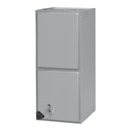
INSTALLATION INSTRUCTIONS
FEATURING INDUSTRY STANDARD R-410A REFRIGERANT:
(-)H1P Standard Efficiency with Aluminum Coil
(-)H2T High Efficiency with Aluminum Coil (2-Stage Non-Communicating)
!
WARNING
These instructions are intended as an aid to qualified licensed
service personnel for proper installation, adjustment and
operation of this unit. Read these instructions thoroughly before
attempting installation or operation. Failure to follow these
instructions may result in improper installation, adjustment,
service or maintenance possibly resulting in fire, electrical
shock, property damage, personal injury or death.
AIR HANDLERS
92-20521-127-05
Advertisement
Table of Contents

Summary of Contents for Ruud Endeavor H1P Series
- Page 1 INSTALLATION INSTRUCTIONS AIR HANDLERS FEATURING INDUSTRY STANDARD R-410A REFRIGERANT: (-)H1P Standard Efficiency with Aluminum Coil (-)H2T High Efficiency with Aluminum Coil (2-Stage Non-Communicating) WARNING These instructions are intended as an aid to qualified licensed service personnel for proper installation, adjustment and operation of this unit.
-
Page 2: Table Of Contents
TABLE OF CONTENTS 1.0 SAFETY INFORMATION ....................... 4 2.0 GENERAL INFORMATION ....................6 2.1 IMPORTANT INFORMATION ABOUT EFFICIENCY & INDOOR AIR QUALITY ....... 6 2.2 CHECKING PRODUCT RECEIVED ....................7 2.3 MODEL NUMBER NOMENCLATURE ....................7 2.4 AVAILABLE MODELS ......................... 8 2.5 Dimensions &... - Page 3 TABLE OF CONTENTS (continued) 3.13.3.3 115/208/240V AIRFLOW PERFORMANCE DATA: (CONSTANT TORQUE MOTOR) ......38 4.0 START-UP ........................... 42 4.1 PRE-START CHECKLIST ......................... 42 4.2 SYSTEM START-UP AND OPERATIONAL CHECK-OUT ............... 42 4.3 SEQUENCE OF OPERATION ......................42 4.3.1 COOLING MODE ............................42 4.3.2 ELECTRIC HEAT MODE ..........................
-
Page 4: Safety Information
1.0 SAFETY INFORMATION WARNING (SEE SECTION 3.13: ELECTRICAL WIRING) Disconnect all power to unit WARNING before installing or servicing. More than one disconnect switch Duct leaks can create an unbalanced system and draw pollutants such as may be required to de-energize dirt, dust, fumes and odors into the home causing property damage. - Page 5 WARNING WARNING (SEE SECTION 3.7: AIR FILTER) PROPOSITION 65: This appli- Do not operate the system without filters. A portion of the dust entrained in ance contains fiberglass insulation. the air may temporarily lodge in the duct runs and at the supply registers. Any Respirable particles of fiberglass circulated dust particles could be heated and charred by contact with the heat- are known to the State of California...
-
Page 6: General Information
NOTICE Use of this air-handler during construction is not recommended. If oper- ation during construction is absolutely required, the following temporary installation requirements must be followed: Installation must comply with all Installation Instructions in this manual including the following items: •... -
Page 7: Checking Product Received
it is important to have the proper balance between the air being supplied to each room and the air returning to the cooling and heating equipment. Proper balance and sealing of the duct system improves the efficiency of the heating and air conditioning system and improves the indoor air quality of the home by reducing the amount of airborne pollutants that enter homes from spaces where the ductwork and/or equipment is located. -
Page 8: Available Models
2.4 AVAILABLE MODELS AVAILABLE 115V MODELS (-)H1PZ1817STANNA (-)H2TZ4821STANNA (-)H2TZ2417STANNA (-)H1PZ4821STANNA (-)H1PZ2417STANNA (-)H2TZ4824STANNA (-)H1PZ3017STANNA (-)H2TZ6024STANNA (-)H2TZ3617STANNA (-)H2TZ3621MTANAA (-)H1PZ3617STANNA (-)H2TZ3621MTANNA (-)H2TZ3621STANNA (-)H2TZ4821STANAA (-)H1PZ3621STANNA (-)H2TZ6021STANAA (-)H1PZ4221STANNA AVAILABLE 208/240V MODELS (-)H1PZ1817STANNJ (-)H1PZ4824STANNJ (-)H2TZ2417STANNJ (-)H2TZ6024STANNJ (-)H1PZ2417STANNJ (-)H1PZ6024STANNJ (-)H1PZ3017STANNJ (-)H2TZ3621MTANAJ (-)H2TZ3617STANNJ (-)H2TZ3621MTANNJ (-)H1PZ3617STANNJ (-)H2TZ4821STANAJ (-)H2TZ3621STANNJ (-)H2TZ6021STANAJ (-)H1PZ3621STANNJ (-)H1PZ4221STANNJ (-)H2TZ4821STANNJ... -
Page 9: Dimensions & Weight
2.5 Dimensions & Weight 2.5.1 DIMENSIONS & WEIGHTS: (-)H1P MODELS FIGURE 3A NOTE: 24” CLEARANCE REQUIRED IN FRONT OF UNIT FOR FILTER DIMENSIONS AND WEIGHTS AND COIL MAINTENANCE. SUPPLY AIR ELECTRICAL CONNECTIONS MAY EXIT TOP OR EITHER SIDE HIGH VOLTAGE CONNECTION 7/8”, 1 3/32”, 1 31/32”... -
Page 10: Dimensions & Weights: (-)H2T Models
2.5.2 DIMENSIONS & WEIGHTS: (-)H2T MODELS FIGURE 3B NOTE: 24” CLEARANCE REQUIRED SUPPLY AIR DIMENSIONS AND WEIGHTS IN FRONT OF UNIT FOR FILTER AND COIL MAINTENANCE. HIGH VOLTAGE CONNECTION 7/8”, 1 3/32”, 1 31/32” DIA. KNOCK OUTS. FLANGES ARE PROVIDED ELECTRICAL CONNECTIONS MAY FOR FIELD INSTALLATION EXIT TOP OR EITHER SIDE... -
Page 11: Importance Of Proper Indoor/Outdoor Match-Ups
2.6 IMPORTANCE OF PROPER INDOOR/ OUTDOOR MATCH-UPS To assure many years of reliable operation and optimum customer comfort and to assure the outdoor unit warranty remains valid, an air-handler model should be selected that is properly matched to the outdoor unit. This is especially critical for heat pump systems to assure proper refrigerant charge balance between the cooling and heating modes. -
Page 12: Quick-Reference Guide For R-410A
Physical Properties: R-410A has an atmospheric boiling point of -62.9°F [-52.7°C] and its saturation pressure at 77°F [25°C] is 224.5 psig. Composition: R-410A is a near-azeotropic mixture of 50% by weight difluoromethane (HFC-32) and 50% by weight pentafluoroethane (HFC-125). Pressure: The pressure of R-410A is approximately 60% (1.6 times) greater than R-22. - Page 13 FIGURE 4 DIMENSIONS FOR REFRIGERANT-TUBING & DRAIN CONNECTIONS VERTICAL AUXILIARY DRAIN CONNECTION HORIZONTAL AUXILIARY DRAIN CONNECTION GAS PIPE LIQUID PIPE MAIN DRAIN PIPE support rails installed at the factory should be left in place to help retain the cabinet insulation. They will be located on the warmer return side of the air-handler for down and horizontal right discharge applications and will therefore not pose a risk for cabinet sweating.
-
Page 14: Installation In An Unconditioned Space
IMPORTANT: To comply with certification agencies and the National Electric Code for down discharge applications, the circuit breaker(s) on field-installed electric heater kits must be re-installed per procedure below so that the breaker switch “on” position and marking is up and the “off” position and marking is down. 1. -
Page 15: Installation In Mobile/Manufactured Homes
FIGURE 6 VERTICAL DOWNFLOW & HORIZONTAL RIGHT APPLICATIONS FACTORY COIL RAIL LOCATION ADDITIONAL COIL RAILS DETAIL A ENSURE THE RETAIN- ING CHANNEL IS FULLY ENGAGED WITH THE ADDITIONAL COIL RAIL. COIL RAILS FACTORY COIL RAIL LOCATION ST-A1213-02-00 FIGURE 7 INDOOR COIL AND DRAIN PAN DETAILS STRAPS HORIZONTAL DRIP PAN TOP AIR STOP... -
Page 16: Installation In Corrosive Environments
screws to air handler and use ⁄ ( lag screws 1 ⁄ ( long to floor. B. If air handler is away from wall attach pipe strap to top of air handler using No. 10 ⁄ ( long self-tapping screws on both sides. Angle strap down and away from back of air handler, remove all slack, and fasten to wall stud of structure using ⁄... -
Page 17: Clearances
FIGURE 9 NOTE: SUSPENDED HORIZONTAL AIR-HANDLER. HORIZONTAL LEFT ORIENTATION DEPICTED IN ILLUSTRATION. HORIZONTAL RIGHT ORIENTATION IS SIMILAR IN INSTALLATION. NOTE: DO NOT BLOCK AIR-HANDLER ACCESS WITH SUPPORT RODS, ALLOW SPACE FOR PROPER SERVICE MAINTENANCE OR REPLACEMENT OF THE COIL AND BLOWER ASSEMBLY. -
Page 18: Ductwork
FIGURE 10 DUCT FLANGE INSTALLATION 3.6 DUCTWORK Field ductwork must comply with the National Fire Protection Association NFPA 90A, NFPA 90B and any applicable local ordinance. WARNING Do not, under any circumstances, connect return ductwork to any other heat producing device such as fireplace insert, stove, etc. Unauthorized use of such devices may result in fire, carbon monoxide poisoning, explo- sion, personal injury or property damage. -
Page 19: Refrigerant Line Connections & Charging
of their useful life, the pressure drop through them increases. Therefore, it is important to factor the “end of life” (dirty) pressure drop of filters into the external static pressure of the duct system when selecting blower speeds and designing ductwork to assure the system is operating at the design CFM and system reliability is not compromised. -
Page 20: Evacuation
3.8.5 EVACUATION If no leaks are detected, evacuate the system down to 500 microns or below before charging the system or opening the service valves on the outdoor unit which will release the charge stored in the outdoor unit into the line set and air-handler coil. Failure to reach 500 microns of vacuum is a sign of a leak or excessive moisture inside the system. -
Page 21: Condensate Drain
FIGURE 13 CONDENSATE DRAIN TRAP ST-A1244-01-00 3.10 CONDENSATE DRAIN Consult local codes or ordinances for specific requirements. IMPORTANT: When making drain fitting connections to the drain pan, use a thin layer of Teflon paste, silicone or Teflon tape and install hand tight. IMPORTANT: When making drain fitting connections to drain pan, do not overtighten. -
Page 22: Electrical Wiring
Movement of air should not be obstructed by furniture, doors, draperies, etc. The thermostat should not be mounted where it will be affected by drafts, hot or cold water pipes or air ducts in walls, radiant heat from fireplace, lamps, the sun, T.V. or an outside wall. -
Page 23: Copper Wire Size - Awg. (3% Voltage Drop)
3.12.4 COPPER WIRE SIZE - AWG. (3% VOLTAGE DROP) 200 [61] 150 [46] 100 [30] 50 [15] SUPPLY CIRCUIT AMPACITY NOTE: WIRE BASED ON COPPER CONDUCTORS 75°C MINIMUM RATING. FOR MORE THAN 3 CONDUCTORS IN A RACEWAY OR CABLE, SEE N.E.C. -
Page 24: Electrical Data - With Electric Heat: (-)H1Pz
3.12.6.1 ELECTRICAL DATA – WITH ELECTRIC HEAT: (-)H1PZ Installation of the UL Listed original equipment manufacturer provided heater kits listed in the following table is recommended for all auxiliary heating requirements. TYPE SUPPLY HEATER CIRCUIT AIR HANDLER HEATER MINIMUM Maximum SINGLE HEATER MOTOR... - Page 25 3.12.6.1 ELECTRICAL DATA – WITH ELECTRIC HEAT: (-)H1PZ - continued TYPE SUPPLY CIRCUIT AIR HANDLER HEATER HEATER MINIMUM MAXIMUM SINGLE HEATER MOTOR MODEL MODEL PH/HZ ELEMENTS CIRCUIT OVERCURRENT CIRCUIT AMPS AMPS (-)H1PZ (208/240V) - KW PER AMPACITY PROTECTION MULTIPLE CIRCUIT RXBH-1724?05J-B 3.6/4.8 1/60...
- Page 26 3.12.6.1 ELECTRICAL DATA – WITH ELECTRIC HEAT: (-)H1PZ - continued TYPE SUPPLY CIRCUIT AIR HANDLER HEATER HEATER MINIMUM MAXIMUM SINGLE HEATER MOTOR MODEL MODEL PH/HZ ELEMENTS CIRCUIT OVERCURRENT CIRCUIT AMPS AMPS (-)H1PZ (208/240V) - KW PER AMPACITY PROTECTION MULTIPLE CIRCUIT RXBH-1724?05J-B 3.6/4.8 1/60...
-
Page 27: Electrical Data - With Electric Heat: (-)H2T
3.12.6.2 ELECTRICAL DATA – WITH ELECTRIC HEAT: (-)H2T Installation of the UL Listed original equipment manufacturer provided heater kits listed in the following table is recommended for all auxiliary heating requirements. AIR HANDLER TYPE SUPPLY CIRCUIT MINIMUM MAXIMUM HEATER MODEL HEATER KW HEATER MOTOR... - Page 28 3.12.6.2 ELECTRICAL DATA – WITH ELECTRIC HEAT: (-)H2T - continued AIR HANDLER TYPE SUPPLY CIRCUIT MINIMUM MAXIMUM HEATER MODEL HEATER KW HEATER MOTOR MODEL PH/HZ ELEMENTS - SINGLE CIRCUIT CIRCUIT OVERCURRENT NUMBER (208/240V) AMPS AMPS (-)H2TZ KW PER MULTIPLE CIRCUIT AMPACITY PROTECTION RXBH-1724?05J-B...
- Page 29 3.12.6.2 ELECTRICAL DATA – WITH ELECTRIC HEAT: (-)H2T - continued AIR HANDLER TYPE SUPPLY CIRCUIT MINIMUM MAXIMUM HEATER MODEL HEATER KW HEATER MOTOR MODEL PH/HZ ELEMENTS - SINGLE CIRCUIT CIRCUIT OVERCURRENT NUMBER (208/240V) AMPS AMPS (-)H2TZ KW PER MULTIPLE CIRCUIT AMPACITY PROTECTION RXBH-1724?05J-B...
-
Page 30: Electric Heater Kit Supplemental Information
3.12.7 ELECTRIC HEATER KIT SUPPLEMENTAL INFORMATION AIR CONDITIONING DIVISION Contractor (-)HLA-HM4821JA should “mark or check” the MARK HEATER INSTALLED/ L’APPAREIL DE CHAUFFAGE DE MARQUE A INSTALLE left column for the kit installed. If a heater kit is list- ed both These are Single the required... -
Page 31: Control Wiring
3.12.8 CONTROL WIRING IMPORTANT: Class 2 low voltage control wire should not be run in conduit with power wiring and must be separated from power wiring, unless class 1 wire of proper voltage rating is used. • Low voltage control wiring should be 18 Awg. color-coded. For lengths longer than 100 ft., 16 Awg. -
Page 32: General Airflow Operating Limits
3.13.1 GENERAL AIRFLOW OPERATING LIMITS *CFM [L/s] per ton requirements are reduced for 5 ton systems. 3.13.2 SELECTING INDOOR BLOWER MOTOR SPEED The (-)H1P and (-)H2T air-handlers must be configured in the field to assure proper air- flow is delivered for the particular application it is being used in. Refer to the AIR-FLOW PERFORMANCE DATA in Section 3.13.3 to determine which speed tap is appropriate for the application. -
Page 33: H2T Models (Constant Torque Ecm Motor) - Single Stage Air-Flow
3.13.2.3 (-)H2T MODELS (CONSTANT TORQUE ECM MOTOR) – SINGLE STAGE AIR-FLOW (-)H2T air-handlers may be matched to single stage outdoor units if properly configured. When using a single speed outdoor unit, Y1 and Y2 thermostat wires must connect to the Y2 (Yellow/Blue) wire on the air handler. For 1/2 tonnage outdoor units (1.5T, 2.5T and 3.5T) the blue wire from the control board should be connected to either T2 or T3 on the motor low voltage terminal block. -
Page 34: 240V Airflow Performance Data: (-)H1P (Psc Motor)
3.13.3.1 240V AIRFLOW PERFORMANCE DATA: (-)H1P (PSC MOTOR) PSC CFM[Us] Air Delivery/RPMNVatts (Dry Coil — No Filter) Manufacturer Blower Size/ Model Motor Speed Recommended Motor Motor Number External Static Pressure-Inches W.C. From Factory Air Flow Range HP [W] Speed (-)H1PZ (Min / Max) CFM # of Speeds 0.1 [.02]... - Page 35 3.13.3.1 240V AIRFLOW PERFORMANCE DATA: (-)H1P (PSC MOTOR) - continued PSC CFM[Us] Air Delivery/RPMNVatts (Dry Coil — No Filter) Manufacturer Blower Size/ Model Motor Speed Recommended Motor Motor External Static Pressure-Inches W.C. Number From Factory Air Flow Range HP [W] Speed (-)H1PZ (Min / Max) CFM...
-
Page 36: 115/208V Airflow Performance Data: (-)H1P (Psc Motor)
3.13.3.2 115/208V AIRFLOW PERFORMANCE DATA: (-)H1P (PSC MOTOR) PSC CFM[Us] Air Delivery/RPM/Watts (Dry Coil — No Filter) Manufacturer Blower Size/ Model Motor Speed Recommended Motor HP Motor External Static Pressure-Inches W.C. Number From Factory Air Flow Range Speed (-)H1PZ (Min / Max) CFM # of Speeds 0.1 [.02] 0.2 [.05]... - Page 37 3.13.3.2 115/208V AIRFLOW PERFORMANCE DATA: (-)H1P (PSC MOTOR) - continued PSC CFM[Us] Air Delivery/RPM/Watts (Dry Coil — No Filter) Manufacturer Blower Size/ Model Motor Speed Recommended Motor HP Motor External Static Pressure-Inches W.C. Number From Factory Air Flow Range Speed (-)H1PZ (Min / Max) CFM # of Speeds...
-
Page 38: 115/208/240V Airflow Performance Data: (Constant Torque Motor)
3.13.3.3 115/208/240V AIRFLOW PERFORMANCE DATA: (CONSTANT TORQUE MOTOR) CFM/RPM/WATTS - Dry Coil-No Filter Motor Blower Size/ Model Tonnage Speed Motor Motor External Static Presure Inches of W.C. No. (-)H2TZ Application From HP [W] Speed Factory # of Speed 10x8 Watts 2417ST 1.5 Ton 1/3 HP [373]... - Page 39 3.13.3.3 115/208/240V AIRFLOW PERFORMANCE DATA: (CONSTANT TORQUE MOTOR) - continued CFM/RPM/WATTS - Dry Coil-No Filter Motor Blower Size/ Model Tonnage Speed Motor Motor External Static Presure Inches of W.C. No. (-)H2TZ Application From HP [W] Speed Factory # of Speed 1000 1021 10x10...
- Page 40 3.13.3.3 115/208/240V AIRFLOW PERFORMANCE DATA: (CONSTANT TORQUE MOTOR) - continued CFM/RPM/WATTS - Dry Coil-No Filter Motor Blower Size/ Model Tonnage Speed Motor Motor External Static Presure Inches of W.C. No. (-)H2TZ Application From HP [W] Speed Factory # of Speed 1106 1032 1042...
- Page 41 3.13.3.3 115/208/240V AIRFLOW PERFORMANCE DATA: (CONSTANT TORQUE MOTOR) - continued CFM/RPM/WATTS - Dry Coil-No Filter Motor Blower Size/ Model Tonnage Speed Motor Motor External Static Presure Inches of W.C. No. (-)H2TZ Application From HP [W] Speed Factory # of Speed 1281 1093 11x11...
-
Page 42: Start-Up
4.0 START-UP PRE-START CHECKLIST ❏ YES Is unit properly located, level, secure and serviceable? ❏ NO Has auxiliary pan been provided under the unit with ❏ YES separate drain? (Units installed above a finished ❏ NO ceiling). ❏ YES Is condensate line properly sized, run, trapped, ❏... -
Page 43: Electric Heat Mode
the call for cooling ends. The air-flow on an (-)H2T air-handler will be reduced to the continuous fan speed while the air-flow on a (-)H1P air-handler will remain constant. 4.3.2 ELECTRIC HEAT MODE When the thermostat calls for the 1st stage of heat, the W1 terminal on the blower con- trol board is energized. -
Page 44: Correcting Electric Heat Kw For Voltage
4.4 CORRECTING ELECTRIC HEAT kW FOR VOLTAGE The actual electric heat kW varies with the supply voltage. Use the following formula to correct the heater rated kW at voltages other than rated voltage. Actual kW = Rated kW x (Actual Voltage / Rated Voltage 4.5 CALCULATING ELECTRIC HEAT CAPACITY IN BTUH... -
Page 45: Checking Refrigerant Charge
Elevation (Feet) Elevation Factor Sea Level 1.08 0.98 1000 0.96 1500 0.95 2000 0.93 2500 0.91 3000 0.90 3500 0.88 4000 0.86 5000 0.83 6000 0.83 7000 0.77 8000 0.74 9000 0.72 10000 0.69 4.7 CHECKING REFRIGERANT CHARGE System refrigerant charging should only be performed after the indoor air-flow is con- firmed to be correct for the application. -
Page 46: Motor Run Capacitor
• If two of the speed tap terminals (T1 – T5) are energized with 24 volts simultaneously, the motor will operate at the higher of the 2 speeds. An example of this is when the G and Y thermostat inputs are both energized in the cooling or heat pump heating mode. -
Page 47: Blower
5.4 BLOWER The blower utilizes a forward curved centrifugal wheel. The blower housing is construct- ed from galvanized sheet metal. The motor is attached with a 4-arm belly band type mount that screws into the side of the blower housing. The control box attaches to the front of the blower housing for assess through the blower access door. -
Page 48: Jumper Bar Kits
or with no disconnect. • Incoming electric power is connected directly to the heater kit power terminals. • The heater kit is provided with 2 power wires that connect to the air-handler power terminal block, providing power to operate the blower motor and controls. •... -
Page 49: Horizontal Adapter Kits
6.6 HORIZONTAL ADAPTER KITS This horizontal adapter kit is used to convert RCH replacement coils for horizontal appli- cations if water management parts from original coil are not usable or are unavailable. See the following table to order proper horizontal adapter kit. Horizontal Adapter Kit Horizontal Adapter Kit RCH Coil Model... -
Page 50: Motor Lubrication
7.4 MOTOR LUBRICATION The blower motor sleeve bearings are pre-lubricated by the motor manufacturer and do not have oiling ports. Motor should operate for an indefinite period of time without addi- tional lubrication. 7.5 BLOWER ASSEMBLY REMOVAL & REPLACEMENT Removing the blower assembly is not normally required for normal service and mainte- nance. -
Page 51: Blower Wheel Replacement
7.7 BLOWER WHEEL REPLACEMENT With the blower assembly removed and the motor assembly removed (see above instructions), remove the screws holding the blower wrap (cutoff) to the blower sides. • With wrap (cutoff) screws removed, cut off end of blower wrap will spring up. Lifting wrap blower wheel is removed through the discharge opening in the blower housing. -
Page 52: Diagnostics
8.0 DIAGNOSTICS Problem Possible Cause (Suggested Fix) Blower Motor will not operate • Failed run capacitor on (-)H1P (replace) • Failed motor (replace) • Failed motor control module on (-)H2T (replace module) • Blown 3A fuse on blower control (check for control circuit short, replace fuse) •... -
Page 53: Wiring Diagrams
9.0 WIRING DIAGRAMS 9.1 WIRING DIAGRAM (-)H1P – 115V... -
Page 54: Wiring Diagram (-)H1P - 208/240V
9.2 WIRING DIAGRAM (-)H1P – 208/240V... -
Page 55: Wiring Diagram (-)H2T - 115V
9.3 WIRING DIAGRAM (-)H2T - 115 V... -
Page 56: Wiring Diagram (-)H2T - 208/240V
9.4 WIRING DIAGRAM (-)H2T – 230V...
Need help?
Do you have a question about the Endeavor H1P Series and is the answer not in the manual?
Questions and answers