Table of Contents
Advertisement
Available languages
Available languages
Quick Links
Advertisement
Table of Contents

Related Manuals for Marco UP3/OIL 12V


Summary of Contents for Marco UP3/OIL 12V
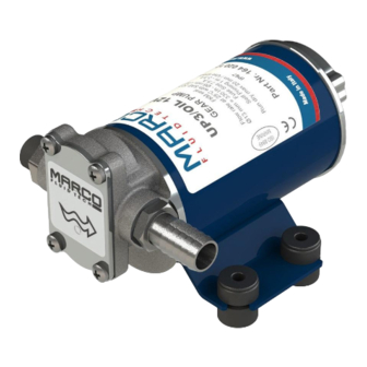
- Page 1 ELETTROPOMPA AUTOADESCANTE PER TRAVASO LIQUIDI SELF-PRIMING ELECTRIC PUMP FOR TRANSFERRING VARIOUS LIQUIDS AVVERTENZE D’USO INSTRUCTIONS FOR USE 164 020 12 - UP3/OIL 12V 164 020 13 - UP3/OIL 24V © S.p.A.
-
Page 2: Descrizione Del Dispositivo
DESCRIZIONE DEL DISPOSITIVO Elettropompa autoadescante progettata per travaso di oli lubrificanti o di liquidi viscosi. Gli elementi pompanti sono costituiti da ingranaggi in bronzo che possono eventualmente girare a secco per brevi periodi. DATI TECNICI Tab.1 IT FUSIBILE PESO CAVI (**) CODICE TIPO VOLT... -
Page 3: Condizioni Ambientali
CONDIZIONI AMBIENTALI ATTENZIONE: le temperature limite indicate si applicano ai componenti del dispositivo e devono essere rispettate per evitare possibili danneggiamenti o malfunzionamenti. CICLO DI LAVORO La pompa può funzionare in servizio continuo alle seguenti condizioni: Ø pressione di esercizio non superiore al 50% della pressione massima dichiarata nei dati tecnici Ø... - Page 4 Per la corretta direzione del flusso del liquido come indicato dalla freccia sulla parte superiore, è necessario collegare il polo positivo (+) della batteria al filo rosso che esce dalla calotta della pompa e il polo negativo (-), al filo nero. I collegamenti elettrici vanno eseguiti utilizzando morsettiere e connessioni adeguate con accurato serraggio dei conduttori.
-
Page 5: Problemi E Soluzioni
PROBLEMI E SOLUZIONI COSA VERIFICARE SE LA POMPA NON PARTE O SI ARRESTA? Ø Verificare l'efficienza del generatore (presenza di tensione) Ø Verificare se il fusibile è interrotto. Ø Verificare la presenza di corpi estranei nel corpo della pompa. Per effettuare ciò è necessario svitare le quattro viti di fissaggio, togliere il piattello di chiusura ed ispezionarne l'interno. -
Page 6: Garanzia
Marco S.p.A. Questi costi saranno limitati ai costi di spedizione tra il magazzino di Marco S.p.A. e la sede del cliente. 7) Nessuna nota di credito o reso sarà emessa prima di un test eseguito dal controllo di qualità... -
Page 7: Product Description
PRODUCT DESCRIPTION Self-priming electric particularly designed for the transfer of lubricating oils or viscous liquids. The pumping elements are made up of bronze gears which can possibly even run dry for brief periods. TECHNICAL DETAILS Tab.1 EN FUSE FLOW RATE (*) WEIGHT WIRE SIZE (**) CODE... -
Page 8: Ambient Conditions
AMBIENT CONDITIONS TEMPERATURE: min.-10°C/14°F - max.60°C/140°F RELATIVE HUMIDITY: max. 90 % WARNING: the above indicated temperature ranges are applicable to all components of the pump and these limits must be respected in order to avoid any possible damage or malfunctioning. OPERATING CYCLE The pump can operate on a continuous cycle with the following conditions: Ø... - Page 9 To ensure the correct directional flow of the fluid as indicated by the arrow on the top plate, it is necessary to connect the positive pole (+) of the battery supply to the red wire on the motor end-cap and the negative pole (-) to the black wire. Electrical connections must be made using adequate terminal blocks and connectors ensuring a tight fitment of the electrical cables.
-
Page 10: Troubleshooting
TROUBLESHOOTING CHECK POINTS IF THE PUMP HAS STOPPED OR WILL NOT START Ø Check the effectiveness of the battery power supply (voltage activity); Ø Check if the fuse has blown; Ø Check for any foreign matter present in the pump body. To do this, disconnect the power supply and unscrew the four fixing screws, remove the front cover plate and inspect the chamber. -
Page 11: Environmental Disposal
5) The Warranty does not cover any related installation costs involved. 6) Transport costs are refundable only in the case where warranty has been duly accepted by Marco Spa and they will be limited to the actual shipment costs between Marco Spa warehouse and the client's delivery address. - Page 12 SCHEDA DI ASSEMBLAGGIO / EXPLODED VIEW Pos. Q.tà Pos. Q.tà Descrizione Descrizione CORPO DADO INGRANAGGIO FOLLE GUARNIZIONE LINGUETTA TIRANTE INGRANAGGIO TRAINANTE INDOTTO O-RING CUSCINETTO PIATTELLO MOLLA DI COMPENSAZIONE VITE CARCASSA RACCORDO O-RING O-RING CALOTTA PORTASPAZZOLE RACCORDO O-RING ANTIVIBRANTE RONDELLA Art. Q.ty Description Art.
- Page 13 INGOMBRI / DIMENSIONS © S.p.A.
- Page 14 DIAGRAMMI / DIAGRAMS DIAGRAMMA PORTATE FLOW RATE DIAGRAM Ø 13 Ø 8 Ø 6 °C DIAGRAMMA ASSORBIMENTI AMPERE-DRAW DIAGRAM °C © S.p.A.
- Page 15 Confermiamo che il prodotto: We confirm that the product: 164 020 12 - UP3/OIL 12V Pompa ad ingranaggi / gear pump 164 020 13 - UP3/OIL 24V Pompa ad ingranaggi / gear pump è conforme alla Direttiva 2014/30/UE (ex. 2004/108/CE) relativa alla compatibilità elettromagnetica.
- Page 16 Questo documento e' proprieta' di Marco S.p.A la riproduzione e l'uso sono vietati. Tutti i diritti sono riservati. Per ulteriori informazioni vedere nostro sito internet - www.marco.it Marco S.p.A Via Mameli 10 - 25014 Castenedolo (Brescia) – Italia tel. +39 030 2134.1 / Fax +39 030 2134.300 Property of MARCO S.p.A reproduction prohibited.
Need help?
Do you have a question about the UP3/OIL 12V and is the answer not in the manual?
Questions and answers