SIGRIST TurBiScat PM 40 Operating Manual
Hide thumbs
Also See for TurBiScat PM 40:
- Brief instructions (29 pages) ,
- Brief instructions (196 pages)
Table of Contents
Advertisement
Quick Links
Advertisement
Table of Contents

Subscribe to Our Youtube Channel
Related Manuals for SIGRIST TurBiScat PM 40


Summary of Contents for SIGRIST TurBiScat PM 40
- Page 1 TurBiScat PM 40 Operating Manual sigrist.com...
- Page 2 © Copyright provisions (Copyright © This document was written by Sigrist-Photometer AG. The copyright is held by Sigrist-Photometer AG. Copying, modifying or translating the contents or passing it on to third parties is only permitted with the agree- ment of Sigrist-Photometer AG.
-
Page 3: Table Of Contents
General view......................... 10 4.1.1 TurBiScat PM 40 with display ...................... 10 4.1.2 TurBiScat PM 40 with SiDis AD 40 .................... 10 Nameplate .......................... 11 Scope of supply and accessory parts................... 11 Mounting ......................... 12 General information on mounting .................. 12 Mounting position of the photometer .................. - Page 4 11.3 Warning messages....................... 51 11.4 Fault messages ........................ 52 11.5 Prio fault messages ...................... 53 12 Specification sheet.................... 54 12.1 TurBiScat PM 40 ........................ 54 12.2 General.......................... 54 12.3 SiDis AD 40 .......................... 55 12.4 Communication modules ...................... 56 4 / 60...
- Page 5 Table of contents 13 Returns........................ 57 14 Decommissioning/ Storage ................... 58 15 Disposal ........................ 59 5 / 60...
-
Page 6: About This Document
NOTE Non-compliance with the instruction manual Sigrist-Photometer AG accepts no liability for damage resulting from failure to observe the instruction manual. Storage of the instruction manual The instruction manual is an integral part of the unit. It must be available to staff at all times. - Page 7 Function read-only The menu function currently described is read-only. «Menu» Menu «Menus» or «functions» included in the software. [Ok] Button Buttons used for navigation in the SIGRIST-Webinterface. Device-specific Placeholder Stands as a placeholder for unspecified, changing term. 7 / 60...
-
Page 8: Your Safety
Your Safety Your Safety Intended use The TurBiScat PM 40 and its peripherals are designed for turbidity measurement in liquids. Possible applications can be found in the following areas: Areas of application Food and beverage industry Applications Filtration monitoring in beverages such as beer, fruit juices, spirits... -
Page 9: Residual Risks
Your Safety Residual risks The device has been built in accordance with the applicable standards and the recognised safety rules and corre- sponds to the state of the art. However, according to the risk assessment of the applied safety standard DIN EN 61010-1, injuries to persons, damage to the device or material damage to the infrastructure cannot be completely ruled out during use. -
Page 10: Device Data
TurBiScat PM 40 WLAN connection WLAN input device Operating device or control system Touchscreen 4.1.2 TurBiScat PM 40 with SiDis AD 40 TurBiScat PM 40 with SiDis AD 40 TurBiScat PM 40 without display SiDis AD 40 WLAN connection WLAN input device... -
Page 11: Nameplate
Device data Nameplate The nameplates are placed on the TurbiScat PM 40 and SiDis AD 40 (2). They contain: Device type Type ext.: Device name PN: Article number SN: Serial number U: Service voltage P: Power DOM: Production date Conformity information... -
Page 12: Mounting
Mounting Mounting General information on mounting Use detailed dimension drawings for photometer and control device mounting. Distance between photometer and stray light sources > 2 m. Avoid the formation of gas bubbles on the sensor head by using a suitable fitting position. Distance between the photometer and pipe bends and cross-section-changing elements >... -
Page 13: Mounting Sidis Ad 40
Mounting Mounting SiDis AD 40 5.4.1 Wall mounting Mount SiDis AD 40 on the wall with two screws according to the dimension drawing. 5.4.2 Rotate mounting plate If necessary, the mounting plate can be rotated by 90° as follows: Loosen four screws (2). Turn the mounting plate in the desired position. -
Page 14: Electrical Installation
Electrical installation Electrical installation DANGER Danger due to improper connection of the operating voltage. Improper connection of the electrical service voltage can be life-threatening. The system can also be damaged in the process. Connection must be carried out by a specialist in accordance with local regulations. Install a disconnecting device near the power supply to disconnect the device from the mains. - Page 15 Electrical installation Digital input 5-28 VDC Function Designation Plug pin no. Colour IN 1 blue IN 2 grey Digital output "High Side Switch" max. 20 mA Function Designation Plug pin no. Colour Out 1 blue Out 2 grey Out 3 pink Out 4 yellow Current output 0/4 ...
-
Page 16: Eg_Poe
Electrical installation 6.2.2 EG_PoE PoE (802.3af, class 0) Cable characteristics: Cat. 6, STP, AWG 24/7, TIA-568A. Fast Ethernet 100Base_T supported Available web services: Web server, Modbus TCP SiDis Female PM Female (A) M12 4-pole socket D Coded Function Plug pin no. 6.2.3 EG_Profibus Female PM... -
Page 17: Eg_Profinet
Electrical installation M12 5-pin socket B Coded Function Plug pin no. PB_A PB_B 6.2.4 EG_Profinet Female PM SiDis A B C A B C Male (A) Female (B) Female (C) M12 8-pole plug A Coded Function Plug pin no. Colour white brown Port 1 /... -
Page 18: Operation
Navigation is done by swiping gestures. Navigation aids are located at the bottom and on the left (2). Without activity, the display switches to the standard display af- ter one minute. SIGRIST-Webinterface Menu settings Status Current measured values 7-day logger diagram... -
Page 19: Commissioning
Commissioning Commissioning Ensure correct mounting and electrical installation. Establish service voltage. w Start screen appears. Rotate display if necessary Rotating the display is only possible in the start-up dis- play. Briefly touch rotation symbol (1). w The display rotates by 90°. Repeat until the display is in the correct position. - Page 20 Access URL with QR code. Alternative: Open browser (e.g. Chrome, Safari). Enter the displayed URL (192.168.10.1). w Login screen appears. Log in to SIGRIST-Webinterface Log in without password. Recommendation: Secure access to the SIGRIST-We- binterface with a password. 20 / 60...
-
Page 21: Settings
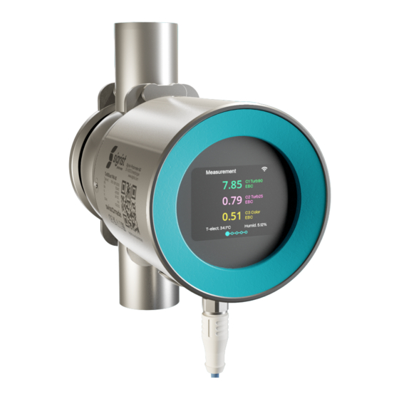
Settings Settings Displays on the photometer Navigation is done by swiping gestures. Navigation aids are located at the bottom and left (2). Without activ- ity, the display switches to the standard display after one minute. Displays on the photometer Sensor status Set standard display see menu Display [} 37]. - Page 22 Settings Start display Symbol for rotating the display [} 19] (only possible during start display) Software version Measurement display WLAN status (Off → grey/ On → light) Other symbols: Logger is saving data/ Pause symbol (unit in service) Channel name with unit Humidity in the sensor Temperature in the sensor Measured value...
- Page 23 Settings WLAN Establish WLAN connection during Commissioning [} 19]. Communication modules (ComModule) IO module: WLAN status (Off → grey/ On → light) Module status: Grey → Inactive/ Blue → Active in idle mode/ Green → Active/ Red → Error. Assigned function: Parametrisable PoE module: WLAN status (Off →...
- Page 24 DHCP: On/ Off Assigned IP address MAC address Station name of the unit Transparent Ethernet: 1: Sigrist web server/ 0: Web server of gateway module Profibus DP module: WLAN status (Off → grey/ On → light) Module status: Grey → Inactive/ Blue → Active in idle mode/ Green →...
- Page 25 Settings Status Meter status WLAN status (Off → grey/ On → light) Error/warning message QR code for error description Limit values Only limit values with an over/under limit are displayed. WLAN status (Off → grey/ On → light) Affected channel Limits: Set limit Act.
- Page 26 Settings System info WLAN status (Off → grey/ On → light) Device type Serial number Designation of the measuring point/device Oper. hours: Operating hours (h) ****** Software version: Main controller Communication controller Sensor controller ****-*** 26 / 60...
-
Page 27: Sigrist-Webinterface
Settings Sigrist-Webinterface 9.2.1 Homepage After logging in, the Sigrist-Webinterface appears in the measuring mode. Open menu Start menu Photometer settings Simple/ [} 28] Extended [} 33] configuration mode Logging on/off Change language Open logger diagram 9.2.2 First steps Open menu (1). Select «language» (2). -
Page 28: Simple Configuration Mode
Orientation of the display. «Access code» Enter access code (numbers only). Used to protect against unauthorised access. «Designation» Enter the name of the measurement point identification in the Sigrist-Webinterface (max. 13 characters). 9.3.1.1 Communication module EG_IO Only available with communication module EG_IO. - Page 29 Settings Parameter Values Default value «0/4mA...20 mA» 0-20 mA/ 4-20 mA 4-20 mA Set current range for measured value output. «For service» 0 value/ Last value Last value Set the measured value output in service mode. «Max. value» 20 ... 21 mA 21 mA Set the highest possible current value at the measured value output.
-
Page 30: Menu: Simulation
Enter DNS server address. Appears if DHCP is set to Off. «Profinet Transparent Mode» On/ Off On: Sigrist web server and Modbus TCP is accessible via Profinet connection. Off: Web server of gateway module (HMS) is accessible. 9.3.1.4 Communication module EG_Profibus Only available with communication module EG_Profibus. -
Page 31: Menu: Recalibration
Settings Parameter Values Default value «Outputs» Off/ All Off/ All On/ 1 ... n On Output specific states at digital outputs. «Light source» Off/ 1, 2 Manually switch the light source on or off for test purposes or fault location (1 = LED turbidity, 2 = LED colour (optional)). - Page 32 «Version Sensor» Software version of the sensor controller. «Version Comm» Software version of the communication controller. «Version Web» Software version of the interface for the Sigrist-Webinterface. «Update firmware» [Check online] [Select file...] [Upload & update] Check online: With an Internet connection, it is possible to check whether new software is available. A valid DNS server address must be available in the communication module.
-
Page 33: Advanced Configuration Mode
Settings Advanced configuration mode If necessary, change the configuration mode. 9.4.1 Menu: IO module EG_IO Only available with communication module EG_IO. IO Configuration\ General Parameter Values Default value «0/4mA...20 mA» 0-20 mA/ 4-20 mA 4-20 mA Set current range for measured value output. «For service»... - Page 34 Settings Parameter Values Default value «Sigi-Link» Off/ On Activate interface parameters for the connection to SICON/ SiDis. «Slave no.» 1 ... 240 Define the slave number with which the photometer is addressed in the control system. «Baud rate» 4800/ 9600/ 19200/ 38400, 57600/ 115200 baud 115200/ 230400 baud Set the baud rate of the Modbus interface (baud rate in bits/s).
-
Page 35: Menu: Wlan
Settings Parameter Values Default value «Measuring range» 0 ... 4000 0 ... 1000 From ... To values of the measuring range. Digital output\ limit value (IO 1 ... 4) This function only appears if the limit value has been activated in the "Digital output" function. Parameter Values Default value... -
Page 36: Menu Configuration
Settings Parameter Values Default value «SSID» XXXXXX Device-specific Displays the SSID of the WLAN base station. «Deactivate after» 300 s If there is no active connection, the WLAN access point is deactivated after the set time. «Password» XXXXXX Enter the password for the WLAN access point. WLAN\ WLAN connection Parameter Values... -
Page 37: Menu: Display
Settings 9.4.7 Menu: Display Display\ General Parameter Values Default value «Values» Min. value/ Max. value/ Mean value Mean value Selection of the measuring value display in the graphic display. «For service» 0 value/ Last value Last value Value displayed in the graphic display during service operation. «Image rotation»... -
Page 38: Menu: Simulation
Settings 9.4.8 Menu: Simulation See Simple Configuration Mode\ Simulation [} 30] 9.4.9 Menu: Recalibration See Simple configuration mode\ Recalibration [} 31] 9.4.10 Menu: Sensor check Parameter Values Default value «Sensor check» start... The sensor check is an internal plausibility check of the photometer. «Check interv.»... -
Page 39: Menu: System
During an online firmware update, operating hours, temperatures, voltages, intensities of the light sources and the error history are transmitted. «Contact information» Sigrist-Photometer AG Enter line 1 of the contact information (max. 47 characters). «Contact information» Switzerland Enter line 2 of the contact information (max. 47 characters). -
Page 40: Menu: Math. Channels
Settings Parameter Values Default value «Offset» -5000 ... 999999 0,000 Offset value is added to the measured value. «Scaling» EBC: 1.000, NTU: 4.000/ 1,000 FTU: 4,000 Set the scaling factor for a customer-specific unit of measurement or for adaptation to laboratory values. The scaling factor is multiplied by the measured value. -
Page 41: Menu: Measuring Info
Settings Parameter Values Default value «Integration» 0 ... 60000 s 10 s Set the integration time for the forming of measured values. The integration is done via a low-pass filter. The set integration time corresponds to the step response of the measured value from 0 ... -
Page 42: Field Bus
Settings Graphical display of measuring values Display over a certain period of time ((X): Time axis/ (Y:) measuring range). The curve colour corresponds to the corresponding measuring channel (7). Time scales Define the time period from which the logger data is to be loaded (preview of data points under position (8)) Large displayed range corresponds to selected range under position (8). - Page 43 Settings 9.6.3.2 Modbus TCP general The EG_POE module or the EG_Profinet module with active transparent mode must be integrated. Alterna- tively, the Modbus TCP interface is available on the WLAN interfaces. The communication runs on port 502. Only one Modbus TCP connection may exist at the same time. An unused connection is terminated after 30 seconds.
- Page 44 Settings Register Address Data type Function Values 30017 0x0010 Real 32-bit Intel single precision bits Measured value 15-0 channel 8 30018 0x0011 Real 32-bit Intel single precision bits 31-16 30019 0x0012 Real 32-bit Intel single precision bits Math channel 1 15-0 30020 0x0013...
-
Page 45: Servicing
CAUTION Unit damage due to lack of maintenance Lack of or inadequate maintenance as well as the use of non-original Sigrist spare parts may damage the device and lead to measurement errors. Always carry out servicing work according to the servicing schedule. -
Page 46: Clean Sensor Head
Unprotected skin or eye contact with formazine may cause skin or eye damage. Wear protective goggles and gloves. Wash hands after work. 10.4.1 Overview of control unit TurBiScat PM 40 Clamp ring ® Adapter VARINLINE Level indicator Filling funnel holder... -
Page 47: Cleaning The Control Unit
Servicing 10.4.2 Cleaning the control unit NOTE Cleaning the control unit Unsuitable cleaning agents can cause damage to the solid body. Clean the control unit with a soft, lint-free cloth, inside and out. In case of heavy soiling, a mild, abrasive-free cleaning agent can be used (e.g. - Page 48 Servicing Put on control unit Align pin with recess (2). Put on the control unit. ® Fastening the control unit (VARINLINE connection) Attach control unit to the photometer with clamp ring (2). Filling the control unit Fill control unit with test medium via filling funnel (3).
-
Page 49: Replace Seals (Varinline Connection)
Do not remove the photometer without first draining the process line! Remove photometer and sealing plate (4). Replace seal on sensor head. Replace seal on closure plate (4). Install photometer and closure plate (4). 10.6 Spare parts Spare parts are available online. https://www.sigrist.com/Turbidity-Meters-Analyzers-Liquid/TurBiScat-PM-40/ Parts 49 / 60... -
Page 50: Troubleshooting
Troubleshooting Troubleshooting 11.1 Isolate faults Malfunction Measure No display Check service voltage. Error message in display Analyse error message (Warning/error/priority messages). Measured value seems wrong Ensure correct operating conditions of the sample medium. Check calibration. Check correct mounting. Ensure that servicing duty has been carried out correctly. Perform sensor check. -
Page 51: Warning / (Prio) Error Messages
Troubleshooting 11.2 Warning / (prio) error messages In the event of a malfunction, either the measuring value or a corresponding status symbol is displayed ac- cording to the parameterization. With a swipe movement, the detailed information appears. Warning messages System remains in operation. Evaluate measurement results with caution. -
Page 52: Fault Messages
Troubleshooting Code Message Description Possible causes ADJUSTMENT Adjustment of the device could not Device is soiled be carried out Nominal value for adjustment does not match the value of the medium SENSOR CHECK Automatic sensor check failed Too much external light near the measuring cell (e.g. -
Page 53: Prio Fault Messages
Troubleshooting Code Message Description Possible causes LIGHT SOURCE 2 Detector for monitoring the light Defective light source source is not receiving light from the Contact service technician. corresponding light source. 11.5 Prio fault messages The following Prio fault messages may be displayed during operation. Code Message Description... -
Page 54: Specification Sheet
Specification sheet Specification sheet 12.1 TurBiScat PM 40 Service voltage 24 VDC ± 10 % (EG_PoE 48 VDC) Warm-up time < 3 min Power consumption Max. 4 W Max. pressure Max. 4 MPa (40 bar) → Sensor head with sapphire window Measuring cell →... -
Page 55: Sidis Ad 40
Specification sheet Wavelength 650 nm Measuring range 0 ... 1000 EBC (0 ... 4000 NTU) turbidity Measuring ranges Arbitrarily configurable Lowest measuring value 20 mEBC Smallest recommended measuring range 0 ... 1 EBC Resolution 0.001 EBC turbidity Reproducibility 2 units calibrated with the same formazine 90°... -
Page 56: Communication Modules
Specification sheet Display Display: ¼ VGA with touchscreen Resolution: 320 x 240 pixels with 2.4" diagonal WLAN module WLAN according to IEEE 802.11 b/g/n Protection class IP 66 Weight Approx. 0.4 kg Dimensions Ø 105.5 x 71 mm Material Housing: PC / ABS UL94 V0 Touchscreen: Soda-lime tempering glass 12.4 Communication modules... - Page 57 Returns Returns Return to the appropriate country representative For all devices and spare parts that are returned, a completed RMA form must be sent to the responsible Sigrist- Photometer AG country representative (RMA form 14711D can be downloaded at www.sigrist.com...
- Page 58 Decommissioning/ Storage Decommissioning/ Storage Prepare components for storage The aim of decommissioning is to prepare the individual components of the unit properly for storage. Disconnect the operating voltage. Remove the photometer. Clean sensor head. Check the desiccant and, if necessary, Replace desiccant. Ensure that all openings on the device are sealed.
- Page 59 Disposal Disposal The components must be disposed of in accordance with regional legal regulations. The components do not have any radiation sources that are harmful to the environment. The materials used must be disposed of or reused in accordance with the following table: Category Materials Disposal option...
- Page 60 Your service partner Sigrist-Photometer AG Hofurlistrasse 1 CH-6373 Ennetbürgen Tel. +41 (0)41 624 54 54 Fax. +41 (0)41 624 54 55 www.sigrist.com info@sigrist.com 16429EN | V1 | 07-2023...
Need help?
Do you have a question about the TurBiScat PM 40 and is the answer not in the manual?
Questions and answers