Table of Contents
Advertisement
Quick Links
Advertisement
Table of Contents

Related Manuals for Bindicator TDR-3000


Summary of Contents for Bindicator TDR-3000
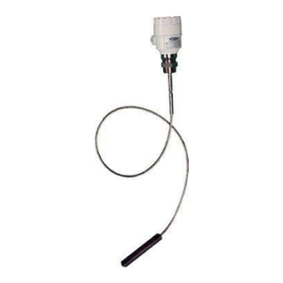
- Page 1 TDR-3000 Two-Wire Guided Wave Radar Installation & Operation Manual...
-
Page 3: Table Of Contents
Disconnect Requirements for Permanently Installed Equipment Conduit Cable Connection Power Supply Requirements Wiring TDR-3000 to Power Supply Figure 1: Basic 24V Wiring - TDR-3000 to Power Supply Figure 2. TDR-3000 to ORB Wiring Diagram VIII. SET-UP ..............................14 Programming Figure 3: Measurement Set-Up Guide IX. - Page 4 SAFETY SYMBOLS WARNING: IDENTIFIES CONDITIONS OR PROCEDURES, WHICH IF NOT FOLLOWED, COULD RESULT IN SERIOUS INJURY. RISK OF ELECTRICAL SHOCK. CAUTION: IDENTIFIES CONDITIONS OR PROCEDURES, WHICH IF NOT FOLLOWED, COULD RESULT IN SERIOUS DAMAGE OR FAILURE OF THE EQUIPMENT.
-
Page 5: Handling & Storage
This product can be recycled by specialized companies and must not be disposed of in a municipal collection site. If you do not have the means to dispose of properly, please contact Bindicator for return and disposal instructions or options. -
Page 6: General Safety
II. GENERAL SAFETY AUTHORIZED PERSONNEL All instructions described in the document must be performed by authorized and qualified service personnel only. Before installing the unit, please read these instructions and familiarize yourself with the requirements and functions of the device. The required personal protective equipment must always be worn when servicing this device. -
Page 7: Essential Health And Safety Requirements
V. PRODUCT DESCRIPTION FUNCTION The TDR-3000 two-wire guided microwave level transmitter uses the TDR (Time Domain Reflectometry) principle. The instrument sends low power nanosecond-wide pulses along an electrically conductive probe with a known propagation speed (the speed of light). As the pulse reaches the surface of the medium or phase of two liquids (altered dielectric constant ԑ... - Page 8 Gas (II 1G Ex ia IIB T6...T4 Ga) Voltage A = 12VDC to 36VDC, Ex 12VDC to 30VDC TDR-3000 Guided Wave Radar NOTES 1. Maximum probe length is 98.5 ft (30.0 m). 2. If no display is required, choose Display Type and Enclosure N 3.
-
Page 9: Technical Specifications
TECHNICAL SPECIFICATIONS FUNCTIONAL 24 VDC (12 to 36 VDC) Operating Power Ex Version: 24 VDC (12 to 30 VDC) -22° to 149° F (-30° to 65°C) Ambient Temperature -4° to 149°F (-20° to 65°C) with display Process Temperature -22° to 194°F (-30° to 90°C) - Page 10 = 30 V, i = 100 a, p Intrinsically safe data (II 1 0 Ex ia IIIC) 0.75 W teMperature data exploSiVe GaS atMoSpHere exploSiVe duSt atMoSpHere tdr-3000-a-G-_ tdr-3000 -a- d-_ iiic x ia x ia Maximum permissible process +80°c +90°c +100°c +80°c +90°c...
-
Page 11: Mechanical Installation
VI. MECHANICAL INSTALLATION WARNING: REMOVE POWER FROM THE UNIT BEFORE INSTALLING, REMOVING, OR MAKING ADJUSTMENTS. CAUTION: CARRY USING BOTH HANDS, LIFTING THE DEVICE CAREFULLY BY THE CONVERTER HOUSING. IF NECESSARY, USE LIFTING GEAR. NO ATTEMPT SHOULD BE MADE TO LIFT THE INSTRUMENT BY ITS PROBE. -
Page 12: General Installations
GENERAL INSTALLATION 1. Empty the vessel or at least reduce the material level below the length of the cable probe. 2. Determine location of where probe should be on the top of the tank. Consider the following: a. Cable probe should be at least 12 in (30 cm) away from any metal surface. -
Page 13: Installation Of Multiple Devices
INSTALLATION OF MULTIPLE DEVICES If two devices are being used in the same tank, the units should be mounted at a distance of at least 6.5 ft (2 m) away from each other. If not, interferences from the electromagnetic (EM) fields generated by both instruments may CABLE PROBE ALIGNMENT 6.5 ft (2 m) -
Page 14: Electrical Installation
VII. ELECTRICAL INSTALLATION WARNING: REMOVE POWER FROM THE UNIT BEFORE INSTALLING, REMOVING, OR MAKING ADJUSTMENTS. GENERAL SAFETY When using electrical equipment, you should always follow basic safety precautions, including the following: • The installation and wiring of this product must comply with all national, federal, state, municipal, and local codes that apply. -
Page 15: Power Supply Requirements
POWER SUPPLY REQUIREMENTS • 12 to 36 VDC WIRING TDR TO POWER SUPPLY 1. Turn off all power to unit. 2. Detach the cover of the unit. 3. Guide the cable into the housing through the cable gland 4. Remove a 0.16 in (4 mm) length of insulation from the wires and cut away the free part of the shielding. - Page 16 Figure 2: TDR to ORB Wiring Diagram TDR180003 Rev. I...
- Page 17 Non-Hazardous Duty Version Hazardous Duty Version TDR180003 Rev. I...
-
Page 18: Set-Up
VIII. SET- UP PROGRAMMING Units shipping directly from the factory have been programmed according to the customer requirements on the Application Data Sheet (ADS). If no changes to the tank have occurred, unit will be ready for use after installation and no additional programming is required. - Page 19 PROGRAMMING WITH THE DISPLAY PROGRAMMING WITH THE DISPLAY UNIT The most important parameters can be set with the display unit. By default, the display shows the primary measurement result (from which the output current is calculated). In addition to the measured value displayed in large numbers, a bar graph representing the value of the output current is also shown on the right.
- Page 20 The Behavior of the TDR while Programmed Manually By default, the TDR displays the main measurement data on the display (hereafter referred to as display). Enter the programming menu by pressing the E button. Use the / buttons to navigate through the menu items.
- Page 21 PROGRAMMING − Programming with the display unit Name (number), function Adjustable value range Description Default value 0...60 m It provides the basis for level measurement calculations. The distance between the plane of (0…200 ft) the lower sealing surface of the...
- Page 22 Name (number), function Adjustable value range Description Default value 0 (limiter off) or the minimum The maximum value of the measuring range of the device measuring distance. The distance can be limited with this parameter. between (P05) +5 cm and the probe Signals received beyond the set distance will not be processed.
- Page 23 Name (number), function Adjustable value range Description Default value Selectable values: The units that can actually be used (length, volume, weight) change − Metric (EU), European unit system according to the unit system set according to this parameter. When −...
- Page 24 Name (number), function Adjustable value range Description Default value Selectable values: The basic characteristic of the measured medium is set here. The − Liquid measuring capabilities of the device − Granular solid Operating mode (P00a), vary significantly depending on this characteristic of the medium (see −...
- Page 25 Name (number), function Adjustable value range Description Default value 0.1…900 m/h (0.33…2950 ft/h) The maximum rate of dropping in the tank during emptying. Entering it correctly makes the measurement Emptying speed (P27) 200 m/h (656 ft) more reliable during emptying.
- Page 26 Name (number), function Adjustable value range Description Default value Selectable values: Selecting a typical basic container − Output Conversion table (OCT) shape for volume measurement. The − Standing cylindrical tank with tank dimensions can be set using dome bottom parameters P41…...
- Page 27 Name (number), function Adjustable value range Description Default value 0…999 999 Typical dimensions in units of length for the tank type set in parameter Tank dimensions (P41…P45), for P40 for volume calculation. volume measurement SAP–300: no adjustment available If the device is set to weight...
-
Page 28: Maintenance
IX. MAINTENANCE The TDR-3000 does not require maintenance on a regular basis. In some very rare instances, however, the probe may need a cleaning from deposited material. This must be carried out gently, without damaging the probe. Repairs during or after the warranty period are carried out exclusively at the manufacturing facility. The equipment sent back for repairs should be cleaned or neutralized (disinfected) by the user. - Page 29 Current Output value < 4 mA Execute the calibration if you have The calibration of the current output is authorized access or contact Bindicator incorrect. Customer Support. This happens in case the range 4-20 mA/ error 22 mA is selected.
- Page 30 TDR180003 Rev. I...
- Page 31 150 Venture Boulevard Spartanburg, SC 29306 Tel: (800) 778-9242 2016 All rights reserved. Fax: (864) 574-8063 All data subject to change without notice. sales@bindicator.com www.bindicator.com TDR180003 Rev. I...
Need help?
Do you have a question about the TDR-3000 and is the answer not in the manual?
Questions and answers