Table of Contents
Advertisement
Quick Links
Advertisement
Table of Contents

Subscribe to Our Youtube Channel
Related Manuals for Yamaha SPX1000


Summary of Contents for Yamaha SPX1000
- Page 1 YAMAHA AUTHORIZED PRODUCT MANUAL Professional Multi-effect Processor...
- Page 2 YAMAHA Professional Multi-effect Processor Operation Manual...
- Page 3 -20 dBm or +4 dBm line levels + providing compatibility with a broader range of sound equipment. In order to fully take advantage of all the capability offered by the SPX1000 Professional Multi-effect Processor, we urge you to read this operation manual thoroughly— and keep it in a safe place for later reference.
-
Page 4: Table Of Contents
PRECAUTIONS 1: CONTROLS AND CONNECTIONS THE FRONT PANEL THE CONNECTOR PANEL 2: THE SPX1000 SYSTEM MEMORY CONFIGURATION INPUT MODE AND DIGITAL I/O CONFIGURATIONS INPUT MODES DIGITAL l/O MODES 3: GENERAL OPERATION SELECTING AN EFFECT/MEMORY LOCATION BYPASSING THE EFFECT ACCESSING & EDITING THE PROGRAM... -
Page 5: Early Ref
Since the SPX000 contains digital circuitry, it may cause interference and noise if placed too close to TV sets, radios or similar equipment. If such a problem does occur, move the SPX1000 further away from the affected equipment. 9. BACKUP BATTERY... -
Page 6: 1: Controls And Connections
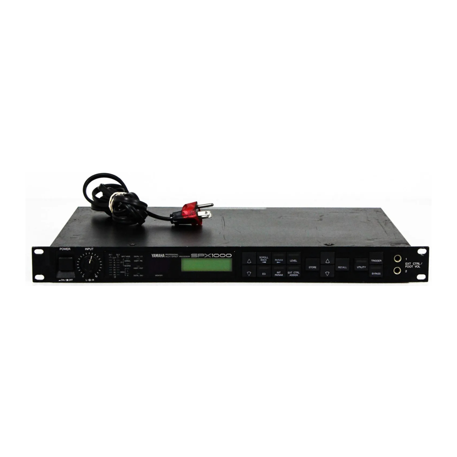
EXT CTRL/ FOOT VOL 1 and 2 jacks (21). These controllers can then be used to control the assigned parameter in real time. Yamaha FC7 Foot Controllers are recommended. • Details on page 10 Parameter... - Page 7 Program Select Keys These keys are used to select any of the SPX1000’s memory locations. The key increments (increases) the memory location number while the (decreases) the memory location number. Holding either key down causes continuous scrolling in the specified direction.
-
Page 8: The Connector Panel
THE CONNECTOR PANEL L(MONO) & R INPUT Connectors and Level Switch These are the analog stereo inputs to the SPX1000. The input jacks are standard 1/4” monaural phono types. The level switch selects either -20 dB or +4 dB nominal input level. -
Page 9: 2: The Spx1000 System
INPUT MODE AND DIGITAL I/O CONFIGURATIONS The SPX1000 offers a choice of input modes as well as analog and digital input/output configurations, providing extraordinary flexibility in “adapting” to various systems and requirements. -
Page 10: Digital L/O Modes
ANALOG In this mode the DIGITAL IN connector is inactive and the SPX1000 receives input via the analog INPUT L and R jacks. Both the analog OUTPUT L and R and DIGITAL OUT connectors are active so that the SPX1000’s output can be simultaneously fed to analog and digital equipment if required. - Page 11 When the SPX1000 clock (CLK) mode is switched from internal (INT) to external (EXT), or vice-versa, a noise pulse may appear at the outputs. This also occurs if the SPX1000 is switched from digital to analog input while CLK is set to EXT (CLK is automatically reset to INT in this case).
-
Page 12: 3: General Operation
OFF). Press the BYPASS key or footswitch a second time to turn off the BYPASS Key LED and turn the effect back 3: GENERAL OPERATION Each SPX1000 program has 4 different groups of parameters which are accessed by pressing the corresponding parameter select keys:... -
Page 13: Storing Effects
(41 – 99) simply by pressing the STORE key. EXTERNAL CONTROL ASSIGNMENT The SPX1000 allows two different parameters of a selected effect to be controlled by optional foot controllers (Yamaha FC7) connected to the front-panel EXT CTRL/FOOT VOL1 and 2 jacks. - Page 14 In the actual display, “XXXXXXXX” will be the name of the default parameter for the selected effect program. The EXT CTRL ASSIGN key can be used to scroll forward through the above parameters, and the SCROLL BACK key can be used to scroll backwards. 4.
-
Page 15: 4: The Programs & Parameters
This parameter adjusts the balance between the direct sound and effect signals. At 100% only the effect sound is delivered from the SPX1000 outputs, while at 0% only the direct sound is output. At a setting of 50%, the direct and effect sounds are output in approximately equal proportions. -
Page 16: Reverb Programs
Reverberation is the warm musical “ambience” you experience when listening to music in a hall or other properly- designed acoustic environment. The SPX1000 offers several different reverb effects, simulating types of reverberation you would experience in a hall (REV 1 HALL), in a smaller room... -
Page 17: Rev 4 Plate
The complexity of the many reflections that make up reverberation varies according to the shape of the room and its contents. In the SPX1000 the term “diffusion” refers to the complexity of these reflections. If the DIFFUSION parameter is set to “0,” minimum complexity and therefore a clearer, more straightforward reverb effect is produced. -
Page 18: Rev 5 Echo Room
Width fine: -100 – +100 This sets the value specified with WIDTH as the reference value (0) and is the parameter for fine adjustment. Height Fine: -100 – +100 This sets the value specified with HEIGHT as the reference value (0) and is the parameter for further fine adjustment. Depth Fine: -100 –... - Page 19 The complexity of the many reflections that make up reverberation varies according to the shape of the room and its contents. In the SPX1000 the term “diffusion” refers to the complexity of these reflections. If the DIFFUSION parameter is set to “0,” minimum complexity and therefore a clearer, more straightforward early reflection effect is produced.
-
Page 20: Delay Program
Density (DENSITY): EARLYREF.2: 1 – 3 GATE REVERB, REVERSE GATE : EARLY REF. Please note that the DENSITY parameter is not provided in the EARLY REF. 1 program. This parameter determines the density of the reverb reflections (i.e. the average amount of time between reflections). -
Page 21: Modulation Programs
After the initial delay produced by the INI DLY parameters, the time between subsequent repeats is determined by the left and right channel interval parameters. Left Channel Feedback Gain (Lch F.B): -99% — +99% Right Channel Feedback Gain (Rch F.B): -99% — +99% Individually set the amount of the left or right channel delay signal fed back to the input of the processor. -
Page 22: Noise Gate
PARAMETERS ACCESSED BY THE INT PARAM High-pass Filter Frequency (HPF FRQ): THRU, 32 Hz – 1.0 kHz Permits rolling off the low-frequency content of the reverb signal above the set frequency. The HPF is OFF when set to THRU. Low-pass Filter Frequency (LPF FRQ): 1 – 16 kHz, THRU Permits rolling off the high-frequency content of the reverb signal above the set frequency. -
Page 23: Pitch Change 1
PARAMETERS ACCESSED BY THE PARAM KEY 20. PITCH CHANGE 1 PITCH CHANGE 1 makes it possible to produce two independently pitch-shifted output notes in addition to the direct signal, so you can create three-part harmonies with a single input note. Both pitch-shifted notes appear at the center of the stereo sound field. -
Page 24: Stereo Pitch
PITCH parameter (the MIDI OUT terminal of the synthesizer must be connected to the SPX1000 MIDI IN terminal, and the SPX1000 must be set to receive on the MIDI channel on which the synthesizer is transmitting). - Page 25 ACCESSED BY THE INT PARAM KEY). Pitched playback of the sampled sound is possible by transmitting MIDI note ON messages to the SPX1000’s MIDI IN connector from a MIDI keyboard or other device (e.g. play a key on the keyboard).
-
Page 26: Freeze 2
(the MIDI OUT terminal of the synthesizer must be connected to the SPX1000 MIDI IN terminal, and the SPX1000 must be set to receive on the MIDI channel on which the synthesizer is transmitting). If, for example, the BASE KEY parameter is set to C4, pressing the C3 key on the synthesizer (C3 is one octave lower than C4) will cause the sampled sound to play one octave lower than its normal pitch. -
Page 27: Pan
PARAMETERS ACCESSED BY THE PARAM KEY 25. PAN This is a very sophisticated pan program that allows creation of “rotary” pan in addition to straightforward pan effects. Pan Type (TYPE): L R, L R, L R-TURN Determines the direction in which the sound sweeps across the stereo sound field. -
Page 28: Distortion Program
28. MULTI (CHO&REV) 29. MULTI (SYM+REV) 30. MULTI (EXC&REV) The SPX1000 multi-effect programs combine compressor, distortion, equalizer or dynamic filter (access via EQ key), reverb and chorus or exciter effects. Refer to the effect configuration diagram for each program to understand how the various effects are “connected.”... -
Page 29: Multi (Exc&Rev)
Chorus Frequency (CH. FRG): 0.05 – 40 Hz Chorus Delay Modulation Depth (DM DEPTH): 0% – 100% This sets the amount by which the delay time of one delay signal is varied in relation to the other, and thus the depth of the CHORUS effect. -
Page 30: Er + Rev
PARAMETERS ACCESSED BY THE INT PARAM Stereo or Mono x 2 Output (OUT MODE): ST, MONO When set to ST (stereo), the output of the left and right- channel processors are mixed and the output signal is delivered in stereo. When MONO x 2 is selected the left and right-channel processors are completely independent. -
Page 31: Chorus + Rev
PARAMETERS ACCESSED BY THE INT PARAM Stereo or Mono x 2 Output (OUT MODE): ST, MONO When set to ST (stereo), the outputs of the left and right- channel processors are mixed and the output signal is delivered in stereo. When MONO x 2 is selected the left and right-channel processors are completely independent. -
Page 32: Compressor & Expander Programs
PARAMETERS ACCESSED BY THE INT PARAM NOT AVAILABLE COMPRESSOR & EXPANDER PROGRAMS 36. COMPRESSOR This extremely versatile compressor program allows creation of a wide range of compression and limiting effects. It can simply be used to reduce the dynamic range of a signal, to smooth out the sound of an electric bass or add sustain to an electric guitar. -
Page 33: Lo Lvl Expander
37. LO LVL EXPANDER The EXPANDER program allows efficient suppression of low-level noise, contributing to a cleaner-sounding overall signal. This i a stereo expander in which the highest signal level – left- or right-channel - is used for gain control. NOTE: The EXPANDER program has no internal parameters. -
Page 34: 5: Utility Functions
The SPX1000 UTILITY key provides access to a number of important functions. Each press on the UTILITY key advances to the next function until the UTILITY mode is exited: TITLE EDIT INPUT MODE A/D I/O MODE DIGITAL IN ATT. USER ER EDIT... -
Page 35: Memory Protect
MIDI CONTROL & MIDI PGM CHANGE The SPX1000 makes it possible to select specific programs via external MIDI control. You can set up the SPX1000 for example, so that when you select a voice on a synthesizer the most appropriate effect for that voice is automatically selected. -
Page 36: Midi Ctrl Assign
MIDI assignments via the MIDI OUT terminal (The MIDI THRU/OUT terminal must be switched to MIDI). This permits transferring data to a second SPX1000 or storing the data on a MIDI data recorder. The SPX1000 automatically reloads data received from a MIDI data recorder into the appropriate keys to select either memory locations. -
Page 37: F.sw Memory Rcl
* A bulk dump will only be received by the SPX1000 if its MEMORY PROTECT function is OFF and the MIDI channel is the same as that of the transmitting equipment. Since bulk data from a second SPX1000, for example, is... -
Page 38: 6: Data & Specifications Add-1
6: DATA & SPECIFICATIONS ROM CONTENTS AND CONTROLLABLE PARAMETERS Add-1... - Page 39 Add-2...
- Page 40 Add-3...
- Page 41 Add-4...
- Page 42 Add-5...
- Page 43 Add-6...
- Page 44 Add-7...
- Page 45 Add-8...
- Page 46 Add-9...
- Page 47 Add-10...
- Page 48 Add-11...
- Page 49 Add-12...
- Page 50 Add-13...
- Page 51 Add-14...
-
Page 52: Midi Data Format Add-15
MIDI DATA FORMAT 1.Transmitting Conditions 2.Transmitting Data 2 . 1 System information 1 ) System Exclusive Messages MEMORY BULK DATA MIDI DATA FORMAT Transmission is enabled on the MIDI channel of the currently selected bank. Data is transmitted when BULK OUT 1 is displayed and BULK OUT is executed, and when the MEMORY BULK DUMP REQUEST message is received. - Page 53 Bank Program Change Chart Bulk Data Transmission is enabled on the MIDI channel of the currently selected bank. Data is transmitted when BULK OUT 1 is displayed and BULK OUT is executed, and when the PROGRAM CHANGE CHART BULK DUMP REQUEST message is received. The data to be transmitted is the program change chart (the chart showing the correspondence between program numbers and memory numbers).
- Page 54 User ER Pattern Bulk Data Transmission is enabled on the MIDI channel of the currently selected bank. Data is transmitted when BULK OUT 2 is displayed and BULK OUT is executed, and when the USER ER PATTERN BULK DUMP REQUEST message is received. The data to be transmitted is that of the indicated pattern number.
- Page 55 System Setup Bulk Data Transmission is enabled on the MIDI channel of the currently selected bank. Data is transmitted when BULK OUT 2 is displayed and BULK OUT is executed, and when the SYSTEM SETUP DATA DUMP REQUEST message is received. STATUS 11110000(F0H) ID No.
- Page 56 STATUS 11110000(F0H) ID No. 01000011(43H) SUB STATUS 0000nnnn(0nH) FORMAT No. 01111110(7EH) BYTE COUNT 00000010(02H) BYTE COUNT 00001010(0AH) 01001100(4CH)"L" 01001101(4DH)"M" 00100000(20H)SPACE 00100000(20H)SPACE 00111000(38H)"8" 00110011(33H)"3" 0 0 1 1 0 1 1 1 ( 3 7 H ) " 7 " 00111000(38H)"8" DATA NAME 01001101(4DH)"M"...
- Page 57 DATA Oddddddd Oddddddd CHECK SUM Oeeeeeee 11110111(F7H) 11110000(FOH) STATUS 11110111(F7H) 11110000(FOH) STATUS 11110111(F7H) STATUS 11110000(FOH) 11110111(F7H) STATUS 11110000(FOH) ID No. 0100001l(43H) SUB STATUS OOOOnnnn(OnH) FORMAT NO. 01111110(7EH) BYTE COUNT 00000001(01H) BYTE COUNT 01101110(6EH) 01001100(4CH)"L" 01001101(4DH)"M" 00100000(20H)SPACE 00100000(20H)SPACE 00111000(38H)"8" 00110011(33H)"3" 00110111(37H)"7" 00111000(38H)"8"...
- Page 58 STATUS 11110000 (F0H) ID No. 01000011 (43H) SUB STATUS 0000nnnn (0nH) FORMAT No. 01111110 (7EH) BYTE COUNT 00000000 (00H) BYTE COUNT 00011100 (1CH) 01001100 ( 4 C H ) " L " 01001101 ( 4 D H ) " M " 00100000 00100000 00111000 ( 3 8 H ) "...
- Page 59 3.Receiving Conditions 4 . Reception Data 4-1. Channel information 1 ) Channel voice messages Note On Reception is enabled on the MIDI channel of the currently selected bank. For programs of Memory Nos. 1 - 5 , 1 9 , and 2 6 , if the parameter of MIDI TRG. is ON, this is received as a trigger.
- Page 60 STATUS 1001nnnn ( 9 n H ) NOTE No. 0kkkkkkk VELOCITY ovvvvvvv Note Off This message is used when playback of the Memory No. 24 FREEZE 2 is finished. The velocity value is ignored. The reception conditions are the same as in Note On.
- Page 61 1100nnnn (CnH) STATUS 0ppppppp PROGRAM No. 4-2. System Information 1 ) System exclusive messages Memory Bulk Dump Request Reception is enabled on the MIDI channel of the currently selected bank. When this message is received, BULK OUT is executed for the program of the indicated memory number.
- Page 62 STATUS 11110000 (F0H) ID No. 01000011 (43H) SUB STATUS 0010nnnn (2nH) FORMAT No. 01111110 (7EH) 01001100 ( 4 C H ) " L " 01001101 ( 4 D H ) " M " 00100000 (20H)SPACE 00100000 (20H)SPACE 00111000 ( 3 8 H ) " 8 " 00110011 ( 3 3 H ) "...
- Page 63 STATUS 11110000 (F0H) ID No. 01000011 (43H) SUB STATUS 0010nnnn (2nH) FORMAT No. 01111110 (7EH) 01001100 ( 4 C H ) " L " 01001101 ( 4 D H ) " M " 00100000 00100000 00111000 ( 3 8 H ) " 8 " 00110011 ( 3 3 H ) "...
- Page 64 Bank Program Change Chart Bulk Data Same as "Bank Program Change Chart Bulk Data" for transmission. User ER Pattern Bulk Data Same as "User ER Pattern Bulk Data" for transmission. System Setup Bulk Data Same as "System Setup Bulk Data" for transmission. When receiving from the MIDI Data Filer MDF1, a computer, or other sources, the time interval between data exchanges (F7 ~ F0) with the other unit must be set to 30msec or longer.
- Page 65 YAMAHA [ Professional Multi-Effect Processor ] Model SPX1000 MIDI Implementation Chart Version : 1 . 0 Function . . . Basic Default Channel Changed Default Mode Messages Altered Note Number : True voice Velocity Note ON Note OFF After K e y ' s...
-
Page 66: Block Diagram Add
BLOCK DIAGRAM Add-29... -
Page 67: Dimensions Add
DIMENSIONS Add-30... -
Page 68: Specifications
SPECIFICATIONS ELECTRICAL CHARACTERRISTICS FREQ. RESPONSE DYNAMIC RANGE DISTORTION INPUT NUMBER OF CHANNEL NOMINAL LEVEL IMPEDANCE LEVEL CONTROL A/D CONVERSION NUMBER OF CHANNELS SAMPLING FREQ. QUANTIZATION D/A CONVERSION NUMBER OF CHANNELS SAMPLING FREQ. QUANTIZATION OUTPUT NUMBER OF CHANNEL NOMINAL LEVEL IMPEDANCE MEMORY PRESETS (ROM) USER MEMORY (RAM) - Page 69 Add-32...
- Page 70 Add-33...
- Page 71 DIO Mode Analog Post Digital Add-34...
- Page 72 Input Mode Stereo Normal Stereo Reverse Mono L Mono R Add-35...
- Page 73 Effect Mode Single No.1~27 Multi No.28~30 2ch ln No.31~35 Stereo No.36~40 Add-36...
- Page 74 Date: Memory Program Title REV 1 HALL REV 2 ROOM REV3 VOCAL REV 4 PLATE REV 5 ECHO ROOM EARLY REF. 1 EARLY REF. 2 EARLY REF. 3 GATE REVERB REVERSE GATE DELAY L, C, R STEREO ECHO STEREO FLANGE A STEREO FLANGE B CHORUS STEREO PHASING...
- Page 75 Add-38...
- Page 76 MIDI PROGRAM CHANGE NUMBER VS MEMORY (PROGRAM) NUMBER BANK: Date: Programmer: 1 1 0 1 1 1 1 1 2 1 1 3 1 1 4 1 1 5 1 1 6 1 1 7 1 1 8 1 1 9 Add-39...
- Page 78 YAMAHA YAMAHA CORPORATION P.O.Box 1, Hamamatsu, Japan 88 12 0.75 CR Printed in Japan...
- Page 79 YAMAHA Yamaha Corporation of America 6600 Orangethorpe Avenue, P.O. Box 6600, Buena Park, CA 90622-6600 1/24/97 24955...
Need help?
Do you have a question about the SPX1000 and is the answer not in the manual?
Questions and answers