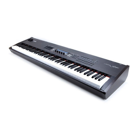
Yamaha S-80 Owner's Manual
Yamaha s-80 synthesizer: owners manual
Hide thumbs
Also See for S-80:
- Service manual (46 pages) ,
- Data list (41 pages) ,
- Performance list (1 page)
Table of Contents
Advertisement
Quick Links
Advertisement
Chapters
Table of Contents

Related Manuals for Yamaha S-80


Summary of Contents for Yamaha S-80
- Page 1 MUSIC SYNTHESIZER OWNER’S MANUAL OWNER’S MANUAL...
-
Page 2: Special Message Section
SPECIFICATIONS SUBJECT TO CHANGE: The information con- tained in this manual is believed to be correct at the time of printing. However, Yamaha reserves the right to change or modify any of the specifications without notice or obligation to update existing units. - Page 3 Yamaha service personnel.
-
Page 4: About This Manual
Thank you for purchasing the Yamaha S80 Music Synthesizer. Your new S80 synthesizer incorporates the highly-acclaimed AWM2 synthesis engine, allowing the creation of super-realistic sounds. keyboard. It also supports optional Plug-in Boards that provide other synthesis engines of your choice, enabling the production of cutting edge synthesizer sounds. -
Page 5: Table Of Contents
Table of Contents Basics Section The Controls & Connectors ...6 Before Use ...12 Power Supply ...12 Connections ...13 Powering Up...19 Basic Operations ...21 Selecting a Mode ...21 Selecting a Screen ...23 Entering Data...24 Demo Playback ...26 Voices and Performances ...27 Playing a Voice ...27 Playing a Performance...29 An Overview of the S80 ...31... -
Page 6: Basics Section
Basics Section The Controls & Connectors Front Panel GAIN A/D INPUT PITCH [VOLUME] Slider (Page 20) Adjusts the master volume. Move the slider upwards to raise the output level from the OUTPUT L/R jacks and the PHONES jack. Control Sliders (Page 61) In Master Keyboard Mode, the sliders can be used to control various functions assigned to them (as Control Change messages). - Page 7 3.3V CARD ASSIGNABLE KNOB SHIFT PAGE DATA PART/ELEMENT LCD (Liquid Crystal Display) This is a backlit 2-line display. [DATA] knob (Page 25) Use this to increase or decrease the value of the parameter at which the cursor is positioned. Knobs [A], [B], [C], [1] and [2] (Page 24) In each Play Mode, these knobs mainly control the functions respectively assigned to them.
- Page 8 [MASTER KEYBOARD] key (pages 57, 111) The S80 keyboard can work as MIDI master keyboard in Performance mode. When the key is pressed and switched on (the LED will light), the keyboard can play and control multiple MIDI sound modules connected to the S80. [EF BYPASS] key (Page 56) Enables/dsiables the Effect Bypass.
- Page 9 PRE1 PRE 2 PLG1 PLG2 DRUM DRUM QUICK ACCESS A. PIANO E. PIANO ORGAN GTR/BASS STRINGS BRASS SYNTH OTHER MEMORY keys (Pages 27, 29, 65, 109) Using one of these keys, you can select a Voice or Performance Memory. Press the [ENTER] key to select the Memory. In Performance Mode, the [EXT], [PLG1] and [PLG2] keys can be used to select the A/D Part, Plug-in 1 Part and Plug-in 2 Part.
-
Page 10: Rear Panel
Rear Panel POWER switch (Page 19) Use this to switch the synthesizer on or off. AC INLET terminal (Page 12) Plug the female end of the supplied AC power cord in here before plugging it into an AC wall outlet. POWER AC INLET FOOT CONTROLLER jack... - Page 11 HOST SELECT switch (Page 16) Select the type of computer connected to the synthesizer via the TO HOST connector . TO HOST terminal Connect a computer here using an optional serial computer cable (Page 16). OUTPUT L/MONO and R jack (Page 13) Line level audio signals are output via these phone jacks.
-
Page 12: Before Use
Use only the AC power cord supplied with the S80. If the supplied cord is lost or damaged and needs to be replaced, contact your Yamaha dealer. The use of an inappropriate replacement can pose a fire and shock hazard! The type of AC power cord provided with the S80 may be different depending on the country in which it is purchased (a third prong may be provided for grounding purposes). -
Page 13: Connections
Connections Connecting to External Audio Equipment Since the synthesizer has no built-in speakers, you need to monitor its sound output via external audio equipment. Alternatively, you could use a pair of headphones. There are several methods of connecting to external audio equipment, as described in the following illustrations. -
Page 14: Connecting A Microphone Or Other Audio Equipment
Headphones PHONES Connecting a pair of headphones does not affect audio output from the OUTPUT (L/MONO and R) jacks. You can monitor the same sounds via headphones and at the OUTPUT jacks. However, you cannot monitor the sounds from INDIVIDUAL OUTPUT 1 and 2 with headphones. Connecting a Microphone or Other Audio Equipment When an A/D Input Part is used in a Performance, signals from devices connected to either of these jacks can be input in mono. -
Page 15: Connecting External Midi Equipment
Connecting External MIDI Equipment You can connect an external MIDI device using a MIDI cable (available separately) and control it from this synthesizer. You can also use an external MIDI keyboard or sequencer to control the synthesizer’s internal sounds. This section introduces several different applications of MIDI. The HOST SELECT switch on the rear panel should be set to “MIDI.”... -
Page 16: Connecting To A Personal Computer
Controlling Another MIDI Device via MIDI THRU External MIDI sequencer MIDI OUT MIDI IN HOST SELECT PC-2 PC-1 MIDI With the above MIDI connections, you can send MIDI data from the MIDI OUT connector while MIDI data from the external sequencer can be sent to an external MIDI synthesizer via the MIDI THRU jack. - Page 17 2: MIDI Interface to MIDI IN and OUT Using the computer’s MIDI interface HOST SELECT PC-2 PC-1 MIDI Using an external MIDI interface HOST SELECT PC-2 PC-1 MIDI You will need to an appropriate MIDI application (sequencer, editor, etc.) for your computer platform. Serial cable MIDI IN MIDI OUT...
-
Page 18: Connecting Various Controllers
Connecting Various Controllers The S80 has several controller jacks on the rear panel, including FOOT SWITCH, SUSTAIN, FOOT CONTROLLER, FOOT VOLUME and BREATH. You can connect optional controllers like a Foot Switch (the FC4 or FC5), Foot Controller (the FC7) and Breath Controller (BC3, etc.) to control tone, volume, pitch and other parameters. -
Page 19: Powering Up
Powering Up Power-on Procedure When you have made all the necessary connections between your synthesizer and any other devices, make sure that all volume settings are turned down all the way to zero. Then turn on the every device in your setup in the order of MIDI masters (senders), MIDI slaves (receivers), then audio equipment (mixers, amplifiers, speakers, etc.). - Page 20 If you have a Memory Card inserted in the instrument’s CARD slot or an optional Plug-in Board installed, you may see other screens before the Voice or Performance Play Mode screen is displayed. If a previously used Memory Card is inserted in the CARD slot, you will see a screen while files in EXT Memory are being loaded.
-
Page 21: Basic Operations
Basic Operations This section gives some basic explanations about operating the synthesizer. Selecting a Mode There are several operation Modes — Voice Play Mode, Performance Play Mode, etc. — each of which enables you to work efficiently with the synthesizer’s various functions. An overview of each Mode is given on Page 35. -
Page 22: Job Modes
Job Modes 5 Utility Mode (Page 134) When in each Play Mode, you can swiftly switch to each Press the [UTILITY] key (its respective Job Mode by simply LED will light) to enter Utility pressing the [JOB] key (its LED Mode. -
Page 23: Selecting A Screen
Selecting a Screen You can switch between screens using the [PAGE] knob and pressing [SHIFT], [PROGRAM/PART], [EXIT] and [ENTER] keys. [PAGE] Knob Usually, there are several screens and sub-screens in each Mode. Use the [PAGE] knob to switch between screens. SHIFT PAGE Previous screen... -
Page 24: Entering Data
[ENTER] Key Normally, the [ENTER] key is used to apply parameter settings. In some cases, however, the following screen appears prompting you to press the [ENTER] key. MASTER BYPASS KEYBOARD EXIT ENTER DEC/NO INC/YES The [ENTER] key has other functions, as described in other sections in this manual. -
Page 25: Data] Knob
[DATA] Knob Use this knob to change the value of the parameter at which the cursor is positioned. Turn the knob clockwise to increment the value one click (step) at a time, or turn it anti-clockwise decrement it. SHIFT PAGE PART/ELEMENT Moving the Cursor Turn the [DATA] knob clockwise or anti-... -
Page 26: Demo Playback
Demo Playback Several demo songs are supplied with this synthesizer. You can play them back as follows. Make sure synthesizer is ready for playback. Details are given in the section “Before Use” on Page 12. At the “SEQ Demo” screen, any data in the instrument’s internal memory (System, Internal Voices or the like) will be overwritten by the data for the demo song. -
Page 27: Voices And Performances
Voices and Performances Playing a Voice Based on an AWM2 synthesis engine, this synthesizer offers various kinds of preset Voices (256 Normal Voices and 8 Drum Voices). You can also create your original Voices and store them into the instrument’s internal memory (INT) or an external Memory Card (EXT). The internal and external memory can each contain up to 128 Normal Voices and 2 Drum Voices. - Page 28 The Drum Voices are held in separate areas of each Memory, and are accessed as follows. • To access the Preset Drum Memories (PRE:DR1 ~ DR8): Press the MEMORY [PRE2] key while holding down the MEMORY [PRE1] key. • To access the User Drum Memories (INT:DR1/2, EXT:DR1/2): Press the MEMORY [EXT] key while holding down the MEMORY [INT] key.
-
Page 29: Playing A Performance
Playing a Performance In Performance Play Mode, you can select and play any of 128 internal and 64 external (Memory Card) Performances. A Performance is a set of Voices used with the built-in (or an external) sequencer. Performances also let you set the synthesizer up for multitimbral operation. Each Performance can contain up to 16 Parts assigned to different Voices, plus extra Parts for A/D INPUT and Plug-in Boards. - Page 30 3 Select a Performance Number using the [DATA] knob or the [INC/YES] and [DEC/NO] keys Turn the [DATA] knob clockwise or press the [INC/YES] key to increment the Performance Number. Turn it anti-clockwise or press the [DEC/NO] key to decrement the Performance Number.
-
Page 31: An Overview Of The S80
An Overview of the S80 In this section, an overview of the many features of the S80 is given. The S80 hardware is made up of a number of sections, as shown in the following diagram. Sequencer Section Song File Playback Arpeggiator Controller Section This section consists of the keyboard, Pitch Bend and Modulation Wheels, Control Sliders, Assignable... -
Page 32: Tone Generator Section
AWM2 (Advanced Wave Memory 2) is a synthesis system based on the use of sampled waveforms, and is used in many Yamaha synthesizers. For extra realism, each AWM2 Voice uses multiple samples of a real instrument’s waveform. Furthermore, a wide variety of envelope generator, filter, modulation, and other parameters can be applied to the basic waveform. -
Page 33: Maximum Polyphony
More Plug-in Boards will be available in future. About MODULAR SYNTHESIS PLUG-IN SYSTEM The Yamaha Modular Synthesis Plug-in System offers powerful expansion and upgrade capabilities for Modular Synthesis-Plug-in-compatible synthesizers, tone generators and sound cards. This enables you to easily and effectively take advantage of the latest and most sophisticated synthesizer and effects technology, allowing you to keep pace with the rapid and multi-faceted advances in modern music production. -
Page 34: Effects Section
Effects Section The effects can be used to change the sound of a Voice or Performance. There are two Insertion Effect Units plus a Reverb Unit (with 12 types of reverb) and a Chorus Unit (with 23 types of chorus). Each of the Insertion Effect units offers a variety of effects, and the units themselves can be connected in parallel or in series. -
Page 35: About The Modes
About the Modes The S80 has various Modes which you can select according to the task you wish to perform. Voice Mode Voice Play Mode Voice Edit Mode Voice Job Mode Utility Mode Utility Job Mode Card Mode Voice Mode (Page 64) Voice Play Mode Normal Voices and Drum Voices can be played in this Mode. -
Page 36: Voices
Voices A Voice is a sound created from the many parameters set in the synthesizer. In Voice Play Mode, you can select and play any of these Voices. In Performance Play Mode, several different Voices (known as Parts in this Mode) can be layered and played simultaneously via keyboard or a sequencer. Four groups of Voices are available (Preset 1, Preset 2, Internal and External). -
Page 37: An Overview Of Voices/Waves
An Overview of Voices/Waves Each Voice consists of up of up to four Elements. Each Element itself uses a high-quality waveform. Voice Element 1~4 Internally, there are two Voice Types: Normal Voices and Drum Voices. Normal Voices are mainly musical instrument-type sounds that can be played over the range of the keyboard. Drum Voices are mainly percussion/drum sounds that are assigned to individual notes on the keyboard. -
Page 38: Waves
Waves Waves are waveforms used as Elements that make up a Voice. 553 high quality preset Waves are available. As shown in the following illustration, when creating a Voice, you can select the Wave to be used as an Element and then set its level, pitch, tone and other parameters. wave 1~553 Element1 Element2... -
Page 39: Performances
Performances A Performance consists of up to 19 Parts, each of which can a Normal Voice, Drum Voice, A/D Input Part or Plug-in 1/2 Part. By switching on the Layer Switch parameter for different Parts (up to four), you can play back rich layered sounds in Performance Play Mode. You can also create splits so that different Parts are assigned to different areas of the keyboard. -
Page 40: Ideal For Playing Live
Ideal for Playing Live Many features of this synthesizer make it ideal for live performances. These features are explained here. Using the Arpeggiator (Page 41) A wide variety of arpeggio patterns can be created automatically by just holding down a set of notes on the keyboard. -
Page 41: Arpeggiator
1 Arpeggiator The arpeggiator is particularly suited to dance/techno music genres. You can assign any of 128 Arpeggio Types to each Voice, Performance and adjust the tempo. You can also set the Arpeggio Mode (the way in which the arpeggio is played back when you press a note) and Play Effects to create your own original grooves. -
Page 42: Using The Arpeggiator
Using the Arpeggiator Use Knob [1] to set the Arpeggiator Switch parameter to “on.” You can hold down multiple notes to create complex arpeggio patterns. SHIFT PAGE PART/ELEMENT When the arpeggiator is switched on, the notes you play (and hold down) on the keyboard will be arpeggiated using the currently selected Voice or Performance, and according to the Arpeggio Type, Tempo and Note Limit settings. -
Page 43: Using Controllers
Following the example in this manual, if you select Voice Program Number 098(G02) of INT, Portamento is already set for this Voice. Use the PORTAMENTO knob and [ON/OFF] keys to change the portamento time and switch portamento on/off (Page 74). Using the Arpeggiator Hold With Arpeggiator Hold switched on, the arpeggiator will continue to play back, even after... -
Page 44: Foot Controller
The parameter assigned to the Foot Switch is set in the CTRL Other screen of Utility Mode (Pages 48, 136). Sustain With an optional Yamaha FC4 or FC5 Foot Switch connected to the SUSTAIN jack (Page 18) on the rear panel. This is useful when playing piano- type sounds. -
Page 45: Control Sets
Aftertouch Aftertouch lets you, for example, add vibrato to a sound by applying further pressure to a note on the keyboard while it is being held down. This allows real-time expression and control. Aftertouch can be used to control a wide variety of parameters (Page 74). - Page 46 Control Sets and External MIDI Control In a Control Set, the controllers are assigned to the internal parameters of the synthesizer. However, some controllers were originally designed for a particular purpose, and send pre-defined MIDI Control Change messages when used, regardless of their Control Set allocations within the synthesizer.
- Page 47 Assigning Parameters to Knobs [1] and [2] The following procedure explains how you can assign a desired parameter to Knob [1] or [2]. You can assign controllers to each Voice (or Part in a Performance). Control Settings can be assigned as a Control Set, and a each Controller can be used to control multiple parameters (although this varies according to the type of Voice).
- Page 48 Controlling Parameters by Foot Controller By connecting an optional Foot Controller (such as the FC7) to the FOOT CONTROLLER jack on the rear panel of the synthesizer, you can control various parameters by foot without having to use your hands. In the following example, we introduce how to set up Foot Controller to work as Modulation Wheel.
- Page 49 1 Press the [UTILITY] key to enter Utility Mode. MODE VOICE PERFORM STORE UTILITY CARD PLAY PLAY/ EDIT STOP COMPARE 2 Use the [PAGE] knob to switch to the CTRL Other (System Control Other) screen. SHIFT PAGE PART/ELEMENT 3 Use Knob [B] to select "099:PC Inc" (Program Change Increment).
-
Page 50: Voice Edit
Voice Edit There are 256 Normal Voice presets and 8 Drum Voice presets. You can edit these to create new Voices, or build completely new Voices from scratch. You can then store up to 128 of these new/edited Normal Voices and up to 2 new/edited Drum Voices to internal user memory or external Memory Card. - Page 51 Element1 Element2 COMMON Element3 Element4 Selecting Elements In Voice Edit Mode, you can select the Element to edit by pressing the respective BANK key ([A] to [D]). When you select an Element, the cursor moves to the respective Element Number. Example: When “Element 2”...
- Page 52 • QED (Common Quick Edit) These parameters mostly control the volume and tone of the Voice and you can easily change the overall sound. • ARP (Common Arpeggio) By setting these parameters, you can control how the Voice is arpeggiated. Details about how to use the Arpeggiator are given on Page 41.
- Page 53 Element 3 Velocity Element 2 Element 1 Element 4 5 PCH (Pitch) and PEG (Pitch EG) Screens Set the basic pitch parameters for each Element. You can detune Elements, apply Pitch Scaling and so on. Also, by setting the PEG (Pitch Envelope Generator), you can control how the pitch changes over time.
- Page 54 7 AMP (Amplitude) and AEG (Amplitude EG) Screens Set the volume of each Element after the OSC (Oscillator), PITCH and FILT (Filter) parameters have been applied, and also the final overall volume of the signal sent to the outputs. The signal of each Element is sent at the specified volume to the next Effect Unit.
-
Page 55: Effects
Effects In the final stages of programming, you can set the effects parameters to further change the sound’s character. To generalize, System Effects apply to the overall sound, whether it is a Voice, a Performance, a Song, etc. Insertion Effects, on the other hand, can be applied individually to each Voice. -
Page 56: Effect Bypass
Mixer Insertion Effect Part 1~16 Effect Bypass You can temporarily switch effects off or on by pressing the [EF BYPASS] key. To use this function, you will need to specify the effect to be bypassed in the MSTR EF Bypass screen of Utility Mode (Page 135). -
Page 57: Using As A Master Keyboard (Performance Mode)
Using as a Master Keyboard (Performance Mode) As previously explained, your Synthesizer provides several convenient features that you can make use of in a live show or the like. Here we introduce some examples to combine those features to meet your specific purposes. The S80 has special settings in Performance Mode so that you can use the instrument as MIDI master keyboard. - Page 58 9Turn the [PAGE] knob and open the ARP Type (Arpeggio Type) page. Set “on” for “Switch.” In steps 6 to 9, you now complete settings for the lower range for Arpeggiator performance. It will play in a Voice assigned to Part 1 based on MIDI Receive channel 1.
- Page 59 4Select one of “Zone01” to “Zone04” using the Knob [A]. As we have selected “4zone” for the Mode parameter, you can now select setting screens for four Zones. Select “Zone01” to get started with the settings. You can also use the BANK [A] to [D] keys to respectively select “Zone01”...
- Page 60 %As in the same manner in steps ! to #, set up for Zone 3. Turn the Knob [A] and select “Part03”. Next go to the Mix Voice (MIX Vce) page using the [PAGE] knob, and select a Voice for manual solo performance. Then, use the [PAGE] knob to open the Layer Mode (LYR Mode) page and set the MIDI receive channel (RcvCh) to “3”.
- Page 61 8As in the same manner in steps 5 to 7, set up for the Upper Part. Select “PartP1” for the Lower Part, go to the Mix Voice (MIX Vce) page using the [PAGE] knob, and select another Voice (Plug-in Voice) for the Lower Part. Also, go to the Layer Mode (LYR Mode) page to set the Layer Switch (Layer) to “off”...
-
Page 62: Using As A Multitimbral Tone Generator (Performance Mode)
Using as a Multitimbral Tone Generator (Performance Mode) Performance Mode lets you use your synthesizer as a multitimbral tone generator for use with computer- based music software or external sequencers. If each track in a song file uses a different MIDI channel, then the Parts in a Performance can be each assigned to those MIDI channels correspondingly. -
Page 63: Using The A/D Input Part
Performing Live while Playing Back a Song File While playing back the song file with the piano, bass and drum Parts assigned earlier, you can set up the Performance so that you can also play another Part live. Performance Part 1 Solo-type Voice Song File Layer=on... -
Page 64: Reference Section
Reference Section Voice Mode Voice Play This mode is used for playing individual voices stored as 256 on-board presets, as well as the Internal (User) Voices, External Voices on Memory Card, and Plug-in Board Voices (optional). This section explains how to select and play voices. -
Page 65: Voice Name
3.Voice Category/Name Voice Category The two characters to the left of the Voice Name denote the category of instrument or sound to which the voice belongs. Details about Category names are given on Page 70. Voice Name This consists of up to 10 characters. 4.Knob Parameter Display This shows the function assigned to each knob ([A] to [C] and [1]/[2]). -
Page 66: Selecting Preset Drums (Pre:dr1~Dr)
Using [INC/YES] and [DEC/NO] Keys Press the [INC/YES] key to select the next Voice and the [DEC/NO] key to select the previous one. DEC/NO INC/YES Previous Number Next Number The voice is selected by pressing just the [INC/YES] or [DEC/NO] key. This method is useful when selecting a Voice that is located near the currently selected Voice. -
Page 67: Using The Voice Category Search
PRE1 PRE 2 DRUM DRUM • Press the MEMORY [EXT] key while holding down the MEMORY [INT] key (or vice versa) to select the Internal/External (INT/EXT) Memory of the User Drum Voice. Then use the [INC/YES] or [DEC/NO] keys to select the Drum Voice. PRE1 PRE 2 DRUM... -
Page 68: Voice Edit
within the current Voice Memory, [------] is displayed in the LCD and you will not be able to use Knob [2]. Press the [ENTER] key to start searching in the next Memory. Using the Quick Access Using Quick Access, you can quickly select any of 12 types of Preset Voices and 4 types of Internal Voices (at their factory default settings) in each Bank according to their Categories. - Page 69 Element1 Element2 COMMON Element3 Element4 Indicator If you alter any parameters in Voice Edit Mode, the indicator will be displayed in the top left of the screen. This gives a quick indication that the current voice has been modified but not yet stored. Edit indicator Even if you exit to Voice Play Mode, the edited settings for the current Voice will not be lost so long...
-
Page 70: Common General
FLT Sens (Filter Sensitivity) FEG VelSens (FEG Velocity Sensitivity) FEG Time FEG Level FEG Release FLT KeyFlw (Filter Key Follow) FLT Scale (Filter Scale Break Point) FLT Scale (Filter Scale Offset) Element Amplitude AEG VelSens (AEG Velocity Sensitivity) AEG Time AEG Level AEG Release AMP KeyFlw (AMP Key Follow) -
Page 71: Gen Other (General Other)
GEN Other (General Other) There are various parameters for Micro Tuning and for controlling how the generated sound is output. Mode Select monophonic or polyphonic playback. Select whether the Voice is played back monophonically (single notes only) or polyphonically (multiple simultaneous notes). Settings: mono, poly Assign If you set Key Assign to “single,”... -
Page 72: Qed Filter (Quick Edit Filter)
QED Filter (Quick Edit Filter) These parameters control filters which affect the tonal quality of the Voice. If you are using LPF (Low Pass Filter) and HPF (High Pass Filter) combined together, the parameters in the QED Filter page only affects LPF. Cutoff Set the cutoff frequency. -
Page 73: Arp Limit (Arpeggio Note Limit)
Switch Switch the Arpeggiator on or off. Settings: off, on Hold Switch the Arpeggiator Hold on or off. Settings: syncoff (see below), off, on syncoff The first time you press a key, the first note of the arpeggiator pattern is played. From the second and subsequent key presses, the arpeggiator note that is played back will depend on the arpeggiator tempo and the timing of the arpeggio pattern. -
Page 74: Common Controller
Common Controller There are eight Control Settings. You can set the Controller parameters for Portamento, the Pitch Bend Wheel, and for each Element in a Voice. CTL Portamento CTL Bend (Pitch Bend) CTL Set1 (Control Set 1) CTL Set2 (Control Set 2) CTL Set3 (Control Set 3) CTL Set4 (Control Set 4) CTL Set5 (Control Set 5) -
Page 75: Common Lfo (Low Frequency Oscillator)
Dest (Destination) Set the parameter to be controlled by the Control Set in Src. Settings: (see the separate “Controls” list) ElemSw (Element Switch) Select whether the Controller will affect each individual Element. Move the cursor (blinking) using Knob [1] and use the [DATA] knob or the [INC/YES] and [DEC/NO] keys to enable/disable the Elements which the Controller will affect. - Page 76 trpzd S/H 1 S/H 2 Speed Set the speed of the LFO Wave modulation. Higher values mean faster modulation speeds. Settings: 0 ~ 63, 16th (16th note), 16th/3 (16th note- triplet), 16th. (16th dot-note), 8th (8th note), 8th/3 (8th note-triplet), 8th. (8th dot-note), 4th (4th note), 4th/3 (4th note-triplet), 4th.
-
Page 77: Lfo Fade
LFO Fade Delay Set the delay time before the LFO comes into effect. A higher value means a longer delay time. Settings: 0 ~ 127 Short delay Key on Long delay Key on FadeIn (Fade-In) Set the time taken for the LFO effect to be faded in (after the Delay time has elapsed). -
Page 78: Common Effect
Dest (Destination) Set the parameters which will be controlled (modulated) by the LFO Wave. Settings: AMD, PMD, FMD, RESO (Resonance), PAN, ELFOSpd (Element LFO Speed) ElemSw (Element Switch) Select whether to allow variations in the LFO Wave for each Element. Move the cursor (blinking) using Knob [1] and use the [DATA] knob or the [INC/YES] and [DEC/NO] keys to enable/disable LFO Wave variations for Elements 1 to 4. -
Page 79: Eff Rev (Reverb)
EFF Rev (Reverb) You can select the Reverb Effect Type, then press the [ENTER] key to set its parameters. Type (Reverb Effect Type) Set the Reverb Effect Type. Settings: Details are given in the Effect Types list of the separate Data List. Return Set the Return level of the Reverb Effect. -
Page 80: Osc Pan (Oscillator Pan)
Long Delay Key on InsEF (Insertion Effect) Set the Insertion Effect to which the output signal from each Element is sent. The Insertion Effect is bypassed if you select Thru. Settings: thru, ins1 (Insertion Effect 1), ins2 (Insertion Effect 2) OSC Pan (Oscillator Pan) You can set the following Pan parameters for each Element in the Voice. -
Page 81: Peg Velsens (Peg Velocity Sensitivity)
Coarse Adjust the pitch of each Element in semitones. Settings: -48 ~ 0 ~ +48 Fine Fine-tune the pitch of each Element. Settings: -64 ~ 0 ~ +63 Random Set the amount by which the pitch of each Element is varied at random for each note you press. A setting of zero means the original pitch is not changed. -
Page 82: Pch Scale (Pitch Scale)
Time (Release Time) Set the Release Time. Settings: 0 ~ 127 Level (Release Level) Set the Release Level. Settings: -128 ~ 0 ~ +127 (-4800 cents ~ 0 ~ +4800 cents) Pitch Envelope Generator Settings There are five Time settings (controlling the speed of changes to the sound) and five Level settings (controlling the pitch). -
Page 83: Element Filter
Element Filter You can set Filter parameters to change the tonal characteristics of each Element. The following ten screens are available. FLT Type (Filter Type) FLT HPF (High Pass Filter) FLT Sens (Filter Sensitivity) FEG VelSens (FEG Velocity Sensitivity) FEG Time FEG Level FEG Release FLT KeyFlw (Filter Key Follow) - Page 84 • HPF (High Pass Filter) This only passes signals above the Cutoff frequency. You can then use the Reso (Resonance) parameter to add further character to the sound. Two types of HPF are available. Level -12db/oct -24db/oct Cutoff HPF24D (High Pass Filter 24dB/oct Digital), A 4-pole (-24db/oct) dynamic HPF with a strong Resonance.
-
Page 85: Feg Velsens (Feg Velocity Sensitivity)
Cutoff Set the Cutoff frequency. This is used as the basic frequency for the selected Filter Type. Settings: 0 ~ 255 Reso (Resonance)/Band/Width This parameter’s function varies according to the selected Filter Type. If an LPF or HPF has been selected, this parameter is used to set the Resonance. - Page 86 FEG Time You can set various Time parameters for the Filter Envelope Generator (FEG). Combined with the FEG Level and FEG Release settings, these can be used control the change in sound from the moment a note is pressed on the keyboard to the moment it is released. You can set different values for each Element.
-
Page 87: Flt Scale (Filter Scale Offset)
Cutoff Set the Filter Key Follow ratio (the amount by which the Filter Cutoff varies according to note position) for each Element. A Center Key setting of C3 is used as the basic setting by the Cutoff parameter. A positive setting will lower the Cutoff frequency for lower notes and raise it for higher notes. -
Page 88: Element Amplitude
Element Amplitude You can set Amplitude parameters to affect the output level of each Element. The following seven screens are available. AEG VelSens (AEG Velocity Sensitivity) AEG Time AEG Level AEG Release AMP KeyFlw (AMP Key Follow) AMP Scale (AMP Scale Break Point) AMP Scale (AMP Scale Offset) AEG VelSens (AEG Velocity Sensitivity) You can set the sensitivity of the Amplitude Envelope... -
Page 89: Amp Keyflw (Amp Key Follow)
Level (Release Level) This shows the Release Level. (Fixed at zero.) Amplitude Envelope Generator Settings There are four Time settings (controlling the speed of changes in output level) and five Level settings (controlling the output level). The output level changes from the Initial Level to the Attack Level (127) within the Attack Time. -
Page 90: Element Lfo (Low Frequency Oscillator)
AMP Scale (AMP Scaling Break Point) You can set four Amplitude Scaling Break Points for each Element. Amplitude Scaling controls the amplitude according to the positions of the notes on the keyboard. There are four Break Points used to divide and assign different settings across the keyboard. -
Page 91: Element Eq (Equalizer)
Speed Set the speed of the LFO waveform. A larger setting means a faster speed. Settings: 0 ~ 63 Speed = Fast Speed = Slow KeySync Switch Key Sync on or off. When switched on, the LFO waveform is reset every time a note is played. Settings: off, on Sync off Sync on... -
Page 92: Drum Voices
LoFreq (Low Frequency) Set the low frequency of the Shelving filter. Frequencies below this point are attenuated or boosted by the Low Gain parameter. Settings: 50.1Hz ~ 2.00kHz LoGain (Low Gain) Set the amount by which the frequencies below the Low Frequency setting are attenuated or boosted. -
Page 93: Drum Common General
Drum Key Pitch PCH Tune (Pitch Tune) Drum Key Filter FLT Cutoff (Filter Cutoff) Drum Key Amplitude AMP AEG (Amplitude Envelope Generator) AMP VelSens (Amplitude Velocity Sensitivity) Drum Key EQ (Equalizer) EQ Type (EQ Type) EQ Param (EQ Parameter) Drum Common Edit and Drum Key Edit Each Drum Voice consists of multiple Waves or Normal Voices assigned to notes across the keyboard (C0 to C6) (Page 37). -
Page 94: Drum Key Osc (Oscillator)
Attack Set the Attack time (the time from the moment the note is pressed to the point at which the maximum sound output level is reached). Settings: -64 ~ 0 ~ +63 Decay Set the Decay time (the time from the point of maximum sound output level to the point at which it has completely faded out). - Page 95 OSC Out (Oscillator Out) Set the Wave or Normal Voice output settings for each Drum Key. Level Set the output level for each Wave or Normal Voice. This can be used to adjust the output of each Drum Key. Settings: 0 ~ 127 InsEF (Insertion Effect) Select the Insertion Effect to which the output of each Drum Key will be sent.
-
Page 96: Drum Key Pitch
RcvNtOff (Receive Note Off) Select whether MIDI Note Off messages are received by each Drum Key. Settings: off, on This parameter depends on the Type of Drum Key Wave chosen in the OSC Wave screen. AltGrp (Alternate Group) Set the Alternate Group to which the Wave is assigned. -
Page 97: Amp Aeg (Amplitude Envelope Generator)
AMP AEG (Amplitude Envelope Generator) The Amplitude Envelope Generator controls the change in amplitude from the moment a note in pressed on the keyboard to the moment it is released. By setting the Attack Time, Decay 1 Time and the Decay 1/2 Level, you can determine how fast the sound reaches its peak amplitude and how it fades out. -
Page 98: Plug-In Voices
Plug-in Voices The Voices held on Plug-in Boards (Single Part) are known as Board Voices. A Plug-in Voice is a Board Voice that has been processed in the synthesizer in Voice Edit Mode. There are six Common Edit screens and four screens for editing the Element of a Plug-in Voice. -
Page 99: Plug-In Common General
Plug-in Common General The General parameters are shown in the following two screens. GEN Name (General Name) GEN Other (General Other) GEN Name (General Name) The parameters and settings are the same as for Normal Voices. See Page 70 for further details. GEN Other (General Other) There are parameters available for Plug-in Board. -
Page 100: Plug-In Common Controller
Plug-in Common Controller You can set Pitch Bend Wheel, Modulation Wheel and other Controller parameters for the Plug-in Voices in the following nine screens. CTL Pitch (Pitch Bend) CTL Set1 (Control Set 1) CTL Set2 (Control Set 2) CTL MW Control (MW Control Depth) CTL MW Modulation (MW Modulation Depth) CTL AT Control (AT Control Depth) CTL AT Modulation (AT Modulation Depth) -
Page 101: Ctl At Modulation
CTL AT Modulation (AT Modulation Depth) Here, you can set the depth of control that keyboard aftertouch has over the pitch, filter and amplitude modulation of the Plug-in Voice. PMod (Pitch Modulation Depth) Set the depth of control that keyboard aftertouch has over the filter pitch modulation. -
Page 102: Osc Assign (Oscillator Assign)
Delay Set the delay time between the moment you press a note on the keyboard and the moment the LFO comes into effect. As shown in the illustration, a positive setting will lengthen the delay and a negative setting will shorten it. Settings: -64 ~ 0 ~ +63 Short Delay Key on... -
Page 103: Eq Param (Eq Parameter)
PCH PEG (Pitch Envelope Generator) InitLvl (Initial Level) Set the Initial Level. Settings: -64 ~ 0 ~ +63 Attack Set the Attack Time. Settings: -64 ~ 0 ~ +63 Release Set the Release Time. Settings: -64 ~ 0 ~ +63 Level Set the Release Level. -
Page 104: Editing Plug-In Board Voices
Editing Plug-in Board Voices Plug-in Voices are based on Board Voices. However, the Board Voices themselves can be edited via computer, using the included editor software. Different editors are available for different Plug-in Boards. When using the editor while the synthesizer is in Voice Mode, set the “Part No.”... -
Page 105: Voice Job Mode
Voice Job Mode You can perform various operations (Jobs) in Voice Job Mode. For example, you can “Initialize” Voices (including those currently being edited) or “Recall” previous edits. When you enter Voice Job Mode, you will first see the Initialize screen. The following four screens are available for each Voice Job. -
Page 106: Voice Store
1 Source Voice Memory Select the Voice Memory containing the Voice (source) from which you will copy parameter settings. Settings: PRE1/2 (Preset 1/2), INT (Internal Normal), EXT (External Normal), PLG1/2 (Plug-in 1/2), PRE (Preset Drum), INT (Internal Drum), EXT (External Drum) 2 Source Voice Number Select the Voice Number of the source Voice. -
Page 107: Performance Mode
Performance Mode Performance Play In Performance Play Mode, multiple Voices (up to four Parts) can be layered to create thick sounds which you can play in real-time or using a sequencer. In Performance Mode, up to 19 Parts can be combined in a single Performance, including Voices for the 16 Parts plus A/D Input and Plug-in 1/2 Parts. -
Page 108: Setting/Viewing Knob Parameters
Performance Program Performance Bank Number Number Number 3. Performance Category/Name Performance Category A two-letter abbreviation of the Performance Category is shown to the left of the Performance Name. This gives you a rough idea of the Performance’s sound. Performance Name The name of a Performance can consist of up to 10 characters. -
Page 109: Multi Edit
Performance Program Selection There are four ways in which you can select a Performance. Using the BANK/PROGRAM keys Using the [DEC/NO] and [INC/YES] keys Using the [DATA] knob Using the Category Search Using the [INC/YES] and [DEC/NO] keys, the [DATA] knob or the Category Search function is the same as selecting the Voice directly in Voice Play Mode. - Page 110 4Repeat steps 2 and 3 for each of the other Parts. To avoid losing the settings, make sure you store the Performance before exiting to another Mode or selecting another Performance. Details about how to store Performances are given on Page 131. Reading the Displayed Settings Screens 3 to 7 have the following functions.
-
Page 111: Performance Edit
Performance Edit You can set Performance Edit parameters. These can roughly be divided into Common parameters, which apply to all Parts, and Part-specific parameters. Also, there are various zone settings for Master Keyboard Mode (Page 113). When you enter Performance Edit Mode, you will see the following screen. -
Page 112: Press The [Edit] Key Again To Disable The "Compare" Function And Restore The Settings For
Tone Generator Mode: [MASTER KEYBOARD] key LED off MIDI IN MIDI channel Octave Transpose Note Limit etc. MIDI OUT Part 1 to 16 Part AD Part P1 Part P2 Indicator If you alter any parameters in Performance Edit Mode, indicator will be displayed in the top left of the screen. -
Page 113: Gen M.kbd (General Master Keyboard)
Common General You can set the Performance Name, MIDI channel and other general parameters in the Common Edit screens. The following three screens are available for general settings. GEN Name (General Name) GEN MIDI (General MIDI) GEN M.Kbd (General Master Keyboard) GEN Name (General Name) You can set a Performance Name consisting of up to 10 characters (alphabetic or numeric) and/or symbols. -
Page 114: Qed Ef (Quick Edit Effect)
Point When the Mode (see earlier) has been set to “split,” this sets the split point. The actual note of the split point will be assigned to the upper section. You can also select the split point by pressing the note while holding down the [SHIFT] key. - Page 115 QED Filter (Quick Edit Filter) These parameters control filters which govern the tonal quality of the Voice. If you are using LPF (Low Pass Filter) and HPF (High Pass Filter) combined together, the parameters in the QED Filter screen only affects LPF. Cutoff Raise or lower the Cutoff frequency for each Voice of a Layer Part.
- Page 116 CTL Assign1(Controller Assign 1) Use Knobs [C], [1] and [2] to assign Control Numbers to the Breath Controller, Knob [1] and Knob [2], respectively. The selected function is shown on the left of the display. Control Change Name SHIFT PAGE PART/ELEMENT BC (Breath Controller) Set Control Change Number assigned to the Breath...
-
Page 117: Eq High
peak (Peaking) Gain — Freq Gain Set the Gain. This attenuates or boosts frequencies around the Frequency setting. Settings: -12dB ~ 0dB ~ +12dB Freq (Frequency) Set the center frequency. Frequencies around this point are attenuated/boosted by the Gain setting. Settings: 32Hz ~ 2.0kHz Q (Frequency Characteristic) This varies the signal level at the Frequency setting... - Page 118 InsEF (Insertion Effect) Assign a Part to an Insertion Effect. Select “off” if you do not wish to assign the Part to an Insertion Effect. Furthermore, if Plug-in Boards have been installed, they will also be selectable as Plug-in Parts 1 and 2.
-
Page 119: Part (Settings For Each Part)
Part (Settings for each Part) You can edit each Part in a Performance. Use Knob [A] to select the Part, then set its parameters. The following six screens are available, though their contents will vary according to the Part selected. •... -
Page 120: Part Tone
Src (Source) Select the source connected to the A/D INPUT jack. Settings: mic (microphone), guitar, keyboard, audio Number (Template Number) Select the Template Number. You can choose from 13 templates for each source. Settings: 0 ~ 12 Number PresetName Reverb Chorus InputGain VariType... -
Page 121: Ton Eg (Tone Envelope Generator)
TON EG (Tone Envelope Generator) You can set EG (Envelope Generator) parameters for each Part. There are four parameters governing the transition in output level from the moment a note is pressed on the keyboard to the moment it is released or the point at which the output level has faded to zero. -
Page 122: Ton Other (Tone Other)
TON Other (Tone Other) You can set Pitch Bend Range and Velocity Sensitivity parameters for each Part. These screens are not available for the A/D Input Part. Part 1 to 16 Plug-in 1/2 Part Multi Plug-in Part Drum Voice Part Pitch Bend Set the amount (in semitones) by which the Voice pitch changes when the Pitch Bend Wheel is moved. -
Page 123: Lyr Tune (Layer Tune)
Mode Select whether each Part is played back monophonically (single notes only) or polyphonically (multiple simultaneous notes). This parameter is only available for Normal Voice Parts 1 to 16 and Plug-in 1/2 Parts. Settings: mono, poly Arp (Arpeggio switch) Switch the Arpeggiator for the currently selected Part on or off. -
Page 124: Part Receive Switch
InsEF (Insertion Effect) Shows the on/off status of the Insertion Effects. If “on” is displayed, this means that the Part’s signal is being sent to the Insertion Effect Unit. Insertion Effect switches for each Part are set in the EFF Part screen (Page 117). Part Receive Switch Each Part can be set to receive Control Change and Program Change messages. - Page 125 Part Controller You can set various Controller parameters for the A/D Input Part and Multi Plug-in Parts 17 to 32. The following two screens for A/D Input Part parameters and six screens for the Multi Plug-in Part parameters are available. CTL Set1 (Controller Set 1) (A/D Input Part only) CTL Set2 (Controller Set 2) (A/D Input Part only) CTL MW Control (MW Control Depth) (Multi Plug-in...
-
Page 126: Ctl At Modulation (At Modulation Depth) (Multi Plug-In Parts Only)
FMod (Filter Modulation Depth) Set the amount by which the filter Cutoff frequency changes when the Modulation Wheel is used. Settings: 0 ~ 127 AMod (Amplitude Modulation Depth) Set the amount by which the amplitude modulation changes when the Modulation Wheel is used. Settings: 0 ~ 127 CTL AT Control (AT Control Depth) (Multi Plug-in Parts only) -
Page 127: Part Insertion Effect (A/D Input Part Only)
FMod (Filter Modulation Depth) Set the amount by which the filter Cutoff frequency changes when the controller (Source) is used. Settings: 0 ~ 127 AMod (Amplitude Modulation Depth) Set the amount by which the amplitude modulation changes when the controller (Source) is used. Settings: 0 ~ 127 Part Insertion Effect (A/D Input Part only) You can set parameters for the Insertion Effects used... -
Page 128: Mkb Txsw1 (Master Keyboard Transmit Switch)
Master keyboard MKB Transmit (Master Keyboard Transmit) You can set parameters for transmitting keyboard data when in Master Keyboard Mode. TrnsCh (Transmit Channel) Set the MIDI Transmit Channel for each zone. Settings: 1 ~ 16 TG (Tone Generator) Select whether or not to transmit MIDI messages for each zone to each Part’s tone generator. -
Page 129: Mkb Txpreset2 (Master Keyboard Transmit Preset)
MKB TxPreset1 (Master Keyboard Transmit Preset 1) You can set each zone’s initial volume and stereo pan settings when changing Performance Bank/Program. Vol (Volume) Set the output level of the zone. Settings: 0 ~ 127 This setting is not transmitted if the Vol/FV (Volume/Foot Volume) parameter of the MKB TxSw3 screen has been set to “off.”... -
Page 130: Performance Job Mode
Performance Job Mode You can execute various actions (Jobs) in Performance Job Mode. For example, you can “Initialize” Performances (including those currently being edited) or “Recall” previous edits. When you enter Performance Job Mode, you will first see the Initialize screen. The following four screens are available for each Performance Job. -
Page 131: Performance Store
2Source Performance Number Select the Performance Number of the source Performance. The Performance Name is shown in the top line of the display. Settings: 001 ~ 128 (INT), 001 ~ 064(EXT) When copying, you can set the current Performance number (destination) for the source Performance number. -
Page 132: Sequence Play Mode
Sequence Play Mode In this Mode, you can play back the built-in demo songs and Song files stored on Memory Card. Up to 100 Song files can be played back end-to-end by using the Chain Step feature. This Chain Step data can also be saved to Memory Card. -
Page 133: Song File Playback
Song File Number Assign a Song file to the Chain Step. Any Song files with the “.MID” extension can be selected. When you select a file Number here, the file name is shown in the top line of the display. For continuous (chained) playback of multiple Chain Steps, you can specify how to play this Chain Step after playback of a previous one by selecting an... -
Page 134: Utility Mode
Utility Mode The parameters in Utility Mode are explained here. Utility Mode can roughly be divided into a screen for settings common to the entire system, a screen for Voice Mode settings and a screen for Plug-in Board settings. You will first see the following screen when you enter Utility Mode. -
Page 135: Mstr Other (Other Setup)
Vel (Keyboard Velocity Curve) Set the Velocity Curve determining how the strength of the notes played will affect the sound output. Settings: norm, soft, hard, wide, fixed norm (Normal) The velocity is in proportion to the strength. Volume Keyboard Playing Strength soft A softer playing style increases the volume level. -
Page 136: Ctrl Other (Controller Other)
BCCurve (TG Breath Curve) Set the Breath Curve determining how the strength with which you blow into the Breath Controller will affect the sound output. Settings: thru, soft, hard, wide Adjusted Breath Control thru Received Breath Control Adjusted Breath Control soft Received Breath Control Adjusted Breath Control... -
Page 137: Midi (System Midi)
MIDI (System MIDI) You can set overall MIDI parameters for the system. The following five screens are available. MIDI Ch (MIDI Channel) MIDI Arp (MIDI Arpeggio) MIDI Sw (MIDI Receive Switch) MIDI Other MIDI GM/XG Receive MIDI Ch (MIDI Channel) Set the MIDI Channel parameters. -
Page 138: Midi Gm/Xg Receive (If A Multi-Part Plug-In Board Has Been Installed)
PgmChng (Program Change) Set to enable or disable reception of a Program Change message coming in. With this parameter set to “on,” the instrument can receive a Program Change massage coming in, and it can also send a Program Change out to an external MIDI device when you select a Voice or Performance (using a [PROGRAM/PART] key, etc.) on its front panel. -
Page 139: M.eq Low (Master Eq Low)
M.EQ Low (Master EQ Low) This Equalizer covers low frequencies. You can adjust the signal level at the specified frequency. You can also select different Equalizer types (Shapes). Shape Select either a Shelving or Peaking equalizer. The Peaking type attenuates/boosts the signal at the specified Frequency setting, whereas the Shelving type attenuates/boosts the signal at frequencies above or below the specified Frequency setting. -
Page 140: Ctrl Assign1 (Controller Assign)
CTRL Assign1 (Controller Assign 1) Use Knobs [C], [1] and [2] to assign Control Change Numbers to the Breath Controller, Knob [1] and Knob [2], respectively. The selected Control Change Name is shown on the left of the display. Control Change Name Change Number BC (Breath Controller) -
Page 141: Utility Job Mode
Clock Select whether or not to transmit MIDI Clock messages to the Plug-in Board. Settings: off, on DevNo (Device Number) Set the MIDI Device Number of the Plug-in Board. This number must match the Device Number of the external MIDI device when transmitting/receiving bulk data, parameter changes or other system exclusive messages to/from it. -
Page 142: Card Mode
Card. Do not reuse the seal that is peeled off. Data Backup For maximum data security Yamaha recommends that you keep two copies of important data on separate Memory Cards. This gives you a backup if one Memory Card is lost or damaged. -
Page 143: File Types
You will see the 1st screen (Status) when you enter Card Mode. The following seven screens are available, each for a different operation. 1st screen: Status 2nd screen: Save 3rd screen: Load 4th screen: Rename 5th screen: Delete 6th screen: MkDir (Make Directory) 7th screen: Format Details about how to enter Card Mode are given on Page 22. - Page 144 Card Mode Operations 1Insert the Memory Card into the CARD slot. 2Press the [CARD] key to enter Card Mode. 3Use the [PAGE] knob to switch to the screen for the operation you wish to perform. SHIFT PAGE PART/ELEMENT In the first “Status” screen, you don’t need any further operation described in step 2 and after.
- Page 145 4Press the [INC/YES] key to save the file. The message “Completed.” will be displayed after it has been saved, and you will be returned to the previous screen. The save operation will be canceled if you press the [DEC/NO] key during execution. When saving a file, the “Card full”...
- Page 146 voice Voice Memory of Voice Memory to file to be loaded (source) which file will be loaded (target) Voice Number of file to be loaded (source) Settings: Source Voice Memory: INT (Internal), EXT (External), PLG1 (Plug-in 1), PLG2 (Plug-in 2) Source Voice Number: all (all Voices), 1 ~ 128 ~ DR1/2 (INT/EXT), 1 ~ 64 (PLG1/PLG2)
-
Page 147: Mkdir (Make Directory)
MkDir (Make Directory) You can create new directories and subdirectories (new directories within existing ones). This allows you to store files in separate directories according to File Type. Directory Name The directory hierarchy can have up to 27 levels. You cannot create a directory with the same name as one that already exists. -
Page 148: About The Plug-In Boards (Optional)
About the Plug-in Boards (Optional) A variety of optional Plug-in boards sold separately let you expand the voice library of your instrument. The following types of Plug-in boards can be used with your instrument. PLG150-AN PLG150-PF PLG100-XG PLG150-VL PLG150-DX PLG100-VH n See page 32 for detailed explanations for each board. - Page 149 4 Remove the tape which is used to fasten the cable to the plate. tape 5 Take out the Plug-in board from the anti-static bag. When installing the board, the side with a connector and ICs must be on top. 6 Mount the Plug-in board onto the plate as detailed in the following steps.
- Page 150 7 Insert the plate into the keyboard. 8 Replace the Plug-in board cover by fastening the three SILVER screws you removed in the step 2 above.
-
Page 151: Display Messages
Display Messages Message << MIDI buffer full. << MIDI data error. << MIDI checksum error. << Change internal battery. << Card full. << File not found. << Bad card. << Card not ready. << Card unformatted. << Card write protected. <<... -
Page 152: Troubleshooting
Troubleshooting The following table provides troubleshooting hints and page references for some common problems. Most problems may be simply the result of incorrect settings. Before calling for professional service, refer to the troubleshooting advice below to see if you can find and correct the cause of the problem. No sound. - Page 153 Sound is very quiet. • Has the MIDI volume or MIDI expression been set too low? • Has the filter cutoff frequency been set too high/low? (Pages 72, 96, 115, 120) The pitch is wrong. • Have the NoteShift and Tune parameters in the MSTR TG screen of Utility Mode been set correctly? (Page 134) •...
- Page 154 Cannot find the Drum Voice. • Drum Voices are selected differently to Normal Voices (Page 66). Cannot enter small values. • Have you only tried entering values using Assignable Knobs [A] to [C] or Knob [1]/[2]? (Page 24) Cannot move the cursor without the settings being affected. •...
-
Page 155: Specifications
WEIGHT * Specifications and descriptions in this owner s manual are for information purposes only. Yamaha Corp. reserves the right to change or modify products or specifications at any time without prior notice. Since specifications, equipment or options may not be the same in every locale, please check with your Yamaha dealer. -
Page 156: Index
4 Zones...58 A/D INPUT jack ...11 About Memory Cards ...20, 142 About Modular Sysnthesis Plug-in System ...33 About Note Limit (Key Range) ...61 About the Modes...35 About the Plug-in Boards (Optional) ...32, 148 About the Tone Generator ...32 AC Control Depth ...101, 126 AC INLET terminal ...10 AC Modulation Depth ...101, 126 AEG Level...88... - Page 157 Effects in Voice Mode ...55 Element Amplitude ...88 Element Filter...83 Element Pitch ...80 Element EQ (Equalizer) ...91 Element LFO (Low Frequency Oscillator) ...90 Element OSC (Oscillator) ...79 Entering Data ...24 [ENTER] Key...8, 24, 25 EQ High ...117 EQ HighMid (High-Middle Range)...117 EQ Low ...116 EQ LowMid (Low-Middle Range)...117 EQ Mid (Middle Range) ...117...
- Page 158 Normal Voice ...69 Octave and MIDI Transmit Channel Settings ...65, 108 OSC Assign (Oscillator Assign) ...102 OSC Limit (Oscillator Limit)...80 OSC Other (Oscillator Other) ...95 OSC Out (Oscillator Out)...79, 95 OSC Pan (Oscillator Pan) ...80, 95 OSC Velocity (Oscillator Velocity) ...102 OSC Wave (Oscillator Wave)...79, 94 OUTPUT L/MONO and R jack ...11 [PAGE] Knob...7, 23...
- Page 159 VCE Bulk Dump...106 VCE Copy...105 VCE Edit Recall...105 VCE Initialize ...105 Voice Category ...65 Voice Edit ...21, 50, 68 Voice Job Mode ...22, 105 Voice Memory/Number (Bank/Number) Display ...64 Voice Mode ...35, 64 Voice Name...65 Voice Play Mode Display ...21, 64 Voice Program Selection ...65 Voice Store ...69, 106 Voices ...27, 36...
- Page 160 For details of products, please contact your nearest Yamaha or the authorized distributor listed below. Pour plus de détails sur les produits, veuillez-vous adresser à Yamaha ou au distributeur le plus proche de vous figurant dans la liste suivante. NORTH AMERICA CANADA Yamaha Canada Music Ltd.
-
Page 161: Important Safety Instructions
Some of these items are designed to be deal- er assembled or installed. Please make sure that benches are stable and any optional fixtures (where applicable) are well secured BEFORE using. Benches supplied by Yamaha are designed for seating only. No other uses are recommended. - Page 162 This product, when installed as indicated in the instructions contained in this manual, meets FCC requirements. Modifications not expressly approved by Yamaha may void your authority, granted by the FCC, to use the product. 2. IMPORTANT: When connecting this product to accessories and/or anoth- er product use only high quality shielded cables.
- Page 163 Weight Advanced DX/TX Plug-in Board PLG150-DX Add the classic sounds of Yamaha’s world-famous DX-7 synthesizer to the S80. The PLG150- DX features the same 6-operator 16-note polyphonic FM tone generation system that took the synthesizer industry by storm. This board is a must-have for performing keyboard players and producers of contemporary music.
- Page 164 M.D.G., Pro Audio & Digital Musical Instrument Division, Yamaha Corporation © 1999 Yamaha Corporation V419010 012MWCP2.3-04D0 Printed in Japan This document is printed on chlorine free (ECF) Paper.