Table of Contents
Advertisement
Quick Links
Advertisement
Table of Contents

Related Manuals for UNI-T UT219PV


Summary of Contents for UNI-T UT219PV
- Page 1 UT219PV User Manual UT219PV User Manual 1 / 27...
- Page 2 UT219PV User Manual Preface Thank you for purchasing this brand new product. In order to use this product safely and correctly, please read the User Manual thoroughly, especially the “Safety Information” section. It is recommended to keep this manual at an easily accessible place, preferably close to the device, for future reference.
-
Page 3: Table Of Contents
UT219PV User Manual Contents Overview---------------------------------------------------------------- 4 II. Features------------------------------------------------------------------4 III. Accessories--------------------------------------------------------------4 IV. Safety Information----------------------------------------------------5 V. Electrical Symbols-----------------------------------------------------6 VI. General Characteristics----------------------------------------------6 VII. External Structure----------------------------------------------------7 VIII. Rotary Switch----------------------------------------------------------8 IX. Button Functions------------------------------------------------------9 X. LCD Display------------------------------------------------------------10 XI. Operating Instructions----------------------------------------------12 XII. Other Functions------------------------------------------------------21 XIII. Technical Specifications--------------------------------------------21 XIV. -
Page 4: Overview
Bluetooth function, which enable remote control and monitoring on the measurement data via the “UNI-T Smart Measure” APP. UT219PV is an ideal meter for the installation and maintenance in photovoltaic field. This Clamp Meter can also be applied in the energy storage system, UPS (uninterrupted power supply), large-scale motor, and other high voltage environments. -
Page 5: Safety Information
UT219PV User Manual IV. Safety Information Please pay attention to the warning labels and messages. A Warning identifies hazardous conditions and procedures that are dangerous to the user. A Caution identifies conditions and procedures that can cause damage to the product or the equipment under test. -
Page 6: Electrical Symbols
UT219PV User Manual V. Electrical Symbols Symbol Description Symbol Description Do not place equipment and its accessories in trash. Items must be Double insulated properly disposed of in accordance with local regulations. AC (Alternating Current) Grounding DC (Direct Current) Warning... -
Page 7: External Structure
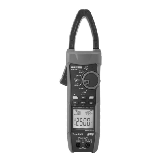
Electromagnetic compatibility: In an RF field of 1 V/m, total accuracy = specified accuracy + 5% of range; In an RF field of over 1 V/m, there is no specified specification. VII. External Structure 1: UT219PV structure (Figure 1) Figure 1 1) Clamp jaw... -
Page 8: Rotary Switch
UT219PV User Manual VIII. Rotary Switch (Figure 2) Figure 2 Position Description Power off DC current measurement V / V AC/DC voltage measurement VA/V+A DC power measurement/DC voltage + DC current measurement Flex current sensor measurement/AC current measurement (clamp jaws) /Ω/ /... -
Page 9: Button Functions
UT219PV User Manual IX. Button Functions (Figure 3) Figure 3 Short press: Press for 2 s Long press: Press for ≥2 s Button Description Short press: 1) DCV/ACV position: Short press to select DCV and ACV positions cyclically. Default position: DCV 2) VA/V+A position: Short press to select VA and V+A positions cyclically. -
Page 10: Lcd Display
UT219PV User Manual Short press: With Bluetooth off: Short press to save measurement data once in UT219PV. With Bluetooth on: Short press to start one-time recording via mobile phone. Long press: With Bluetooth off: Long press to save measurement data continuously in UT219PV. - Page 11 UT219PV User Manual Bluetooth Auto-save data Clearing storage data Recording data Max/Min/Average measurement Hazardous voltage AC measurement DC measurement Auto power off Data hold Auto data hold Displayed value (main display) Zero the residual reading of DC Low pass filter...
-
Page 12: Operating Instructions
UT219PV User Manual XI. Operating Instructions Please check the built-in batteries (AA 1.5V × 2) before use. If low battery occurs after the Clamp Meter is turned on, the symbol “ ” will be displayed on the LCD. To ensure measurement accuracy, please replace the batteries in time. - Page 13 UT219PV User Manual ● If residual reading occurs for DC current measurement, please press the ZERO button to clear the residual reading. ● “OL” will be displayed when measuring DC current of ≥1000 A. 2. AC/DC voltage measurement (Figure 6) Figure 6 1) Connect the red test lead to “V”...
- Page 14 UT219PV User Manual ACV-LPF Warning: ● Do not input voltage over 2500V DC or 1500V AC. It is possible to measure higher voltage, but it may cause damage to the Clamp Meter. ● For high voltage measurement, please pay special attention to avoid electric shock.
- Page 15 UT219PV User Manual 1) Connect the red test lead to “V” terminal and black to “COM”. 2) Set the rotary switch to “ ”, short press the SELECT button to switch to VA or V+A function, connect (in parallel) the test leads with the source or load to be measured, press and hold the trigger to open the clamp jaws, clamp the conductor to be measured, then release the trigger slowly to close the clamp jaws completely.
- Page 16 UT219PV User Manual 1) Set the rotary switch to “ ”. When the flex current sensor is connected, the Clamp Meter will automatically switch to corresponding measurement range, and “CS” and the symbol of corresponding range will be displayed. 2) Press and hold the trigger to open the clamp jaws, clamp the conductor to be measured, then release the trigger slowly to close the clamp jaws completely.
- Page 17 5 Hz~10 Hz: ≥10 A 10 Hz~100 Hz: ≥5 A 100 Hz~999.9Hz: ≥10 A ● The error specified by the flex current sensor is the intrinsic error of UT219PV. 5. Resistance measurement (Figure 10) Figure 10 1) Connect the red test lead to “V” terminal and black to “COM”.
- Page 18 UT219PV User Manual Warning: ● For continuity test at 999.9Ω, fast response cannot be achieved. For resistance ≤30Ω, continuous sound is generated and green backlight is lit up. For resistance ≥50Ω, no sound is made. ● Before measuring in-circuit resistance, please switch off all powers of the measured circuit and discharge all capacitors thoroughly.
- Page 19 UT219PV User Manual maximum range. ● To avoid damage to the Clamp Meter and personal injury, please switch off all powers of the measured circuit and discharge all capacitors thoroughly before measurement, especially the capacitor with high voltage. ● Please disconnect the test leads from the measured circuit after all measurement operations are completed.
- Page 20 UT219PV User Manual Warning: ● The input impedance is about 10 MΩ for DC mV. Measurement error can be produced when measuring circuit with high impedance. The circuit impedance is below 10 kΩ in most cases, thus the error (≤0.1%) is negligible.
-
Page 21: Other Functions
Bluetooth on fails to connect with the APP, the Bluetooth symbol on the LCD will blink. Open the “UNI-T Smart Measure” APP, search UT219PV, make connection, and then perform data communication, button control and other operations. The Bluetooth symbol on the LCD is displayed continuously with the connection established. -
Page 22: Technical Specifications
UT219PV User Manual XIII. Technical Specifications Accuracy: ± (a% of rdg. + b dgt.); guaranteed for 1 year Ambient temperature and humidity: 23℃±5℃; ≤80% RH Temperature coefficient: The temperature condition to ensure accuracy is 18°C~28°C. The fluctuation range of ambient temperature keeps within ±1°C. If the temperature is 18°C or >28°C, the additional error of temperature coefficient is “0.1 ×... - Page 23 UT219PV User Manual ACV: 1%~100% of range ACV-LPF: 10%~100% of range * Add an error for the AC crest factor of non-sine wave a) Add 3% for crest factor of 1~2 b) Add 5% for crest factor of 2~2.5 c) Add 7% for crest factor of 2.5~3...
- Page 24 UT219PV) * 30.00A: 1A = 100mV (AC); 300.0A: 1A = 10mV (AC); 3000A: 1A = 1mV (AC). * The specified accuracy at this measurement position is the intrinsic accuracy of UT219PV (eliminate the error of flex current sensor).
- Page 25 UT219PV User Manual 9.999kΩ 0.001kΩ 99.99kΩ 0.01kΩ * Precision range: 1~100% of range *For continuity test at 999.9Ω, fast response cannot be achieved. For resistance ≤30Ω, continuous sound is generated and green backlight is lit up. For resistance ≥50Ω, no sound is made.
-
Page 26: Bluetooth
For iOS 3. Use 3.1) Open the Bluetooth functions of both the Clamp Meter and mobile phone, tap the “UNI-T Smart Measure” APP icon on your phone desktop to open the software, then the software enters the navigation interface and searches nearby Bluetooth-enabled meters automatically. After that, select the corresponding meter and make connection. -
Page 27: Maintenance
UT219PV User Manual the operating instructions about these functions, please refer to the “UNI-T Smart Measure” User Manual (In the APP, tap the menu button, “Setting” button, and then “Help Guide” button for the User Manual). 4. Uninstallation Uninstall the software through the uninstallation function of mobile phone.
Need help?
Do you have a question about the UT219PV and is the answer not in the manual?
Questions and answers