Table of Contents
Advertisement
Quick Links
Installation, Operation and Maintenance Manual
Please read and save these instructions for future reference. Read carefully before attempting to assemble, install,
operate or maintain the product described. Protect yourself and others by observing all safety information. Failure
to comply with these instructions will result in voiding of the product warranty and may result in personal injury
and/or property damage.
General Safety Information
This instruction manual provides installation, operating,
maintenance, and parts information for the ERV
Controller.
WARING
Improper installation, adjustment, alterations, service
or maintenance can cause injury and property
damage, as well as possible voiding of factory
warranty. No person may install, operate, or maintain
the ERV Controller without first being fully trained
and qualified in the installation, operation and
maintenance, and carefully reading and understanding
the contents of this manual. If you have any
questions about these instructions, contact your local
representative.
Only qualified personnel
Personnel
should
have
a clear understanding of
these
instructions
and should
safety
precautions.
Improper
in electric shock, possible
contact with moving
parts,
hazards. for
more information, contact
professional
engineer before moving forward.
1. Follow all local electrical and safety
as well as
the
National
(NEC)
and
the
National
Agency
(NFPA),
the Canadian
Electrical
ULC-S650 if installing this
Canada.
2. Verify that the power source is compatible
with the equipment
should
install
this product.
be
aware of general
installation can
result
injury
due to coming
in
as well as other
potential
a licensed
codes,
Electrical
Code
Fire
Protection
where applicable.
Follow
Code (CEC) and
product
in
User and Service Manual
Technical Support
Call 1-800-789-8550
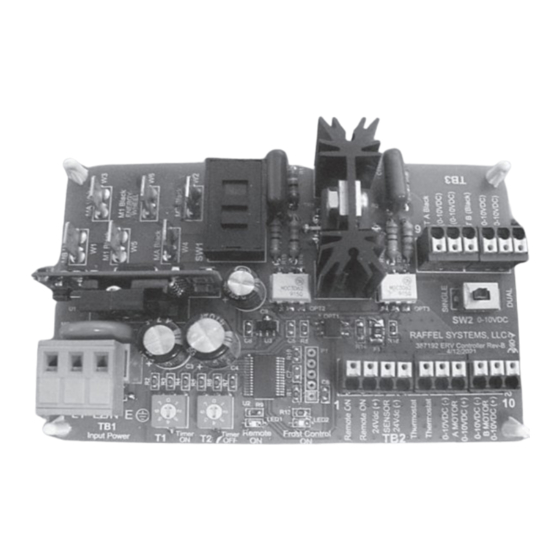
ERV Controller Features
• UL Compliance E479135.
• Simple Installation & Setup
• Wide Range 100-277Vac, 50/60 Hz Input Voltage.
• Solid State Motor Control.
• Remote ON/OFF Control Input.
• Green LED Indicator for Remote ON.
• 24Vdc @ 100mA available for Remote Sensor Power.
• Remote Thermostat Input for Frost Control.
• Adjustable ON/OFF Timers for Frost Control.
• Blue LED Indicator Frost Control.
• 0-10VDC Single or Dual Motor Speed Control Switch
SW2.
• Inlet/ Outlet Motor Swap Switch SW1. Swaps Inlet
and Exhaust Motors without re-wiring.
Document
486439
ERV Controller
ERV Controller
1
Advertisement
Table of Contents

Related Manuals for valent ERV Controller

Summary of Contents for valent ERV Controller
-
Page 1: General Safety Information
No person may install, operate, or maintain the ERV Controller without first being fully trained and qualified in the installation, operation and maintenance, and carefully reading and understanding the contents of this manual. -
Page 2: Table Of Contents
General Safety Information ..... . 1 ERV Controller Features ......1 Receiving, Handling, Storage . -
Page 3: Receiving, Handling, Storage
Receiving Control Components Upon receiving the product, check ensure all items Verify that all of following parts and hardware are accounted for by referencing the delivery receipt have been received prior to beginning installation. or packing list. Inspect each crate or carton for Contact your local representative or the... -
Page 4: Mounting And Wiring
Mounting & Wiring Hand/Off/Auto (HOA) Controller Mounting ERV Control PCB GPN: 387192 HOA Wiring ERV Controller... -
Page 5: Erv Specifications
UL E479135 Provide a close contact between TB2-1 and TB2-2 will Conditions of Acceptability active the ERV Controller. 1. ERV Controller must be mounted in a suitable end-use enclosure. Sensor Remote Power 2. Load motors rated 3/4HP shall be R/C (XDNW2) -
Page 6: Troubleshooting Guide
Remote ON ¦ No contact closure between Pins 1 & 2 ¦ Validate Motor Wiring of TB2 for Remote “ON” ¦ Validate Green LED on ERV Controller is illuminated “ON” ¦ Validate Motor wiring to W5 and W6 Energy Wheel Motor (1/4”) Spade Faston tabs on ERV... -
Page 7: Maintenance Log
Maintenance Log Date ___________________Time _____________ AM/PM Date ___________________Time _____________ AM/PM Notes: ___________________________________________ Notes: ___________________________________________ _________________________________________________ _________________________________________________ _________________________________________________ _________________________________________________ _________________________________________________ _________________________________________________ _________________________________________________ _________________________________________________ Date ___________________Time _____________ AM/PM Date ___________________Time _____________ AM/PM Notes: ___________________________________________ Notes: ___________________________________________ _________________________________________________ _________________________________________________ _________________________________________________ _________________________________________________ _________________________________________________ _________________________________________________ _________________________________________________ _________________________________________________ Date ___________________Time _____________ AM/PM... - Page 8 ERV Controller Manual Part number: 486439 Rev. 1 © 2023 Valent November 2023 Continuous product improvement is a policy of Valent; therefore, product functionality and specifications are subject to change without notice. For the most recent product information visit the product website.
Need help?
Do you have a question about the ERV Controller and is the answer not in the manual?
Questions and answers