Table of Contents

Related Manuals for Conductix-Wampfler Xpair Series


Summary of Contents for Conductix-Wampfler Xpair Series
- Page 1 Xpair Series Industrial Remote Controls Installation and User Technical Manual translated from the original version Jay électronique - Conductix-Wampfler Zac la Bâtie rue Champrond 38334 Saint Ismier France 355040A Doc. ref.: 355040A - EN...
-
Page 3: Table Of Contents
Table Service Information ....................6 Introduction ......................... 7 Product Identification at Delivery ................8 3.1. Unpacking Recommendations ......................8 3.2. Product Identification at Delivery ......................8 3.2.1. Receiver Output Interfaces ........................8 3.2.2. Receiver Visual Interface ........................8 3.2.3. Transmitter Visual Interface ........................8 Product Illustration ..................... 9 4.1. Transmitter ............................9 4.2. Receiver ............................ - Page 4 7.6. Operation in Tandem Mode ......................29 7.6.1. Startup in Tandem Mode ........................30 7.6.2. Pairing One Transmitter to Two Receivers.................... 30 7.6.3. Pairing Three Transmitters with Two Receivers ..................30 7.6.4. Pairing Two Transmitters and Two Receivers ..................31 7.6.5. Auto Release ............................31 7.6.6. Voluntary Release ..........................31 7.7. Stopping Products ..........................32 7.7.1. Stopping in Standard Mode ........................32 7.7.2.
- Page 5 13. Technical Specifications ..................63 13.1. Receiver ............................63 13.1.1. Dimensions ............................64 13.2. Transmitter ............................65 13.2.1. Dimensions ............................65 13.3. Radio ..............................66 13.4. Battery pack (EMEA) ........................66 14. Standards and environmental specification ............67 15. Safety parameters ..................... 67 16. Recycling and Waste Management ................. 68 17.
-
Page 6: Service Information
Service Information Thank you for choosing the Conductix Wampfler Xpair radio control system that was designed with a focus on being a simple affordable system that serves the main application in the overhead crane industry. If you have any questions regarding the installation or use of the radio control system, please contact our service department “Customer Service”: Monday-Friday Tel: +33 (0)4 76 41 44 00 Email: support.technique.jay@conductix.com - 6 - Xpair - 355040A... -
Page 7: Introduction
Introduction Our Conductix-Wampfler Xpair radio remote control systems are specifically designed to manage a wide range of industrial equipment and machinery, including overhead cranes, jib cranes, gantries, tower cranes, electric hoists, winches, monorails, conveyor belts, mining equipment, and other wireless handling equipment. Each set consists of one radio control transmitters and one radio control receiver. Here are some of the notable product specifications: Radio Link: To ensure safety, the data transmitted between the sender and receiver is protected by Hamming „ codes and encoded in a manner that prevents any potential threats from a third-party attacker. RF Power: To avoid interfering with nearby radio connections, the radio emission power between the two devices „ is regulated to prevent radio spectrum pollution. Radio Channel: The equipment is fitted with systems that analyze radio signal quality to safeguard against any „ disruptions caused by the environment. Radio Pairing: With two-way radio linking, you can pair two pieces of equipment and configure the settings for „ their use. Reliable Push Buttons: The push buttons on the transmitter are reliable and have been designed and tested „ to handle over 500,000 maneuvers. Low Consumption: The transmitter runs with a Lithium-ion technology battery pack. „ Protection: The protection class of the transmitter and receiver is IP65. „ Compliance – The transmitter and receiver comply with the agreed european safety standards and compliant „ with European Directive 2014/53/EU (RED). -
Page 8: Product Identification At Delivery
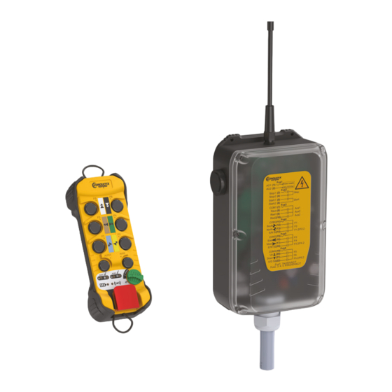
Product Identification at Delivery 3.1. Unpacking Recommendations When unpacking the product, do not throw away the supplied labels. 3.2. Product Identification at Delivery The set consists of the following items: One radio transmitter consisting of 6 function buttons, 2 auxiliary buttons, a rotary ON / OFF switch and a red „ safety stop button. A receiver box, equipped with a wire antenna, buzzer, internal lamp and output cable allowing connection to the „ interfaces to be controlled. A sheet of identification labels. „ Two Lithium-ion battery packs. „ 3.2.1. Receiver Output Interfaces 2 safety relays (safety stop) „... -
Page 9: Product Illustration
Product Illustration 4.1. Transmitter Front Face F5 double speed button Safety stop button F3 double speed button ON / OFF switch • position 0 = OFF • position I = ON • position START = Validation F1 double speed button Amber LEDs C and D AUX1 AUX2 Push button AUX1 Push button AUX2... -
Page 10: Receiver
4.2. Receiver Front Face RF Antenna Indicator LEDs Built-in Buzzer Transparent Cover with Wiring Label Cable Gland Numbered Wires Built-in White Lamp - 10 - Xpair - 355040A... -
Page 11: Product Operation Principle
Product Operation Principle 5.1. General This set includes a wireless command receiver and a transmitter that communicate with each other in both directions. The transmitter sends commands to the receiver, decodes them, and activates relay outputs based on the settings. 5.2. Main Applications Standard Crane: 3 motion 2 or 1 speed. „ Aux 1 and Aux 2 functions available with 3 wire hoists. Auxiliary Hoist: 4 motion 2 or 1 speed. „ Aux 1 function still available. Tandem Trolley: 5 motion 2 or 1 speed. „ Aux 2 functions still available. Tandem Crane: 6 motion 2 or 1 speed. „ Aux 2 function still available. Xpair - 355040A - 11 -... -
Page 12: Operating Modes
5.3. Operating Modes Xpair range products can operate in two distinct control modes. The Standard mode and Tandem mode. Standard: a transmitter and a receiver that communicate over a radio channel „ Tandem: with three versions „ • a transmitter and two receivers that communicate over a radio channel Tandem/Tandem „ • two tandem transmitters can control either or both receivers. Tandem/Dedicated „ • single transmitter that can control either or both recievers. Dedicated transmitters that only control cranes A and B individually. The tandem operating mode is accessible if the function is unlocked in the receiver parameters. This parameter can be configured using the JAYDialog software tool. - 12 - Xpair - 355040A... -
Page 13: Start Up And Use
Start up and Use 6.1. Receiver Electrical Connection Instructions IMPORTANT: IF THE TRANSCEIVER IS POWERED DIRECTLY FROM THE DISTRIBUTION NETWORK, THE “IT” TYPE ELECTRICAL DISTRIBUTION DIAGRAM CANNOT BE USED FOR THE TRANSCEIVER POWER SUPPLY A trained and authorized professional must carry out the electrical installation. To avoid any risk of electrocution, never open the receiver module's housing when powered on. -
Page 14: Rules Of Use And General Precautions
6.2. Rules of Use and General Precautions A radio-control system is considered as a control device and as a safety component used to stop a machine as specified by the EEC Machinery Directive. Its proper implementation must comply with resulting rules. The system allows the operator to focus their attention on their work by choosing the place of observation limited only by safety requirements (e.g.: not parking under a suspended load). -
Page 15: Factory Defaults
6.3. Factory Defaults A fixed radio channel is automatically assigned „ Radio power is set to automatic power regulation „ Standby is set to 4 minutes „ Buzzer is set to sound level 2, automatic pattern (the pattern depends on the channel) „ Without start-up protection sequence „ Passive stop delay is set to 1 second „ In automatic release mode and active sign-of-life mode „ Aux1 and Aux2 set to momentary control. „ Xpair - 355040A - 15 -... -
Page 16: Product Use
Product Use Getting Started Fault detected? List of faults Transmitter associated with receiver(s)? Primary or secondary pairing Configuration required? Operation for Controlling Equipment Settings Standard or Tandem Mode - 16 - Xpair - 355040A... - Page 17 7. Use of Products 7.1. Getting Started with Products 7.2. Pairing Primary Pairing (AUX1 + F1) Secondary Pairing (AUX1 + F2) 7.3. Transmitter UI 7.3.3. Default Signaling 7.4. Receiver Indicators, Relays, and Outputs 7.5. Operation in Standard Mode 7.6. Operation in Tandem Mode 7.7. Stopping Products 8.
-
Page 18: Getting Started With Products
7.1. Getting Started with Products 7.1.1. Powering On Power up the receiver, the amber Insert the battery pack into the Unlock the transmitter by lifting the power LED lights up. back of the transmitter. safety stop button. AUX1 AUX2 After three start-up attempts using the wrong code, the AUX1 AUX2 transmitter turns off. To restart, turn the AUX1 AUX2 ON / OFF switch to 0, then I. AUX1 AUX2 Start the transmitter by turning If LEDs A, B, C, and D flash at If the code is incorrect, the red the ON / OFF switch to I (ON) the same time, the transmitter is... -
Page 19: Power-On Self-Test (Default Off Button)
AUX1 AUX2 AUX1 AUX2 AUX1 AUX2 AUX1 AUX2 AUX1 AUX2 After successful initialization and if To start the radio link, turn the In the event of initialization failure „ products have been configured: or when a fault appears on the ON / OFF switch to START • The radio LED is continuously on transmitter, this is indicated by the Or to go to product configuration, „ • The battery LED indicates the various LEDs on the interface. -
Page 20: Pairing
7.2. Pairing During a pairing, the transmitter and receiver exchange application settings and the radio channel over which they will communicate. The procedure for a primary or secondary pairing is similar, only the mode selection (step 1) and corresponding visual indication differ. Pairing Type Access to Configuration Mode Visual Indication (via transmitter interface) Primary AUX1 + F1 Secondary AUX1 + F2 Products must be ready for configuration (if the transmitter and receiver are not powered on and unlocked, perform the steps in Chapter 7.1). 7.2.1. Primary 7.2.2. Secondary Pairing Pairing AUX1 AUX2 AUX1 AUX2 AUX1... - Page 21 Steps 2-8 are the same for primary or secondary pairing. Different step depending on pairing type AUX1 AUX2 AUX1 AUX2 Primary Pairing: simultaneously Release the ON / OFF switch to When a receiver is found, the lights press AUX1 + F1. start pairing: flash quickly to indicate it has been Secondary Pairing: simultaneously LEDs A, B, C, and D light up one selected and is ready for pairing. press AUX1 + F2. after the other to indicate that Then, press and hold the 2 a receiver search is in progress.
- Page 22 abandon AUX1 AUX2 AUX1 AUX2 AUX1 AUX2 AUX1 AUX2 AUX1 AUX2 AUX1 AUX2 Within 20 sec, press the F1 button LEDs A, B, C, and D indicate If the receiver does not receive the ID code within 20 sec following as many times as the number of the remaining time by turning switching the ON / OFF to START, receiver flashes. off successively every 5 sec in the receiver aborts the pairing. reverse alphabetical order: D after 5 sec, C after 10 sec, B after 15 sec, and A after 20 sec. AUX1 AUX2 AUX1 AUX2...
-
Page 23: Transmitter
7.3. Transmitter 7.3.1. Safety stop button The transmitter is equipped with a Safety stop button. This button must be unlocked before turning the ON / OFF switch to I, otherwise the transmitter cannot be used. To ensure that the Safety stop button works properly, the button must be tested once per year. 7.3.2. Transmitter LEDs The transmitter is equipped with the following visual indicators: Power indicator (“battery”) „ Radio indicator „ Two indicators, A and B, for the AUX 1 button „ Two indicators, C and D, for the AUX 2 button. „ 7.3.2.1. Battery Indicator (red LED) The red battery LED indicates the charge level. This level is visible after the transmitter is powered on (ON / OFF switch on I) or during operation of the radio control (radio transmission between the transmitter and the receiver). The table below shows the correspondence between LED status and the charge level of the transmitter: Transmitter Charge Status Red “Battery”... -
Page 24: Default Signaling
7.3.2.3. AUX Button Indicator Each AUX1 or AUX2 button can be assimilated, depending on its configuration: • to a 3-position or 2-position function switch • or a latching control • or a momentary control Button configuration changes from one type to another each time the corresponding AUX button is pressed and is indicated by a pair of two LEDs: • LEDs A and B for the AUX1 button • LEDs C and D for the AUX2 button. When the transmitter is powered on, LEDs A, B, C, and D light up briefly during the initialization phase (2 sec). If the button AUX1 is configured in tandem selector, the indicator position A / B correspond to the last position saved before start performed previously. For latching configuration of the button AUX1, the LED A blink previously start and light up if the relay Aux is closed. For indicator C / D the comportment is the same that previously, depending on the configuration of AUX2 button. Button configurations can be changed by setting, refer to Chapter 8.3 for details. 7.3.3. Default Signaling When a fault appears on the transmitter, it is signaled via the various LEDs on its interface. Transmitter LED Status Description The battery LED and radio LED flash alternately Safety stop button locked The battery LED and radio LED flash simultaneously Default buttons (F1 to F6, AUX1, AUX2) (remain pressed) -
Page 25: Receiver Indicators, Relays, And Outputs
7.4. Receiver Indicators, Relays, and Outputs 7.4.1. Receiver Visual Indicators The receiver has 3 internal status LEDs, these are used to indicate the following statuses: Orange power LED: indicates that the receiver is ON „ Green radio LED: indicates that the receiver is communicating with a transmitter „ Red diagnostic LED: indicates default statuses. „ The receiver also has a light that is visible through the transparent cover. This allows you to see different operating phase statuses of the receiver: Light Status Safety Relay Position Description Receiver is free Light is OFF Open (“Tandem” mode) Receiver is communicating with Light is ON Closed a transmitter Receiver is being used by one of Light flashes once periodically Open the transmitters in “... -
Page 26: Safety Relay
7.4.4. Safety Relay The receiver is equipped with two safety relays and one safety function relay. The two safety relays are active in operation as soon as the link is established between the transmitter and the receiver, as long as an active stop has not been received. 7.4.5. Function Relay Output Assignment The function safety relay is active as soon as a function button is active (buttons F1 to F6) . Function relay outputs are assigned to function buttons as shown below: Function (K13) Buttons Relay Relay Relay Relay Relay Relay Relay Relay Relay F1 - 1 ■ F1 - 2 ■ ■ F2 - 1 ■ F2 - 2 ■... -
Page 27: Output Interlock
7.4.6.2. AUX2 Function Setting Switch 1 Aux 2-1 Relay Behavior (K11) Aux 2-2 Relay Behavior (K12) Momentary control ON when AUX2 auxiliary button Reverse of relay Aux 2-1 (K11) is active Latching control Each time the AUX2 button is (C/0) pressed, the relay status changes Reverse of relay Aux 2-1 (K11) (OFF ↔ ON) 2 Position Selector Mode Pos 0: OFF Reverse of relay Aux 2-1 (K11) (C/D) Pos 1: ON 2 Position Selector Mode Pos 0: ON Pos 0: OFF (C/D/C + D) Pos 1: OFF Pos 1: ON Pos 2: ON Pos 2: ON 3 Position Selector Mode (C/D/0) Pos 0: ON... -
Page 28: Operation In Standard Mode
7.5. Operation in Standard Mode For a transmitter to start a receiver, the products must be paired first. Each product has its own ID code, and each knows the code of its contact. These ID codes allow identification with the recipient of the message. Products must be ready (if the transmitter and receiver are not powered on and unlocked, perform the steps in Chapter 7.1). AUX1 AUX2 AUX1 AUX2 AUX1 AUX2 AUX1 AUX2 Turn the ON / OFF switch to the I Release the ON / OFF switch. Use the remote control to operate your equipment. -
Page 29: Operation In Tandem Mode
7.6. Operation in Tandem Mode The tandem operating mode is accessible if the function is unlocked in the receiver parameters. This parameter can be configured using the JAYDialog software tool. This feature makes it possible to control two devices synchronously with a single transmitter and two receivers (one main and one secondary). The AUX1 auxiliary button on the transmitter is used to select the control type: Independent operation (standard mode one transmitter and only one of the two receivers) or operation of the two associated receivers at the same time: Tandem mode one transmitter (TxA) with two receivers (RxA and RxB) „ The AUX1 auxiliary button on the transmitter is used to select the operating modes: Dedicated mode (standard mode one transmitter and only one of the two TxA-RxA or TxA-RxB receivers) or tandem mode for control of the two associated receivers at the same time (TxA - RxA + RxB). Tandem/Dedicated mode 3 transmitters (TxA, TxB,TxC) and two receivers (RxA, RxB) „... -
Page 30: Startup In Tandem Mode
The AUX1 button can be configured and its configuration is indicated by the pair of LEDs A and B, refer to Chapter for details. 7.6.1. Startup in Tandem Mode In order to start in tandem mode, both receivers must be “free” that is, they are in safety mode and listening to the primary transmitter and neighboring transmitter. To start in Tandem mode, follow the three steps below: Switch on the products: follow the instructions described in Chapter 7.1. „ When starting in Tandem mode, check that the AUX1 button is set to selection A+B (LEDs A and B continuously „ ON). Otherwise press the AUX1 button as many times as necessary to reach this selection. It is possible to control one receiver at a time. In this case, the AUX1 button must be in position A or B before START. To start operating, turn the ON / OFF switch to START, then release it. „ When the AUX1 is set to selection A+B, the relay Aux1 is closed. When the AUX1 is set to selection A or B, it is possible to activate the relay Aux1 by pressing one of the function buttons (F1 to F6) in the first speed, then confirm by turning the ON / OFF switch to START and releasing it. In this case the relay Aux1 remains active for 30 seconds after the function button has been pressed. If one of the other function buttons is pressed on second step, the relay Aux1 is instantaneously released. 7.6.2. Pairing One Transmitter to Two Receivers For Tandem operation of one transmitter (Tx) with two receivers (RxA and RxB), follow the steps below: Switch on the Tx, RxA and RxB products. -
Page 31: Pairing Two Transmitters And Two Receivers
7.6.3. Pairing Three Transmitters with Two Receivers Switch on the Tx and Rx products. „ Perform primary pairing of TxA with RxA. Parameters of the RxA receiver are downloaded. „ Perform primary pairing of TxB with RxB. Parameters of the RxB receiver are downloaded. „ Perform primary pairing of TxC with RxA. „ Perform secondary pairing of TxC with RxB. „ The untimely loss of the radio link during operation in A + B selection will stop the steering. 7.6.4. Pairing Two Transmitters and Two Receivers For operation in Tandem mode with two transmitters (TxA and TxB) with two receivers (RxA and RxB) in the same area, follow the steps below: Switch on the TxA, RxA products. „ Perform the main pairing of the TxA transmitter with the RxA receiver. Parameters of the RxA receiver are „... -
Page 32: Voluntary Release
7.6.6. Voluntary Release Depending on the settings it is possible to manually release the receivers, to: • release them for another use, or • keep them, but make them unavailable to the neighboring transmitter. A receiver can be released only by the last transmitter that used it. A receiver can be released before the transmitter is turned off (Safety stop button or turning the ON / OFF switch to OFF): Hold the AUX1 button for 4 seconds: the transmitter sends release frames to the receiver. The receiver „ acknowledges the release by switching off the respective Aux1 relay. After 4 seconds, the A, B, C, and D LEDs turn off. „ In some cases, release may not be feasible (interference, receiver too far away), in this case the receiver remains busy. Release is still possible by cutting the power supply to the receiver. Caution, a receiver that has not been released can only be restarted by the last transmitter that used it. -
Page 33: Product Settings
Product Settings 8.1. Access to Settings All of the following settings must be configured after the primary pairing between the transmitter and the receiver. This operation must be done with the receiver powered on so that it can save the new settings. 8.1.1. Setting Entry In Setting mode, the behavior of the battery and radio LEDs is as follows: Transmitter Indicator Status Description A setting entry is active. The number of flashes of the battery LED/radio LED The red battery LED and the green radio LED pair indicates the setting being modified as long as the flash according to the Setting mode ON / OFF switch is maintained in the START position. After releasing the switch, the battery and radio LEDs are off. -
Page 34: Auxiliary Button Configuration (Aux1 + Aux2)
8.3. Auxiliary Button Configuration (AUX1 + AUX2) The transmitter’s auxiliary pushbuttons can be configured in several ways according to needs: They can be associated with the Relay’s function relays Aux 1, Aux 2-1, and Aux 2-2. The AUX1 and AUX2 can be configured as follows: Pushbutton with momentary control (AUX1 and AUX2) „ Latching button (AUX1 and AUX2) „ Bridge selector button (Tandem AUX1) „ Relay selector button (AUX2). „ LEDs A and B indicate the current setting of the AUX1 button and LEDs C and D indicate the setting of the AUX2 button. The settings and corresponding light signals are listed in the table below: AUX1 button LED A LED B Momentary control (Aux 1 relay) continuous Latching control (Aux 1 relay) flashing A/B selection A and B flashing alternately A/B/A + B selection ON sequence: A, B, A + B Continuous selection A A alone, then B flashing stealthily Tandem mode Continuous selection B... - Page 35 AUX1 AUX2 AUX1 AUX2 AUX1 AUX2 AUX1 AUX2 AUX1 AUX2 AUX2 AUX1 AUX2 AUX1 AUX2 Turn ON / OFF switch to the I Release the ON / OFF switch Each time one of the AUX1 and all other buttons to start the (ON) position. Ensure the LEDs or AUX2 buttons is pressed, configuration. the lighting sequence of the A through D turn on and then off. 2 corresponding LEDs indicates Then press and hold the AUX1 the operating mode.
-
Page 36: Sleep Mode Configuration (F1 + F3)
8.4. Sleep Mode Configuration (F1 + F3) The transmitter is put into standby mode if no function button has been pressed in the set time. The sleep time can be set from 1 to 99 minutes maximum and from 10 to 59 seconds. The factory setting is 5 minutes. Products must be ready for configuration (perform steps in Chapter 7.1). AUX1 AUX2 AUX1 AUX2 AUX1 AUX2 AUX1 AUX2 AUX1 AUX2 AUX1 AUX2 Turn ON / OFF switch to the I Release the ON / OFF switch and To disable sleep mode, press the (ON) position. Ensure the LEDs AUX1 button: all other buttons: A through D turn on and then off. -
Page 37: Radio Power Configuration (F1 + F4)
8.5. Radio Power Configuration (F1 + F4) By default, the transmitter and receiver modules analyze the quality of the signal received from both sides and adapt the power level according to the environment. However, it is possible to set the radio power of the products. Power is factory set to Auto. There are 2 power modes: Auto LED D is continuously on and A, B, and C are off „ Fixed Manual; LED D is off and LED B indicates the value of the power set in the range 1 (min) to 4 (max) „ by successive flashing. Products must be ready for configuration (perform steps in Chapter 7.1). AUX1 AUX2 AUX1 AUX2 AUX2 AUX1 AUX2 AUX1 AUX2 AUX1 AUX2 Turn ON / OFF switch to the I Release the ON / OFF switch Press the AUX2 button to enable (ON) position. Ensure the LEDs and all other buttons to start the... -
Page 38: Start Protection And Configuration (Sequence With F1 - F6)
8.6. Start protection and configuration (sequence with F1 – This setting protects the products with a code and prevents unauthorized use of the transmitter. The code represents a sequence obtained by a combination of the six F1 to F6 buttons. The button sequence can be variable in length, from a minimum of 2 buttons to a maximum of 6 buttons. It is possible to use the same button several times. Protection is not enabled in the factory setting. Products must be ready for configuration (if the transmitter and receiver are not powered on and unlocked, perform the steps in Chapter 7.1). Note: - If a protection sequence is activated, it is not possible to do a secondary pairing. It is required to disable protection first with primary transmitter. - Page 39 AUX1 AUX2 AUX1 AUX2 AUX1 AUX2 AUX1 AUX2 AUX1 AUX2 AUX1 AUX2 Enter the code by pressing At the end of the sequence, Release the ON / OFF switch: confirm by turning the ON / OFF successively on the buttons LEDs A and B are continuously on (chosen sequence): LED A turns switch to START. to indicate that the code must be off then on after each pressing of Note: If the sequence entered is re-entered to confirm it. the F1 to F6 button. incorrect (length), you are returned Do not press any button to clear to Step 2. the previous code and disable it at power up.
- Page 40 When the sequence is incorrect, the red LED lights up for 2 sec and LEDs A, B, C and D flash. AUX1 AUX2 AUX1 AUX2 If the second code is different from the first code, resume Step 2. AUX1 AUX2 AUX1 AUX2 If the two codes entered are the End of transmission: same, the sequence is transmitted •...
-
Page 41: Rf Channel Configuration (F1 + F2)
8.7. RF Channel Configuration (F1 + F2) 8.7.1. Fixed Radio Channel Setting The radio channel of the transmitter and receiver can be set from 1-92 and the number of flashes of LEDs A and B indicate the radio channel number. Products must be ready for configuration (if the transmitter and receiver are not powered on and unlocked, perform the steps in Chapter 7.1). AUX1 AUX2 AUX1 AUX2 AUX1 AUX2 AUX2 AUX1 AUX2 AUX1 AUX2 Turn ON / OFF switch to the I Release the ON / OFF switch Set the channel: (ON) position. Ensure the LEDs... -
Page 42: Channel Auto Selection Setting (Aux2)
8.7.2. Channel Auto Selection Setting (Aux2) The channel auto selection function scans the frequency band used in the area where products are installed and identifies channels not used in this area by other equipment. For best results, it is necessary to start the function and move the transmitter close to other transmitters operating in the application area. Products must be ready for configuration (if the transmitter and receiver are not powered on and unlocked, perform the steps in Chapter 7.1). AUX1 AUX2 AUX1 AUX2 AUX2 AUX1 AUX2 AUX1 AUX2 AUX1 AUX2 Turn ON / OFF switch to the I Press the AUX2 button to start the LED A indicates the tens and LED (ON) position. Ensure the LEDs B the ones of the current channel. -
Page 43: Free Channel Startup Setting (F5)
8.7.3. Free Channel Startup Setting (F5) When the receiver is not communicating with the associated transmitter, it alternately listens to its current channel and the other channels of the frequency band. It then determines the channel that seems to be the best. Free channel startup informs the transmitter at start-up to use the best available channel selected by the receiver. Products must be ready for configuration (if the transmitter and receiver are not powered on and unlocked, perform the steps in Chapter 7.1). AUX1 AUX2 AUX1 AUX2 AUX1 AUX2 AUX2 AUX1 AUX2 AUX1 AUX2 Turn ON / OFF switch to the I Release the ON / OFF switch Press the F5 button to enable (ON) position. Ensure the LEDs and all other buttons to start the... -
Page 44: Channel Agility Setting (F6)
8.7.4. Channel Agility Setting (F6) The channel agility setting changes the channel automatically when it has been identified as busy, following a proprietary algorithm. Changing the radio channel is initiated by the receiver which transmits this information to the transmitter. Products must be ready for configuration (if the transmitter and receiver are not powered on and unlocked, perform the steps in Chapter 7.1). AUX1 AUX2 AUX1 AUX2 AUX1 AUX2 AUX2 AUX1 AUX2 AUX1 AUX2 Turn ON / OFF switch to the I Release the ON / OFF switch Press the F6 button to enable the (ON) position. Ensure the LEDs and all other buttons to start the... -
Page 45: Receiver Horn Configuration (Aux2 + F1)
8.8. Receiver Buzzer Configuration (AUX2 + F1) This setting allows you to define different modes of operation of the buzzer signal according to needs and LEDs A,B,C, and D indicate the pattern and the sound level: Pattern Selection: Configurable from 1 to 99 ↔ LED A indicates tens and LED B indicates the ones. „ Automatic Pattern: This depends on the radio channel used ↔ indicated by LED D (automatic when the LED is „ on and manual when the LED is off). Sound Level: Configurable from 1 to 2 ↔ indicated by LED C (high if the LED is on and low if the LED is off). „ By default, products are delivered in automatic pattern mode and level 2. The buzzer is active according to a pattern depending on the setting or radio channel (automatic) of the receiver. Products must be ready for configuration (perform steps in Chapter 7.1). AUX1 AUX2 AUX1 AUX2 AUX2 AUX1 AUX2 AUX1 AUX2 AUX1 AUX2 Turn ON / OFF switch to the I Release the ON / OFF button To change the pattern: (ON) position. Ensure the LEDs... - Page 46 AUX1 AUX2 AUX1 AUX2 AUX1 AUX2 AUX1 AUX2 AUX1 AUX2 AUX1 AUX2 Select the desired sound level The AUX2 button enables Confirm the value by turning using the AUX1 button. automatic mode. the ON / OFF switch to START. During transmission: • Battery and radio LEDs flash alternately • Receiver light turns on. AUX1 AUX2 AUX1 AUX2...
-
Page 47: Passive Stop Configuration (Aux1 + Aux2 + F1 + F2)
8.9. Passive stop Configuration (AUX1 + AUX2 + F1 + F2) In case of radio interference or a too far distance between the equipment and the transmitter, the radio communication may be interrupted. In this case, the receiver switches to the safety position. A start-up procedure will need to be performed again to reactivate the receiver safety relays. You can configure four passive stop values from the transmitter and the setting value is indicated by LED B: 0.3 sec (1 flash), 0.5 sec (2 flashes), 1 sec (3 flashes) and 1.5 sec (4 flashes). The passive time must be properly chosen according to the risk analysis of the equipment to be controlled: If too short, unwanted stops may occur frequently „ If too long, the movement may continue for too long and can create dangerous situations. „ Products must be ready for configuration (if the transmitter and receiver are not powered on and unlocked, perform the steps in Chapter 7.1). AUX1 AUX2 AUX1 AUX2 AUX1 AUX2 AUX2 AUX1 AUX2 AUX1 AUX2 1.5s Turn ON / OFF switch to the I Release the ON / OFF switch The passive stop delay is factory-... - Page 48 To abort abandon AUX1 AUX2 AUX1 AUX2 AUX1 AUX2 AUX1 AUX2 AUX1 AUX2 AUX1 AUX2 Confirm the value by turning the End of transmission: It is possible to abort by turning the ON / OFF switch to START. ON / OFF switch from I to 0. • Receiver light turns off During transmission: • Transmitter shuts down and •...
-
Page 49: Info & Reset Menu (Aux1 + F4)
8.10. Info & Reset Menu (AUX1 + F4) This menu allows you to restore the factory defaults and check the transmitter and receiver software versions. The reset has the following action: To delete possible secondary receivers controlled by the transmitter (Tandem) „ To delete all transmitters paired to the receiver except the main receiver used „ To restore all factory defaults (refer to Chapter 6.3). „ After a reset, the factory defaults are restored and only the transmitter used for the reset is able to communicate with the "reseted" receiver and consequently to drive the equipment. AUX1 AUX2 AUX1 AUX2 AUX1 AUX2 AUX1 AUX2 AUX1 AUX2 SOFTWARE SOFTWARE AUX1 AUX2 AUX1 AUX2 AUX1 AUX2 Turn ON / OFF switch to the I Release the ON / OFF switch and... - Page 50 To abort Rest End abandon AUX1 AUX2 AUX1 AUX2 AUX1 AUX2 AUX1 AUX2 To abort the reset, turn the At the reset end: ON / OFF switch from I to 0. • Receiver white lamp turns off • Transmitter shuts down and restarts. Note: The reset factory is possible if the receiver is power on.If an error occur during the reset factory demand, battery led is on and led A blink. - 50 - Xpair - 355040A...
-
Page 51: Specific Tandem Mode Settings
Specific Tandem Mode Settings 9.1. Receiver Swapping A ↔ B (AUX1 + F5) This feature swaps the selection indicator of the AUX1 button. This feature is used when paired in a tandem because each transmitter automatically puts the primary paired receiver as A and the secondary paired receiver as B. Use this to switch naming on any transmitters that do not match site naming for crane A and B. Swapping configuration is indicated by LEDs A and B: • The selection indicators of receivers A and B are not swapped if LED A is on and LED B is off • The selection indicators of receivers A and B are swapped if LED A is off and LED B is on. Products must be ready for configuration (perform steps in Chapter 7.1). AUX1 AUX2 AUX1 AUX2 AUX2 AUX1 AUX2 AUX1 AUX2 x8 x4 AUX1 AUX2 Turn ON / OFF switch to the I... - Page 52 By default, after configuring an AUX1 function button and after pairing, swapping is disabled. AUX1 AUX2 AUX1 AUX2 AUX1 AUX2 AUX1 AUX2 Confirm the value by turning End of transmission: the ON / OFF to START. • Receiver light turns off During transmission: • Transmitter shuts down • Battery and radio LEDs and restarts. flash alternately • Receiver light turns on. - 52 - Xpair - 355040A...
-
Page 53: Release Function (Ungroup) (Aux1 + F3)
9.2. Release Function (Ungroup) (AUX1 + F3) This setting allows you to configure the release of one or more receivers that work with the transmitter. If automatic release mode is enabled, when the transmitter stops operating, the paired receiver(s) will be released and another transmitter can connect later. In the voluntary release mode, the operator must voluntarily release or not the receivers. Products are configured by default in automatic release mode. Release mode is indicated by the pair of A and B LEDs: • For automatic release, LED A is on and LED B is off • For voluntary manual release, LED A is off and LED B is on. Products must be ready for configuration (perform steps in Chapter 7.1). Note: When you change this parameter, it is recommended to do the same change on both receivers. So this procedure needs to be done with the primary Tx of each Rx. - Page 54 AUX1 AUX2 AUX1 AUX2 AUX1 AUX2 AUX1 AUX2 Confirm the value by turning End of transmission: the ON / OFF switch to START. • Receiver light turns off During transmission: • Transmitter shuts down • Battery and radio LEDs flash and restarts. alternately • Receiver light turns on. - 54 - Xpair - 355040A...
-
Page 55: Sign Of Life Between Receivers (F1 + F5)
9.3. Sign of Life Between Receivers (F1 + F5) In Tandem mode a sign of life is exchanged between the two receivers. This function is only valid when the transmitter controls both receivers (A + B). The sign of life determines if one of the receivers has released its safety relays or if radio communication between the two is broken. Products are configured at the factory in active life sign mode. Configuration of the sign of life mode is indicated by the pair of A and B LEDs: • Sign of life is enabled if LED A is on and LED B is off • Sign of life is disabled if LED A is off and LED B is on. If the sign of life disappears and one of the receivers has gone to safety, the second receiver will go to safety (this condition is only true, if the communication between receivers is available). If the sign of life disappears but the two receivers are still in operation (safety relay active), only the function output relay commands are disabled. The passive stop delay between 2 receivers (no communication between the receivers) is 900 ms. Products must be ready for configuration (if the transmitter and receiver are not powered on and unlocked, perform the steps in Chapter 7.1). AUX1 AUX2 AUX1 AUX2 AUX2 AUX1 AUX2 AUX1 AUX2 AUX1... - Page 56 AUX1 AUX2 AUX1 AUX2 AUX1 AUX2 AUX1 AUX2 Confirm the selected status by End of transmission: turning the ON / OFF switch to • Receiver light turns off START. During transmission: • Transmitter shuts down • Battery and radio LEDs and restarts. flash alternately • Receiver light turns on. - 56 - Xpair - 355040A...
-
Page 57: Installation Instructions
10. Installation Instructions 10.1. Transmitter Different button functions are identified by self-adhesive labels to be stuck on the transmitter box in the space provided for this purpose each button. Labels are delivered in sheets to be used according to the application. 10.2. Radio Receiver Position The receiver should be mounted in a protected place from shock and weather. The antenna should be as far away as possible from the power cables (power supply, motor, drive, etc.) but remain in an area favorable to radio reception. It must be located within sight of the operator handling the equipment. There should be no metallic masses near it. The antenna will be located high above the operator handling the transmitter. There should be no metal between „ the operator and the antenna. The antenna is directed towards the working areas of the transmitter (downwards in the case of a hoist). „ The correct orientation of the antenna is shown in the figure below: „ Xpair - 355040A - 57 -... -
Page 58: Mounting The Receiver
If the installation of the receiver does not allow the operator to see the antenna, it is advisable to offset the receiver antennas under the beams, and point them vertically towards the radio control area, as shown below: If several devices are equipped with radio controls, working in the same vicinity (e.g., in a factory), each transmitter must carry clear information that tells the operator which equipment it controls. Similarly, the operator must be able to identify the controls corresponding to the directions of movement of the equipment being steered. 10.3. Mounting the Receiver See Retrieve mechanical plan for attaching the housing. 9.02 in 229 mm 3.54 in 90 mm 10.4. Antennas 10.4.1. Antenna Type The receiver housing is equipped with a non-detachable antenna. However, it is possible to install a remote antenna. In this case, a BNC plug-in antenna kit must be purchased and installed (refer to Chapter 19.2 Accessories). - 58 - Xpair - 355040A... -
Page 59: Connection
10.5. Connection The receiver is equipped with an output cable for connecting the power supply and relay outputs. Below, the correspondence of the strand outputs and their assignments. Function Relay Fuse Marker Diagram Terminal Number Power input 48-230Vac FUS1 AC-1 Power input 48-230Vac AC-2 Safety relay output 1 FUS2 Safety relay output 2 Function ON output relay ON relay output AUX and selection FUS3 COM1 relay common Function relay output Aux 1 Function relay output Aux 1 Aux 2-1 Function relay output Aux 2 Aux 2-2 Common 2 FUS4 COM2 Function relay output F1 F1.1 Function relay output F2 F2.1 Function relay output F1/F2... -
Page 60: Connecting The Safety Relays
10.6. Connecting the safety relays The safety relays K14 and K16 are used to cut the main power supply source via 2 external contactors. The 2 safety relays RS1 and RS2 are activated when the radio link is established between the transmitter and receiver, and are automatically maintained until an active or passive stop (safety button pressed, radio link lost, battery discharged, "standby" function activated, etc.). The function safety relay K15 is used to cut the equipment controls shared line. It is active only if one of the function relays is active. Below is an example of the output wiring: Contactors C1 and C2 are guided contacts, to be integrated in the system safety chain * using overvoltage limiter circuits extends the service life of the relay contacts (e.g.: RC circuits in AC, diode + zener in DC, etc.) Using an external contactor requires evaluating the performance that the system as a whole can achieve. The function relays K1, K2, K3, K4, K5, K6, K7, K8, K9, K10, K11, K12, K13 are not part of the safety function. Only the safety relays K14, K15 and K16 are monitored. - 60 - Xpair - 355040A... -
Page 61: Maintenance
11. Maintenance BEFORE PERFORMING ANY MAINTENANCE, TURN OFF THE POWER TO THE PRODUCT 11.1. Receiver Maintenance The housing can only be disassembled by trained personnel in a “controlled” environment. Parts can only be replaced with identical spare parts. Check the connection of the antenna; it must be clean and unoxidized. „ Check the quality of power supply and control output wiring. „ Correct operation of shutdown circuits, active. „ Condition of cover gasket, tightness of fastening screws. „ Use only non-aggressive soap-based cleaners. „ 11.2. Transmitter Maintenance The transmitter housing must not be opened. Regularly check the condition of the transmitter, paying particular attention in the battery compartment. „... -
Page 62: Warranty
12. Warranty All our devices are guaranteed for two years from the day of shipment. Repairs, modifications or the replacement of a device during the warranty period shall not extend the warranty period. Restriction: The warranty does not cover defects resulting from: Transport „ Incorrect operation or failure to follow the connection diagrams during start up „ Lack of monitoring or maintenance, use not in accordance with the specifications in the technical manual and, „ in general, storage, operating or environmental conditions (atmospheric, chemical, electrical, mechanical or other influences) which are not suitable or not foreseen at the time of order The warranty cannot be exercised if modifications, dismantling or additions have been made by the customer without the written consent of our Company. The responsibility of Conductix-Wampfler during the period of warranty is limited to any material or construction defect; this includes the repair in its workshops or the free replacement of parts recognized as defective according the expertise of its “technical services”. Conductix-Wampfler cannot give right to any compensation for damages. In the event of a dispute concerning supply or payment, THE COMMERCIAL COURT OF GRENOBLE is the only competent authority, even in the event of Appeal or of plurality of defendants. - 62 - Xpair - 355040A... -
Page 63: Technical Specifications
13. Technical Specifications 13.1. Receiver Mechanical Specifications and Environmental Resistance Housing Material PA66 GF 30 (PC cover) Housing color Black background and translucent/transparent cover Protection Index IP65 (Indoor use only) Mass 1.4kg (including cable) Overall Dimensions 12.20 (without antenna, with PES) x 5.90 (with buzzer) x 3.14 in 310 (without antenna, with PES) x 150 (with buzzer) x 80 mm Fastening 4x screws M3 – 229 x 90 mm Possibility to add magnets with or without silent blocks Operating Temperature -20°C to +55°C Storage Temperature -20°C to +70°C Connection 22-strands cable, section 0.75mm², AWG 18... -
Page 64: Dimensions
Electrical Specifications Power Supply Supply voltage (steady state) 48Vac to 230Vac ± 10% - 50/60Hz Protection Fuse 0.5A Consumption <15W Pollution degree Overvoltage category Safety relay outputs Number of outputs (2 relays in series) Contacts AgNi + Au Contact Type Guided contact relays Break Capacity 250Vac @ 5A max (at max operating temperature) 12Vdc @ 50mA min Max Power at cos ø = 1 2000VA Switching Lifespan at 230VAC, 6A, cos ø... -
Page 65: Transmitter
13.2. Transmitter Mechanical Specifications and Environmental Resistance Housing Material PA66 GF 30 Housing color Yellow Protection Index IP65 Mass 300g max Overall Dimensions 7.09 x 2.76 x 1.77 in 180 x 70 x 45 mm Operating Temperature -20°C to +50°C Storage Temperature -30°C to +70°C Transport 2 strap anchor points... -
Page 66: Radio
13.3. Radio Radioelectrical Specifications (US) Transmission Frequency 433,1 - 434,675MHz Number of Channels Space Between Channels 25kHz Receiver Sensitivity -100dBm Transmission Power 1mW Modulation FSK Frame Hamming 4 distance with encryption against external attacks Medium Range* 54.7-109.4 yd / 50-100 m in industrial setting* 437.6 yd in / 400 m in open space Antenna Output Impedance 50Ohms Response Time at Startup 500ms Command Response Time 300ms * The range varies according to the environmental conditions of the transmitter and receiving antenna (frames, metal walls, etc.). -
Page 67: Standards And Environmental Specification
14. Standards and environmental specification According to the standard: Safety requirements for electrical equipment for measurement, control, and laboratory use; • IEC 61010-1:2010/AMD1 :2016 Degrees of protection provided by enclosures (IP code): • IEC 60529:1989/A1:1999 Altitude of the site of installation does not exceed 2000 m. The relative humidity of the air does not exceed 50 % at a maximum temperature of +40°C. Higher relative humidities may be permitted at lower temperatures, e.g. 90 % at + 20°C. 15. Safety parameter The tests were performed in accordance with the test principles as per standards EN ISO 13849-1 and ENISO 13849-2. The detailed reports are kept in the test laboratories. Operating and error simulation tests were performed, and the source code and documents were examined. Product Description Results Transmitter Safety stop MTTF Category Performance level... -
Page 68: Recycling And Waste Management
16. Recycling and Waste Management When this device is worn, it should not be disposed of in any kind of dumping ground. It can be taken to the specific collection centers, differentiated by local administrations, or to the distributors who take care of them. The sorting of electronic waste avoids possible negative consequences on the environment, derived from an inappropriate elimination and allows the processing and recycling of its materials, which favors important savings in terms of energy and resources. 17. Manufacturer Information Manufacturer and Factory: Jay électronique ZAC la Bâtie, rue Champrond F38334 SAINT ISMIER Cedex Tel: + 33 (0)4 76 41 44 00 ww.jay-electronique.com 18. Compliance Statement Product conformity statements are available at www.jay-electronique.com - 68 - Xpair - 355040A... -
Page 69: Appendix
19. Appendix 19.1. Radio Frequency Table channel 1 433.100MHz channel 32 433.875MHz channel 63 434.650MHz channel 2 433.125MHz channel 33 433.900MHz channel 64 434.675MHz channel 3 433.150MHz channel 34 433.925MHz channel 4 433.175MHz channel 35 433.950MHz channel 5 433.200MHz channel 36 433.975MHz channel 6 433.225MHz channel 37 434.000MHz channel 7 433.250MHz channel 38 434.025MHz channel 8 433.275MHz channel 39 434.050MHz channel 9 433.300MHz channel 40 434.075MHz channel 10 433.325MHz channel 41 434.100MHz channel 11 433.350MHz channel 42 434.125MHz channel 12 433.375MHz channel 43 434.150MHz channel 13 433.400MHz channel 44 434.175MHz channel 14 433.425MHz channel 45 434.200MHz channel 15 433.450MHz channel 46 434.225MHz channel 16 433.475MHz channel 47 434.250MHz channel 17 433.500MHz channel 48 434.275MHz channel 18 433.525MHz... -
Page 70: External Antenna Option
19.2.2. External antenna option The antenna of the receiver product is simple wire in standard version. It is possible to change this antenna by listed antennas below with an adaptor in option: Antenna reference: • VUA001A Type : right, 1/4 wave, BNC connection Approximate length: 190mm Antenna reference: • VUA002A Type: right, 1/2 wave, BNC connection Approximate length: 335mm Antenna reference: • VUA100AH (with 0.5m cable) • VUA102AH (with 2m cable) • VUA105AH (with 5m cable) • VUA110AH (with 10m cable) Type: remote, pass-through, insulated, 1/2 wave, BNC connection Approximate length: 320mm Drilling required: 15mm Antenna reference: • VUA103AM (with 3m cable) •... - Page 72 355040A ZAC la Bâtie, rue Champrond F38334 SAINT ISMIER Cedex Tel: +33 (0)4 76 41 44 00 www.conductix.com/en...
Need help?
Do you have a question about the Xpair Series and is the answer not in the manual?
Questions and answers