
Related Manuals for Amazone AD-P 303 Special


Summary of Contents for Amazone AD-P 303 Special
- Page 1 Operating Manual Top-mounted seed drills AD-P 303 Special AD-P 353 Special AD-P 403 Special Please read this operating manual before first putting in- to operation. MG3382 BAH0018-5 09.14 Keep it in a safe place for fu- ture use.
- Page 2 Reading the instruction manual and to adhere to it should not appear to be inconvenient and superfluous as it is not enough to hear from others and to realise that a machine is good, to buy it and to believe that now everything would work by itself.
- Page 3 + 49 (0) 5405 501-234 E-mail: amazone@amazone.de Spare part orders Spare parts lists are freely accessible in the spare parts portal at www.amazone.de. Please send orders to your AMAZONE specialist retailer. Formalities of the operating manual Document number: MG3382 Compilation date: 09.14 ...
- Page 4 Send us your suggestions by fax. AMAZONEN-WERKE H. DREYER GmbH & Co. KG Postfach 51 D-49202 Hasbergen Tel.: + 49 (0) 5405 501-0 Fax: + 49 (0) 5405 501-234 E-mail: amazone@amazone.de AD-P 03 Special BAH0018-5 09.14...
-
Page 5: Table Of Contents
Table of Contents User Information ..................10 Purpose of the document ....................10 Locations in the operating manual ..................10 Diagrams used ........................10 General safety instructions ..............11 Obligations and liability ....................... 11 Representation of safety symbols ..................13 Organisational measures .................... - Page 6 Table of Contents 5.4.1 Digital fill level monitoring (optional) .................. 57 Dosing ..........................58 5.5.1 Dosing rollers ........................59 5.5.2 Overview of dosing rollers ....................60 5.5.3 Seed/dosing rollers table ....................61 5.5.4 Seed rate adjustment at Vario gearbox ................62 5.5.5 Seed rate remote control, hydraulic on the Vario gearbox (optional) ........
- Page 7 Table of Contents 7.2.2 Connecting the pressure gauge ..................111 Uncoupling the top-mounted seed drill from the cultivator ..........112 Settings ....................116 Setting the level sensor..................... 116 Inserting the dosing roller into the dosing unit ..............118 Steps, transportation and operational position ..............120 Filling the hopper ......................
- Page 8 12.5.4 Handling the tapered clamping bushes for V-belt pulleys ..........187 12.6 Screw tightening torques ....................188 Hydraulic system diagrams ..............189 13.1 Hydraulic plan for AD-P 303 Special / AD-P 403 Special ..........189 AD-P 03 Special BAH0018-5 09.14...
- Page 9 Table of Contents AD-P 03 Special BAH0018-5 09.14...
-
Page 10: User Information
User Information User Information The User Information section provides information on how to use the operating manual. Purpose of the document This operating manual • Describes the operation and maintenance of the machine. • Provides important information on safe and efficient handling of the machine. -
Page 11: General Safety Instructions
General safety instructions General safety instructions This section contains important information on safe operation of the machine. Obligations and liability Comply with the instructions in the operating manual Knowledge of the basic safety information and safety regulations is a basic requirement for safe handling and fault-free machine operation. Obligations of the operator The operator is obliged only to let those people work with/on the ma- chine who... - Page 12 General safety instructions Risks in handling the machine The machine has been constructed to the state-of-the art and the recognised rules of safety. However, there may be risks and re- strictions which occur when operating the machine • For the health and safety of the user or third persons, •...
-
Page 13: Representation Of Safety Symbols
General safety instructions Representation of safety symbols Safety instructions are indicated by the triangular safety symbol and the highlighted signal word. The signal word (DANGER, WARNING, CAUTION) describes the gravity of the risk and has the following sig- nificance: DANGER Indicates an immediate high risk which will result in death or serious physical injury (loss of body parts or long term dam- age) if not avoided. -
Page 14: Organisational Measures
General safety instructions Organisational measures The operator must provide the necessary personal protective equip- ment, such as: • Safety glasses • Protective shoes • Protective suit • Skin protection, etc. The operating manual • must always be kept at the place at which the machine is oper- ated. -
Page 15: Training Of Personnel
General safety instructions Training of personnel Only those people who have been trained and instructed may work with/on the machine. The operator must clearly specify the responsi- bilities of the people charged with operation, maintenance and repair work. People being trained may only work with/on the machine under the supervision of an experienced person. -
Page 16: Safety Measures In Normal Operation
General safety instructions Safety measures in normal operation Only operate the machine if all the safety and protection equipment is fully functional. Check the machine at least once a day for visible damage and check the function of the safety and protection equipment. Dangers from residual energy Note that there may be residual mechanical, hydraulic, pneumatic and electrical/electronic energy on the machine. -
Page 17: Structural Changes
General safety instructions 2.10 Structural changes You may make no changes, expansions or modifications to the ma- chine without the authorisation of AMAZONEN-WERKE. This is also valid when welding support parts. Any expansion or modification work shall require the written approval of AMAZONEN-WERKE. -
Page 18: Spare And Wear Parts And Auxiliary Materials
Immediately replace any machine parts which are not in a perfect state. Use only genuine AMAZONE spare and wear parts or parts approved by AMAZONEN-WERKE so that the operating permit retains its validi- ty in accordance with national and international regulations. The use... -
Page 19: Warning Symbols And Other Labels On The Machine
General safety instructions 2.13 Warning symbols and other labels on the machine Always keep all the warning symbols of the machine clean and in a clearly legible condition. Replace illegible warning pictograms. You can obtain the warning symbols from your dealer using the order number (e.g. - Page 20 General safety instructions Order number and explanation Warning symbols MD076 Danger of hands or arms being drawn in and/or caught by moving parts involved in the power transmission! This danger can result in extremely serious inju- ries resulting in the loss of limbs. Never open or remove safety equipment, •...
- Page 21 General safety instructions MD082 Risk of falling when riding the machine on treads or platforms. This danger can result in extremely serious and potentially fatal injuries. It is prohibited to ride on the machine as a pas- senger or to climb onto machines while they are running.
- Page 22 General safety instructions MD094 Danger from electric shock or burns due to unintentional contact with electric transmis- sion lines or from approaching high-voltage transmission lines without authorisation. These dangers can cause extremely serious and potentially fatal injuries. Maintain an adequate safety distance from transmission lines carrying high voltage.
- Page 23 General safety instructions MD102 Danger during intervention in the machine, e.g. installation, adjusting, troubleshooting, cleaning, maintaining and repairing, due to the tractor and the machine being started unintentionally and rolling. These dangers can cause extremely serious and potentially fatal injuries. Secure the tractor and the machine against •...
- Page 24 General safety instructions MD154 Danger of cuts for other road users caused by transport with unguarded, sharp harrow tines of the seed harrow. This danger can result in extremely serious and potentially fatal injuries. Transportation without a correctly fitted road safety bar is forbidden.
-
Page 25: Positioning Of Warning Symbols And Other Labels
General safety instructions 2.13.1 Positioning of warning symbols and other labels Warning symbols The following illustration show the locations of the warning symbols on the machine. Fig. 1 Fig. 2 AD-P 03 Special BAH0018-5 09.14... -
Page 26: Dangers If The Safety Information Is Not Observed
General safety instructions Fig. 3 Fig. 4 2.14 Dangers if the safety information is not observed Non-compliance with the safety information • Can pose both a danger to people and also to the environment and machine. • Can lead to the loss of all warranty claims. Seen individually, non-compliance with the safety information could pose the following risks: •... -
Page 27: Safety Information For The Operator
General safety instructions 2.16 Safety information for the operator WARNING Risk of crushing, cutting, being trapped or drawn in, or impact through inadequate roadworthiness and operational safety. Before starting up the machine and the tractor, always check their traffic and operational safety. 2.16.1 General safety and accident prevention information •... - Page 28 General safety instructions ating lever of the tractor hydraulic system so that unintentional raising or lowering is prevented! • When coupling and uncoupling machines, move the support equipment (if available) to the appropriate position (stability). • When actuating the support equipment, there is a danger of inju- ry from contusion and cutting points! •...
- Page 29 General safety instructions Use of the machine • Before starting work, ensure that you understand all the equip- ment and actuation elements of the machine and their function. There is no time for this when the machine is already in opera- tion.
- Page 30 General safety instructions and the approved axle and drawbar loads of the tractor. • The tractor must guarantee the prescribed brake delay for the loaded vehicle combination (tractor plus connected machine). • Check the brake power before moving off. • When turning corners with the machine connected, take the broad load and balance weight of the machine into account.
-
Page 31: Hydraulic System
• Replace the hydraulic hose lines if damaged or worn. Only use our original AMAZONE hydraulic hose lines. • The hydraulic hose lines should not be used for longer than six years, including any storage time of maximum two years. Even... -
Page 32: Electrical System
General safety instructions 2.16.3 Electrical system • When working on the electrical system, always disconnect the battery (negative terminal). • Only use the prescribed fuses. If fuses are used that are too highly rated, the electrical system will be destroyed – danger of fire! •... -
Page 33: Attached Tools
General safety instructions 2.16.4 Attached tools • When tools are attached, the attachment categories of the trac- tor and the machine must always coincide or be matched to one another. • Take note of the manufacturer's instructions. • Before attaching machines to or removing them from the three- point suspension, shift the operating equipment to a position in which unintended raising or lowering is impossible. -
Page 34: Operation Of The Seed Drill
• Spare parts must meet at least the specified technical require- ments of AMAZONEN-WERKE! This is ensured through the use of original AMAZONE spare parts. AD-P 03 Special BAH0018-5 09.14... -
Page 35: Loading And Unloading
Lash the machine down on the transport vehicle in accordance with regulations. Secure the crane hooks to the three eyelets (Fig. 6/1) in the hopper when loading • the solo machines, e.g. AD-P 303 Special • the combination, consisting of cultivator, roller and seed drill. Fig. 6... -
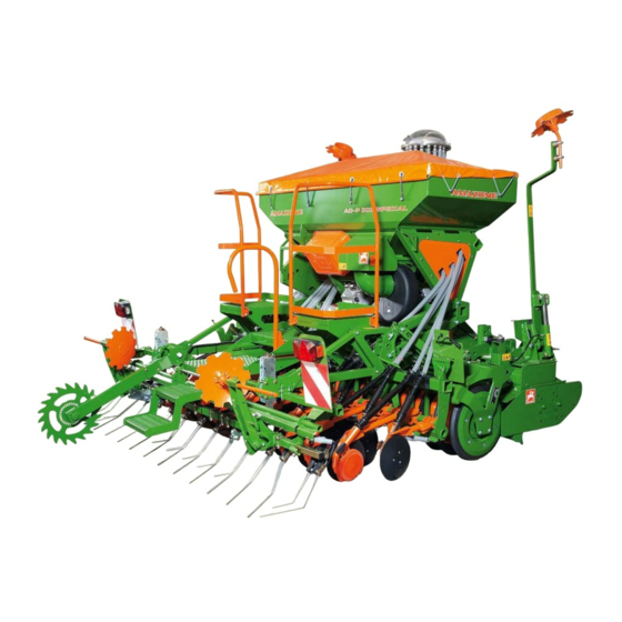
Page 36: Product Description
Product description Product description Main assemblies of the machine Fig. 7 Fig. 7/… (1) Cultivator; rotary cultivator or rotary harrow as required (2) Roller; wedge ring roller or tooth packer roller as required (3) AD-P Special top-mounted seed drill AD-P 03 Special BAH0018-5 09.14... -
Page 37: Assemblies Of The Machine
Product description Assemblies of the machine Fig. 8 Fig. 8/… (8) Exact harrow, roller harrow (as required) (1) Hopper (9) Blower fan (2) Swivelling cover (10) Loading board (3) Distributor head (11) Calibration trough (4) Dosing unit (12) Roller feeler (required for electr. dosing (5) Seed hoses drive for distance measurement) (6) Track marker (secured to cultivator) - Page 38 Product description Fig. 9 AMALOG+ control terminal (optional) Fig. 9 Fig. 10/... AMADRILL+ control terminal (optional) Fig. 10 Fig. 11 AMATRON 3 control terminal (optional) Fig. 11 Fig. 12/... Fixtures for the supply lines Fig. 12 AD-P 03 Special BAH0018-5 09.14...
- Page 39 Product description Fig. 13/... (1) Vario gearbox (2) Gearbox lever Fig. 13 Fig. 14/... (1) Seed dosing unit (2) Injector sluice Fig. 14 Fig. 15/... (1) Electric motor (with "full dosing", the electric motor drives the seed dosing roller). Fig. 15 Fig.
- Page 40 Product description Fig. 17/... WS coulter Fig. 17 Fig. 18/... Band sowing shoe II Fig. 18 Fig. 19 RoTeC control coulter Fig. 19 Fig. 20 Tramline marker Fig. 20 AD-P 03 Special BAH0018-5 09.14...
-
Page 41: Safety And Protection Equipment
Product description Safety and protection equipment Fig. 21/... (1) Chain guard Fig. 21 Fig. 22/... (1) Protective device on fan intake connection Fig. 22 Fig. 23/... (1) V-belt protector Fig. 23 Fig. 24/... (1) Positioning pin secured with lynch pin for safe transport of track marker. - Page 42 Product description Fig. 25/... (1) A riveted fixture prevents removal of the charging sieve when the dosing roller is running (only full dosing). Fig. 25 Fig. 26/... (1) Dosing window lock. Interruption of the roller drive when the dos- ing window is opened (Fig. 26/2) with full dosing.
-
Page 43: Overview - Supply Lines Between The Tractor And The Machine
Product description Overview – Supply lines between the tractor and the machine 4.4.1 Hydraulic connections • All hydraulic hose lines are equipped with grips. Coloured markings with a code number or code letter have been applied to the gripping sections in order to assign the respective hydraulic function to the pressure line of a tractor control unit! Films are stuck on the implement for the markings that illustrate the respective hydraulic function. -
Page 44: Data Cable
Product description 4.4.2 Data cable Designation Function Machine connector Connection for on-board computer 4.4.3 Power connection for road transportation Designation Function Plug (7-pin) Road traffic lighting system AD-P 03 Special BAH0018-5 09.14... -
Page 45: Transportation Equipment
Product description Transportation equipment Fig. 28/... (1) 2 rear-facing warning signs (2) 1 licence plate holder (optional) only machines with exact harrow: (3) Road safety bar, two-part Fig. 28 Fig. 29/... (1) 2 rear-facing turn indicators (2) 2 side reflectors, yellow (3) 2 brake and rear lights (4) 2 reflectors, red (5) 1 light for licence plate... - Page 46 Product description Fig. 30/... (1) 2 forwards-facing warning signs Fig. 30 Fig. 31/... (1) 2 limiting lights pointing forwards (2) 2 forwards-facing turn indicators Fig. 31 AD-P 03 Special BAH0018-5 09.14...
-
Page 47: Intended Use
• is mounted on a permitted AMAZONE cultivator • is coupled to the tractor three-point hitch together with the culti- vator and is operated by an additional person. -
Page 48: Danger Area And Danger Points
Product description Danger area and danger points The danger area is the area around the machine in which people can be caught: • by work movements made by the machine and its tools. • by materials or foreign objects ejected by the machine. •... -
Page 49: Rating Plate And Ce Mark
Product description Rating plate and CE mark The figure shows the arrangement of the rating plate and the CE mark on the machine. The CE mark indicates compliance with the stipulations of the valid EU directives. Fig. 32 The rating plate and the CE mark indicate: (1) Machine ID no. -
Page 50: Technical Data
Product description Technical Data AD-P 303 AD-P 353 AD-P 403 Special Special Special AD-P Special with hopper content 750 l 1250 l 1250 l 750 l 1250 l Working width 3.00 3.50 4.00 Transport width 3.03 3,49 4,03 [num- Number of sowing units 24/18 28/21 32/24... - Page 51 Product description Total weight (G Permissible total weight (G of the rear machine combination is the sum of the weights (see Fig. 34) of the • basic weight of the seed drill • payload of the seed drill • basic weight of the cultivator •...
-
Page 52: Necessary Tractor Equipment
Necessary tractor equipment For operation of the machine in compliance with the intended use the tractor must fulfil the following requirements. Tractor engine power AD-P 303 Special from 66 kW (90 bhp) upwards AD-P 353 Special from 81 kW (110 bhp) upwards... -
Page 53: Structure And Function
• AMAZONE rotary cultivator (Fig. 35/2) or • AMAZONE rotary harrow • AMAZONE wedge ring roller (Fig. 35/3) or • AMAZONE tooth packer roller. This cultivation combination optimises loosening of the soil, recompacting and precise drilling in a single operation. -
Page 54: Amalog+ On-Board Computer (Optional)
Structure and function AMALOG+ on-board computer (optional) The AMALOG+ on-board computer consists of • the control terminal • the basic equipment (cable and fastening material). The AMALOG+ on-board computer • is intended for entering machine-specific data before beginning work. • measures the covered part area [ha]. -
Page 55: Amadrill+ On-Board Computer (Optional)
Structure and function AMADRILL+ on-board computer (optional) The AMADRILL+ on-board computer consists of • the control terminal • the basic equipment (cable and fastening material). Fig. 37 The AMADRILL+ on-board computer • is intended for entering machine-specific data before beginning work. •... -
Page 56: Amatron 3 On-Board Computer (Optional)
Structure and function AMATRON 3 on-board computer (optional) The AMATRON 3 is an operating terminal for fertiliser spreaders, field sprayers and seed drills. The AMATRON 3 consists of • the control terminal • the basic equipment (cable and fastening material) •... -
Page 57: Hopper And Loading Board
Structure and function The AMATRON 3 • monitors the function of the overload clutch. Acoustic alarm in event of tool carrier standstill. Hopper and loading board The hopper is equipped with a swivelling cover (Fig. 39/1), which is sealed against dust and wa- ter. -
Page 58: Dosing
Structure and function Dosing The hopper has a dosing unit. The seed is metered by a dosing roller in the dosing unit. The speed of the dosing roller de- termines the sowing rate. The dosing roller (Fig. 41/1) can be replaced. The seed falls into the injector sluice (Fig. -
Page 59: Dosing Rollers
Structure and function Star wheel drive The sowing rate (speed of dosing roller) • can be adjusted on the Vario gearbox • is set by the on-board computer on the basis of the calibration test and working speed, with a Vario gearbox with electronic seed rate adjustment Full dosing The sowing rate (speed of dosing roller) -
Page 60: Overview Of Dosing Rollers
Structure and function 5.5.2 Overview of dosing rollers Dosing rollers Order no. 976731 961457 967777 Volume [cm Order no. 961456 961454 967774 Volume [cm Fig. 45 For sowing particularly large seeds, e.g. beans, the chambers (Fig. 46/1) of the dosing roller can be enlarged by repositioning the wheels and the plates. -
Page 61: Seed/Dosing Rollers Table
Structure and function Seed/dosing rollers table 5.5.3 Dosing rollers Seed 7.5 cm³ 20 cm³ 120 cm³ 210 cm³ 600 cm³ 700 cm³ Beans Spelt wheat Peas Flax (dressed) Barley Grass seed Oats Millet Lupins Alfalfa Maize Poppy seed Linseed (for oil) (moist dressing) Fodder radish Phacelia... -
Page 62: Seed Rate Adjustment At Vario Gearbox
Structure and function 5.5.4 Seed rate adjustment at Vario gearbox The sowing rate required is set using the gear- box lever (Fig. 48/1) of the Vario gearbox. Adjusting the gearbox lever changes the sowing rate. The higher the number the gearbox lever points to on the scale (Fig. -
Page 63: Seed Rate Remote Control, Hydraulic On The Vario Gearbox (Optional)
Structure and function 5.5.5 Seed rate remote control, hydraulic on the Vario gearbox (optional) The sowing rate can be adapted to the soil dur- ing drilling in the event of a change from normal soil to heavy soil and vice versa. The gearbox lever of the Vario gearbox is ad- justed by a hydraulic cylinder. -
Page 64: Seed Rate Adjustment With Full Dosing (Optional)
Structure and function 5.5.7 Seed rate adjustment with full dosing (optional) With machines with full dosing an electric motor (Fig. 52/1) drives each dosing roller. The ma- chines do not have Vario gearboxes. The rotational drive speed of the dosing roller is determined by the working speed and the preset sowing rate. - Page 65 Structure and function Start-up ramp The "start-up ramp" is adjustable, allowing the seed rate to be adapted to the machine acceleration after turning. As soon as the machine is lowered to the operational position after turning, the seed is metered into the delivery line. The "start-up ramp" compensates for system-specific seed rate reductions during the ac- celeration phase of the machine.
-
Page 66: Calibration Test
Structure and function 5.5.8 Calibration test The calibration test checks whether the pre-set and actual sowing rates are equivalent. Always carry out a calibration test • when the seed type is changed • if the seed type is identical, but the grain size, grain shape, spe- cific weight and dressing are different •... -
Page 67: Blower Fan
Structure and function Blower fan The blower fan (Fig. 55/1) generates the air cur- rent that carries the seed from the injector sluice to the sowing coulters. The blower fan is driven either • by a hydraulic motor (Fig. 55/2) connected to the tractor's on-board hydraulic system Fig. -
Page 68: Blower Fan With Hydraulic Drive
Structure and function 5.6.1 Blower fan with hydraulic drive The hydraulic motor (Fig. 58/2) drives the blower fan (Fig. 58/1). The blower fan generates an air current that car- ries the seed from the injector sluice to the coul- ters. The blower fan speed determines the air volume of the air current. -
Page 69: Blower Fan With Belt Drive
Structure and function The blower fan speed is as a rule displayed by the on-board computer. Machines without an on-board computer have a pressure gauge (Fig. 60). The blower fan speed is set correctly when the pressure gauge pointer during work •... - Page 70 Structure and function Different seed types require adjustment of the air quantity to the seed type. To reduce the air quantity, the machine has a throttle flap with throttle flap lever (Fig. 62/1). Please refer to the table (Fig. 63, unterhalb) for the throttle flap lever position.
-
Page 71: Distributor Head
Structure and function Distributor head In the distributor head (Fig. 65/1) the seed is distributed uniformly over all the sowing coulters. Fig. 65 Star wheel / Impulse wheel Via the Vario gearbox, the star wheel (Fig. 66/1) drives the dosing roller in the seed dosing unit. The star wheel can have two settings •... - Page 72 Structure and function The on-board computer requires the impulses from the mounted wheel over a calibration distance of 100 m • to calculate the forward speed • to calculate the area cultivated (hectare counter). • to adjust the spread rate. The value Impulses/100 m is the number of impulses received by the on-board computer during the measuring travel of the wheel.
-
Page 73: Ws Coulter (Optional Equipment)
Structure and function WS coulter (optional equipment) Use your seed drill with WS coulters (Fig. 69) for conventional drilling. A guide hopper (Fig. 69/1) delivers the seed im- mediately behind the coulter tip (Fig. 69/2). A precise and uniform planting depth is achieved. The hinged coulter support (Fig. -
Page 74: Rotec Control Coulter (Optional Equipment)
Structure and function 5.10 RoTeC control coulter (optional equipment) Seed drills with RoTeC control coulters (Fig. 71) are suitable for plough seeding and mulch sow- ing. The flexible depth guide disc (Fig. 71/2) • limits the seed planting depth • cleans the rear side of the sowing disc (Fig. -
Page 75: Coulter Pressure
Structure and function 5.11 Coulter pressure The planting depth depends on • the soil condition • the travel speed • the coulter pressure. The coulter pressure is adjusted centrally by means of the calibration crank or hydraulically. 5.11.1 Coulter pressure (adjusted with the calibration crank) The coulter pressure is set centrally with the cal- ibration crank (Fig. -
Page 76: Coulter Pressure Adjustment, Hydraulic (Optional)
Structure and function 5.11.2 Coulter pressure adjustment, hydraulic (optional) The coulter pressure can be adapted to the soil during drilling in the event of a change from nor- mal soil to heavy soil and vice versa. Two bolts (Fig. 74/1) in an adjuster segment act as the stop for the hydraulic cylinder. -
Page 77: Exact Harrow (Optional Equipment)
Structure and function 5.12 Exact harrow (optional equipment) The exact harrow (Fig. 75/1) evenly covers the seeds deposited in the sowing furrows with loose earth and smoothes the ground. The following are adjustable • the exact harrow tine setting ο by adjusting screws of exact harrow holder ο... -
Page 78: Exact Harrow Pressure Adjustment
Structure and function 5.12.2 Exact harrow pressure adjustment The exact harrow pressure is generated by ten- sion springs that are tensioned using a lever (Fig. 77/1). The lever is in contact with a bolt (Fig. 77/2) in the adjuster segment. The higher the pin is in- serted in the group of holes, the greater the ex- act harrow pressure. -
Page 79: Roller Harrow (Optional Equipment)
Structure and function 5.13 Roller harrow (optional equipment) The roller harrow consists of • the harrow tines (Fig. 79/1) • the press rollers (Fig. 79/2). The harrow tines close the seed furrows. The press rollers press the seed to the bottom of the furrows. -
Page 80: Creating Tramlines (Option)
Structure and function 5.15 Creating tramlines (Option) The tramline control allows tramlines to be created at preselected intervals on the field. To set the different tramline distances appropri- ate tramline rhythms have to be entered into the on-board computer. When creating the tramlines •... - Page 81 Structure and function The tramline control allows tramlines to be created at preselected intervals on the field. Tramlines are seed-free tracks (Fig. 82/A) for fertilising and plant care machines used later. The tramline spacing (Fig. 82/b) corresponds to the working width of the cultivation machines (Fig.
- Page 82 Structure and function Seed drill working width 3.0 m 3.5 m 4.0 m Tramline spacing Tramline rhythm (working width of the fertiliser spreader and field sprayer) 12 m 12 m 16 m 15 m 24 m 28 m 24 m 28 m 32 m 27 m...
-
Page 83: Examples For Creating Tramlines
Structure and function 5.15.1 Examples for creating tramlines The creation of tramlines is shown in Figure (Fig. 84) using various examples: Working width of the seed drill Tramline spacing (= working width of fertiliser spreader / field sprayer) Tramline rhythm Tramline counter (during work the field runs are number con- secutively and displayed on the on-board computer). - Page 84 Structure and function Fig. 84 AD-P 03 Special BAH0018-5 09.14...
-
Page 85: Tramline Rhythm 4, 6 And 8
Structure and function 5.15.2 Tramline rhythm 4, 6 and 8 Fig. 85 Figure (Fig. 84) shows examples for creating tramlines with the tramline rhythm 4, 6 and 8. The work of the seed drill at half working width (partial width) during the first field run is shown. Another option for creating tramlines with the tramline rhythm 4, 6 and 8 is to begin with the full work- ing width and the creation of a tramline (see Fig. -
Page 86: Tramline Control 2 And 21
Structure and function 5.15.3 Tramline control 2 and 21 Fig. 86 (Fig. 84) shows examples of creating tramlines with tramline control 2 and 21. When tramlines are created with the tramline control 2 and 21 (Fig. 86), tramlines are created during the trips forward and backward over the field. -
Page 87: Working With Half Working Width (Partial Width)
Structure and function 5.15.4 Working with half working width (partial width) The installation of an insert (Fig. 87/1) in the dis- tributor head interrupts the seed supply to the coulters of one machine half. Halve the sowing rate when working with half a working width. -
Page 88: Commissioning
Commissioning Commissioning This section contains information • on commissioning your machine • on checking how you may connect the machine to your tractor. • Before operating the machine for the first time, the operator must have read and understood the operating manual. •... -
Page 89: Checking The Suitability Of The Tractor
Commissioning Checking the suitability of the tractor WARNING Danger of breaking during operation, insufficient stability and insufficient tractor steering and braking power on improper use of the tractor! • Check the suitability of your tractor before you attach or hitch the machine to the tractor. -
Page 90: Calculating The Actual Values For The Total Tractor Weight, Tractor Axle Loads And Load Capacities, As Well As The Minimum Ballast
Commissioning 6.1.1 Calculating the actual values for the total tractor weight, tractor axle loads and load capacities, as well as the minimum ballast The permissible total tractor weight, specified in the vehicle docu- mentation, must be greater than the sum of the •... -
Page 91: Data Required For The Calculation)
Commissioning 6.1.1.1 Data required for the calculation) Fig. 89 [kg] Tractor empty weight See tractor operating manual or vehicle [kg] Front axle load of the unladen tractor documentation [kg] Rear axle load of the unladen tractor [kg] Total weight of rear-mounted machine or See section "Technical data for the calcula- rear ballast tion of tractor weights and tractor axle... -
Page 92: Of The Tractor To
Commissioning 6.1.1.2 Calculation of the required minimum ballasting at the front G of the tractor to en- V min sure steering capability • − • • • Enter the numeric value for the calculated minimum ballast G V min required on the front side of the tractor, in the table (see section 6.1.1.7). -
Page 93: Table
Commissioning 6.1.1.7 Table Actual value according to Permissible value Double approved calculation according to tractor load capacity (two instruction manual tyres) Minimum ballast front / rear Total weight ≤ Front axle load ≤ ≤ Rear axle load ≤ ≤ • You can find the approved values for the total tractor weight, axle loads and load capacities in the tractor registration papers. -
Page 94: Securing The Tractor / Machine Against Unintentional Start-Up And Rolling
Commissioning Securing the tractor / machine against unintentional start-up and roll- WARNING Risk of contusions, cutting, catching, drawing in and knocks when making interventions in the machine through • unintentional lowering of the unsecured machine when it is raised via the three-point hydraulic system of the tractor •... -
Page 95: Installation Regulations For The Hydraulic Fan Drive Connection
Commissioning Installation regulations for the hydraulic fan drive connection The banking-up pressure of 10 bar must not be exceeded. The instal- lation regulations therefore have to be complied with when connecting the hydraulic fan connection. • Connect the hydraulic coupling of the pressure hose (Fig. 90/5) to a single-acting or double-acting tractor control unit with priori- •... -
Page 96: Initial Fitting Of Coupling Parts (Specialist Workshop)
PW 500 Order no.: 964407 Order no.: 964407 Order no.: 973045 Seed drill AD-P 303 Special AD-P 353 Special AD-P 403 Special Fig. 91 1. Connect the cultivator to the tractor (see KE/KG operating manual). 2. Apply the tractor parking brake, switch off the engine and remove the ignition key. - Page 97 Commissioning The pin (Fig. 93/1) corresponds to the pin marked with an arrow in the illus- trations (Fig. 94, Fig. 96 and Fig. 98). Fig. 93 Coupling parts A - KW580/PW600 (Order no.: 964406) Fig. 94 Fig. 95 Coupling parts A - KW 520 (Order no.: 965579) Fig.
- Page 98 Commissioning Coupling parts A - PW 500 (Order no.: 964407) Fig. 98 Fig. 99 Coupling parts D - PW 500 (Order no.: 973045) Fig. 100 Fig. 101 AD-P 03 Special BAH0018-5 09.14...
-
Page 99: Initial Fitting Of Road Safety Bar Holders (Specialist Workshop)
Commissioning 6.4.1 Initial fitting of road safety bar holders (specialist workshop) 6.4.1.1 Mounting the holder on seed drills with 750 l hopper Screw the two holders (Fig. 102/1) onto the exact harrow. Fig. 102 Fig. 103 During work, secure the road safety bars (Fig. 103/1) to the holders (Fig. -
Page 100: Mounting The Holder On Seed Drills With 1250 L Hopper
Commissioning 6.4.1.2 Mounting the holder on seed drills with 1250 l hopper Screw the two holders (Fig. 102/1) onto the exact harrow (Fig. 102/2). Fig. 104 Fig. 105 During work, secure the road safety bars (Fig. 103/1) to the holders (Fig. -
Page 101: Coupling And Uncoupling The Machine
Coupling and uncoupling the machine Coupling and uncoupling the machine When coupling and uncoupling machines, follow the instructions giv- en in the section "Safety instructions for the operator". CAUTION Switch off the on-board computer • before transport • before adjustment, maintenance and repair work. Risk of accident due to unintentional movement of machine compo- nents when wheel is moved. -
Page 102: Hydraulic Hose Lines
Coupling and uncoupling the machine Hydraulic hose lines WARNING Danger of infection from escaping hydraulic fluid at high pres- sure! When coupling and uncoupling the hydraulic hose lines, ensure that the hydraulic system is depressurised on both the machine and trac- tor sides. -
Page 103: Uncoupling The Hydraulic Hose Lines
Coupling and uncoupling the machine 7.1.2 Uncoupling the hydraulic hose lines 1. Swivel the actuation lever on the control valve on the tractor to float position (neutral position). 2. Release the hydraulic connectors from the hydraulic sockets. 3. Protect the hydraulic connectors and hy- draulic connector sockets from soiling using the dust protection caps. - Page 104 Coupling and uncoupling the machine WARNING Risk of contusions, cutting, catching, drawing in and knocks when the machine unexpectedly releases from the tractor! • Use the intended equipment to connect the machines in the proper way. • Whenever you couple the machine, check the coupling parts, such as the top link pin, for visible defects.
- Page 105 Coupling and uncoupling the machine Refer to the table (Fig. 91) to see which cultivator and roller you can combine with your AD-P Special top-mounted seed drill. Note for machines with blower fan belt drive: Secure the V-belt pulley on the universal joint shaft drive-through of the cultivator (see section "Connecting blower fan belt drive", Seite 108) before coupling the top-mounted seed drill.
- Page 106 Coupling and uncoupling the machine 10. Secure all 4 catching sockets with pins (Fig. 111/1). If not used, insert the pins in the holes (Fig. 111/2) 11. Secure the pins with the lynch pins provid- Fig. 111 12. Remove the parking supports (Fig. 112/1). Fig.
- Page 107 Coupling and uncoupling the machine Only track markers secured to the cultivator: 18. Connect the track markers by connecting the hydraulic coupling (Fig. 115/1). Fig. 115 Only with blower fan belt drive: 19. Connect the blower fan belt drive (if fitted) (see section "Connecting blower fan belt drive", Seite 108).
-
Page 108: Connecting Blower Fan Belt Drive (Specialist Workshop)
Coupling and uncoupling the machine 7.2.1 Connecting blower fan belt drive (specialist workshop) Connect the blower fan belt drive only at one AMAZONE cultivator with universal joint shaft through drive. Operate the AMAZONE cultivator only with 1000 rpm tractor univer- sal joint shaft speed. - Page 109 Coupling and uncoupling the machine 6. Align the V-belt pulleys. 6.1 Release the tapered clamping bush and align the V-belt pulley (Fig. 118/1) on the shaft of the universal joint shaft drive-through with the V-belt pulley (Fig. 118/2) of the blower fan. 7.
- Page 110 Coupling and uncoupling the machine 10. Fit the V-belts (Fig. 120/1). 11. Tension the V-belts (see section "Checking/adjusting belt tension", Seite 179). Fig. 120 12. Ensure that the spring-loaded V-belt ten- sioner (Fig. 121/1) is correctly seated. Adjust the seat of the V-belt ten- sioner when coupling to another cultivator and secure with a new tension sleeve (Fig.
-
Page 111: Connecting The Pressure Gauge
Coupling and uncoupling the machine 14. Secure the blower fan V-belt protector (Fig. 123/2) with two nuts (Fig. 123/1). Fig. 123 7.2.2 Connecting the pressure gauge Connect the hose to the pressure gauge and secure the pressure gauge in the tractor cabin. Fig. -
Page 112: Uncoupling The Top-Mounted Seed Drill From The Cultivator
Coupling and uncoupling the machine Uncoupling the top-mounted seed drill from the cultivator DANGER Empty the seed hopper before decoupling the top-mounted seed drill from the cultivator. WARNING Risk of contusions, cutting, catching, drawing in and knocks through insufficient stability and possible tilting of the uncou- pled machine! Set the empty machine down on a horizontal parking area with a firm base. - Page 113 Coupling and uncoupling the machine 7. Uncouple all supply lines between the trac- tor and the machine. 8. Close the hydraulic connectors with protec- tive caps. 9. Fasten the supply lines to the mountings (Fig. 125). Fig. 125 10. Relieve the V-belts of the blower fan belt drive (if fitted) and remove (see section "Checking/adjusting belt tension", Seite 179).
- Page 114 Coupling and uncoupling the machine All types: 13. Raise the combination. 14. Apply the tractor parking brake, switch off the engine and remove the ignition key. 15. Insert the 4 parking supports (Fig. 128/1) into the square tubes of the top-mounted seed drill.
- Page 115 Coupling and uncoupling the machine 21. Direct persons out of the danger area be- tween the machines. 22. Lower the combination. The coupling triangle is released as soon as the top-mounted seed drill is on the parking supports. Fig. 131 23.
-
Page 116: Settings
Settings Settings WARNING Risk of crushing, shearing, cutting, being caught and/or drawn in, or impact through • Unintentional lowering of the machine raised using the tractor's three-point hydraulic system. • unintentional falling of raised, unsecured machine parts. • Unintentional start-up and rolling of the tractor-machine combination. - Page 117 Settings 4. Insert the charging sieves and secure with safety splints (Fig. 134/1). Fig. 134 With machines with full dosing, the charging sieves cannot be opened. The fixture (Fig. 135/1) is riveted. The level sensor is adjusted by means of an extension above the charging sieves and must be secured with a wing nut.
-
Page 118: Inserting The Dosing Roller Into The Dosing Unit
Settings Inserting the dosing roller into the dosing unit DANGER Switch off the on-board computer, turn off the tractor universal joint shaft, apply the tractor parking brake, switch off the tractor engine and remove the ignition key. 1. Remove the lynch pin (Fig. 136/2) (only necessary with full seed hopper to close the hopper with the slider) (Fig. - Page 119 Settings 3. Slacken but do not unscrew the two winged nuts (Fig. 138/1). 4. Turn the bearing cover and pull it off. Fig. 138 5. Pull the dosing roller out of the seed dosing unit. 6. Refer to table (table, Seite 61) for the re- quired dosing roller and install in the re- verse order.
-
Page 120: Steps, Transportation And Operational Position
Settings Steps, transportation and operational position Step onto the loading board via the steps. Fig. 140 Fold up the steps • before starting work • before transporting the machine on public roads. Fig. 141 AD-P 03 Special BAH0018-5 09.14... -
Page 121: Filling The Hopper
Settings Filling the hopper DANGER Connect the top-mounted seed drill to the cultivator before fill- ing the hopper. Observe the permissible fill levels and total weights. Empty the hopper before decoupling the top-mounted seed drill. WARNING Risk of crushing in danger area under suspended loads / ma- chine parts when filling the seed hopper, caused by unintention- al lowering. -
Page 122: Setting The Sowing Rate With A Calibration Test
Settings Setting the sowing rate with a calibration test 1. Park the combination on a horizontal surface 2. Disengage the tractor's universal joint shaft, engage the parking brake, shut off the engine and remove the ignition key. 3. Fill the seed hopper with at least 200 kg of seed (correspondingly less for fine seed) (see section "Filling the hopper", Seite 121). -
Page 123: Adjusting Sowing Rate With Calibration Test On Machines With Vario Gearbox Without Seed Rate Remote Control
Settings 8.5.1 Adjusting sowing rate with calibration test on machines with Vario gearbox without seed rate remote control 1. Undo the locking knob (Fig. 145/1). 2. Consult the table (Fig. 146, unterhalb) for the gearbox setting value for the first cali- bration test. - Page 124 Settings 6. Push the calibration crank handle (Fig. 148/1) onto the star wheel (Fig. 148/2). 7. Direct people out of the danger area. When the star wheel is turned, the dosing roller in the dosing housing turns. 8. Turn the star wheel with the calibration crank handle counterclockwise until all chambers of the dosing roller are filled with seed and a uniform seed stream flows into...
- Page 125 Settings 13. Weigh the volume of seed caught in the calibration trough (taking the container weight into consideration) and multiply ο by a factor of 40 (for 1/40 ha) or ο by a factor of 10 (for 1/10 ha). Check the accuracy of the scale dis- play.
-
Page 126: Determining The Gearbox Setting Using The Calculating Disc Rule
Settings 8.5.1.1 Determining the gearbox setting using the calculating disc rule Example: Values from the calibration test computed sowing rate: 175 kg/ha gearbox setting: 125 kg/ha. Desired sowing rate: 1. Line up the values from the calibration test ο Computed sowing rate 175 kg/ha (Fig. -
Page 127: Adjusting Sowing Rate With Calibration Test On Machines With Hydraulic Seed Rate Remote Control
Settings 8.5.2 Adjusting sowing rate with calibration test on machines with hydraulic seed rate remote control WARNING Direct persons away from the area of the hydraulic adjustment of Vario gearbox, coulter pressure and exact harrow pressure. Setting the normal sowing rate 1. - Page 128 Settings Setting the elevated sowing rate 1. Actuate tractor control unit blue. → Apply pressure to the hydraulic cylinder. 2. Disengage the tractor's universal joint shaft, engage the parking brake, shut off the en- gine and remove the ignition key. 3.
-
Page 129: Adjusting Sowing Rate With Calibration Test On Machines With Vario Gearbox And With Electronic Seed Rate Adjustment
Settings 8.5.3 Adjusting sowing rate with calibration test on machines with Vario gearbox and with electronic seed rate adjustment 1. Enter the desired sowing rate in the on- board computer. 2. Remove the calibration crank (Fig. 155/1) from the transport bracket. Fig. -
Page 130: Adjusting Sowing Rate With Calibration Test On Machines With Full Dosing
Settings 8.5.4 Adjusting sowing rate with calibration test on machines with full dosing 1. Adjust the desired sowing rate in the on-board computer. 1.9 Adjust the sowing rate with calibration test as described in the on-board computer operating manual. The number of engine revolutions for the calibration test until the signal tone sounds is governed by the sowing rate: 0 to 14.9 kg →... -
Page 131: Setting The Blower Fan Speed For Blower Fans With Hydraulic Drive
Settings Setting the blower fan speed for blower fans with hydraulic drive This setting is not required for blower fans with belt drive. DANGER Do not exceed the maximum blower fan speed of 4000 rpm. The blower fan speed alters until the hydraulic fluid has reached its working temperature. -
Page 132: Setting At The Pressure Relief Valve With Round Outer Contour
Settings 8.6.1 Setting at the pressure relief valve with round outer contour Fig. 157 Fig. 158 8.6.1.1 Setting the blower fan speed via the flow control valve of the tractor 1. Loosen the lock nut (Fig. 157). 2. Adjust the pressure relief valve to the factory-set dimension "21 mm" (Fig. 158). 2.1 Turn the screw with the hexagon socket wrench accordingly. -
Page 133: Setting At The Pressure Relief Valve With Hexagon Outer Contour
Settings 8.6.2 Setting at the pressure relief valve with hexagon outer contour Fig. 159 Fig. 160 8.6.2.1 Setting the blower fan speed via the flow control valve of the tractor 1. Loosen the lock nut (Fig. 159). 2. Screw in the screw (Fig. 160) with the hexagon socket wrench fully (clockwise). 3. -
Page 134: Setting The Blower Fan With Belt Drive
Settings Setting the blower fan with belt drive 1 Set the speed at the universal joint shaft through drive of the cultivator to 1000 rpm. 2. Set the throttle flap lever (Fig. 161/1) as per the table (Fig. 63, Seite 70). Fig. -
Page 135: Adjusting Coulter Pressure / Seed Placement Depth
Settings Adjusting coulter pressure / seed placement depth This setting influences the planting depth of the seed. Check the planting depth every adjustment (see section "Checking the placement depth of the seed", Seite 161). 8.8.1 Setting the coulter pressure (mechanical coulter pressure adjustment) 1. -
Page 136: Adjusting The Depth Guide Discs
Settings 8.8.3 Adjusting the depth guide discs This setting influences the planting depth of the seed. Check the planting depth of the seed after each adjustment. If the desired placement depth cannot be achieved by adjusting the coulter pressure, adjust all depth guide discs evenly. Each depth guide disc can engage in three positions on the coulter or be removed from the coulter. - Page 137 Settings Sowing without depth guide disc 1. Turn the handle beyond the engagement catch (Fig. 167/1) and remove the depth guide disc from the coulter. Fig. 167 Fitting the depth guide disc Secure the depth guide disc with the marking •...
-
Page 138: Adjusting The Exact Harrow
Settings Adjusting the exact harrow 8.9.1 Exact harrow tine position The exact harrow tine position is adjustable (see Table Fig. 76) • by adjusting screws of exact harrow holder • via a spindle (optional) Setting exact harrow tine position by adjusting screws of exact harrow holder 1. - Page 139 Settings Exact harrow tine setting by adjusting spindles (optional) 1. Move the machine on the field to the work- ing position. 2. Apply the tractor parking brake, switch off the engine and remove the ignition key. 3. Set the exact harrow tines as per table (Fig.
-
Page 140: Exact Harrow Pressure Adjustment
Settings 8.9.2 Exact harrow pressure adjustment 1. Tension the lever (Fig. 171/1) with the cali- bration crank. 2. Insert the pin (Fig. 171/2) into a hole below the lever 3. Relieve the lever. 4. Secure the bolt with a safety splint. 5. -
Page 141: Moving The Exact Harrow To The Working / Transport Position
Settings 8.9.4 Moving the exact harrow to the working / transport position Working position The roller and the coulters force the soil out- wards to different extents depending on the trav- el speed and condition of the soil. Set the outer harrow such that the soil is guided back and a trackless seed bed is created. -
Page 142: Adjusting The Roller Harrow
Settings 8.10 Adjusting the roller harrow DANGER Before adjustment, switch off the tractor's universal joint shaft, apply the parking brake, shut down the tractor engine and re- move the ignition key. 8.10.1 Setting harrow tines (roller harrow with upper guide bar) To adjust the harrow tines, raise the machine so that the harrow tines are directly above the soil but not touching it. -
Page 143: Adjusting Harrow Tines (Roller Harrow With Carrier Handle)
Settings 8.10.2 Adjusting harrow tines (roller harrow with carrier handle) To adjust the harrow tines, raise the machine so that the harrow tines are directly above the soil but not touching it. Apply the tractor parking brake, switch off the engine and remove the ignition key. 8.10.2.1 Adjusting the angle of the harrow tines 1. -
Page 144: Adjusting The Roller Contact Pressure To The Soil And Checking
Settings 8.10.3 Adjusting the roller contact pressure to the soil and checking 1. Move the machine on the field to the work- ing position. 2. The roller pressure is adjusted by turning the crank (Fig. 178/1) evenly at all four ad- juster segments. -
Page 145: Moving The Track Marker To The Working / Transport Position
Settings 8.11 Moving the track marker to the working / transport position DANGER Unsecured track markers could unintentionally move to the working position and cause serious injury. Move the track markers immediately after work on the field to the transport position and secure with lynch pins. Do not release the securing pin (lynch pin) until just before starting work in the field. - Page 146 4.7 Tighten screws (Fig. 182/1). Fig. 182 Working width Distance A AD-P 303 Special 3.0 m AD-P 353 Special 3.5 m AD-P 403 Special 4.0 m Distance from the centre of the machine to the contact area of the track marker disc Fig.
-
Page 147: Move Track Marker To Transport Position
Settings 8.11.2 Move track marker to transport position 1. Direct people out of the swivel area of the track marker. 2. Actuate tractor control unit 1. → Both track markers swivel to the transport position (see Fig. 184). 3. Apply the handbrake, switch the tractor en- gine off and remove the ignition key. -
Page 148: Setting The Tramline Rhythm/Counter On The On-Board Computer
Settings 8.12 Setting the tramline rhythm/counter on the on-board computer 1. Select the tramline rhythm (see table Fig. 83, Seite 82) and ad- just in the on-board computer (see on-board computer operating manual). 2. Take the reading of the tramline counter for the first field run in the illustration (Fig. -
Page 149: Moving The Tramline Marker To The Working / Transport Position
Settings 8.13 Moving the tramline marker to the working / transport position DANGER Direct persons away from the swivel area of the tramline mark- er before operating spool valve 1. 8.13.1 Move the tramline marker to working position 1. Secure the track disc carrier (Fig. 187/1). 2. -
Page 150: Move The Tramline Marker To Transport Position
Settings 11. Set the track discs so that they mark the tramline created by the tramline coulters. 12. Adapt the work intensity to the soil by turn- ing the discs (position the discs on light soils roughly parallel to the direction of travel and on heavy soils more on in a for- ward position). -
Page 151: Attaching The Band Sowing Shoe To The Ws Coulter
Settings 8.14 Attaching the band sowing shoe to the WS coulter Fix the band sowing shoe (Fig. 190/1) to the WS coulter with a bolt and secure with a lynch pin. Fig. 190 8.15 Road safety bar 8.15.1 Road safety bar in road transport position 1. -
Page 152: Moving The Star Wheel Into Transport/Operational Position
Settings 8.16 Moving the star wheel into transport/operational position 8.16.1 Move the star wheel to the transport position In the transport position, the star wheel (Fig. 193/1) is inserted in the transport bracket and secured with a lynch pin (Fig. 193/2). WARNING The extended star wheel protrudes sideways into the line of traffic dur-... - Page 153 Settings 2. Withdraw the star wheel out of the transport bracket. Fig. 195 3. Lower the star wheel to the operational po- sition. Fig. 196 4. Attach the chain (Fig. 197/1) Fig. 197 AD-P 03 Special BAH0018-5 09.14...
-
Page 154: Moving The Impulse Wheel Into Transport/Operational Position
Settings 8.17 Moving the impulse wheel into transport/operational position 8.17.1 Moving the impulse wheel to working position The lever (Fig. 200/1) locks the raised impulse wheel in the transport position. 1. Hold the impulse wheel firmly. 2. Actuate the lever (Fig. 200/1). 3. -
Page 155: Transportation
Transportation Transportation DANGER Transporting the combination consisting of cultivator, roller and top-mounted seed drill over 3.0 m wide mounted on the tractor is not permitted on public roads and paths in Germany and some other countries. Transport of a machine combination over 3.0 m wide is only permitted on a transport vehicle in these countries. -
Page 156: Legal Regulations And Safety
Transportation Legal regulations and safety When driving on public roads and ways the tractor and machine must comply with the national road traffic regulations (in Germany the StVZO and the StVO) and the accident prevention regulations (in Germany those of the industrial injury mutual insurance organisation). The vehicle keeper and driver are responsible for compliance with the statutory stipulations. - Page 157 Transportation DANGER Risk of personal injury from cutting and impacts caused by unin- tentional lowering of the track marker during transportation. Perform a visual inspection before transportation to check whether the track markers are secured in the transport position with the origi- nal lynch pins to prevent unintentional lowering (see section "Moving the track marker to the working / transport position", Seite 145).
- Page 158 Transportation DANGER Switch off the on-board computer during transportation. DANGER Disable the tractor control units during transport! WARNING During transportation, risk of stabbing injuries to other road us- ers from uncovered, sharp spring tines of the exact harrow pointing backwards. Transportation without a correctly fitted transport guard rail is forbid- den.
-
Page 159: Use Of The Machine
Use of the machine Use of the machine When using the machine, refer to • the section "Warning symbols and other labels on the machine" • the section "Safety instructions for the operator" It is important to observe these sections in the interests of your safety. WARNING Only actuate the tractor control units from inside the tractor cab! WARNING... -
Page 160: Preparing The Machine For Use
Use of the machine 10.1 Preparing the machine for use 1. Remove the road safety bar (see section "Road safety bar in park position",Seite 151). 2. Put the outer harrow elements of the exact harrow in working position (see section "Moving the exact harrow to the working / transport position", Seite 141). 3. -
Page 161: Checks
Use of the machine 10.3 Checks Checks to be carried out • after the first 100 m travelled at working speed • on a change from light soil to heavy soil and vice versa • after every coulter pressure adjustment •... -
Page 162: During The Work
Use of the machine 10.4 During the work 10.4.1 Switching off the tramline counter (STOP button) The shifting on of the tramline counter is prevented by actuating the STOP button of the on-board computer before folding in the active track marker before an obstacle. When the Stop button is actuated •... -
Page 163: Turning At End Of The Field
Use of the machine 10.5 Turning at end of the field Before turning at the end of the field 1. Operate control unit 1. → Raise the active track marker → Advance the tramline counter. 2. Operate the control unit for the tractor lower link. →... -
Page 164: End Of Work In The Field
Use of the machine 10.6 End of work in the field At the end of work put the machine in its transport position: 1. Switch off the blower fan. 2. If the tramline counter is to be prevented from shifting while the track marker is raised, press the STOP button (see operating manual for on-board computer). -
Page 165: Emptying The Hopper And/Or Seed Dosing Unit
Use of the machine 10.7 Emptying the hopper and/or seed dosing unit 10.7.1 Emptying the hopper 1. Apply the tractor parking brake, switch off the engine and re- move the ignition key. 2. Open the shutter (Fig. 202) and empty the seed into the calibration trough or a suitable hopper. - Page 166 Use of the machine 2. Close the shutter (Fig. 203/1) only if the seed dosing unit and not the hopper is to be emptied (see section "Inserting the dosing roller into the dosing unit", Seite 118). Fig. 203 3. Place the calibration trough under the seed dosing unit.
- Page 167 Use of the machine 5. Open the residue emptying flap (Fig. 205/1) by turning the handle (Fig. 205/2). Fig. 205 6. Turn the star wheel (Fig. 206), as in the calibration test with the calibration crank, counterclockwise until the dosing roller and seed dosing unit are completely emptied.
-
Page 168: Faults
Faults Faults WARNING Risk of crushing, shearing, cutting, being caught and/or drawn in, or impact through • Unintentional lowering of the machine raised using the tractor's three-point hydraulic system. • unintentional falling of raised, unsecured machine parts. • Unintentional start-up and rolling of the tractor-machine combination. -
Page 169: Deviations Between The Preset And Actual Sowing Rates
Faults 11.3 Deviations between the preset and actual sowing rates Possible causes and remedies of deviation between set and actual sowing rate: • The slippage of the star wheel can alter during operation, e.g. when changing from light to heavy soil. (see section "11.3.1", Seite 170). -
Page 170: Slippage Of The Star Wheel
Faults 11.3.1 Slippage of the star wheel The slippage of the star wheel can alter during operation, e.g. when changing from light to heavy soil. Only seed drills with Vario gearbox without electronic gearbox adjustment The number of crank revolutions on the star wheel for the determina- tion of the gearbox setting must then be redetermined. -
Page 171: Cleaning, Maintenance And Repairs
Cleaning, maintenance and repairs Cleaning, maintenance and repairs 12.1 Safety WARNING Risk of crushing, shearing, cutting, being caught and/or drawn in, or impact through • Unintentional lowering of the machine raised using the trac- tor's three-point hydraulic system. • unintentional falling of raised, unsecured machine parts. •... -
Page 172: Cleaning
Cleaning, maintenance and repairs 12.2 Cleaning DANGER Dressing dust is toxic and must not be inhaled or come into con- tact with the body. When emptying the hopper and dosing housing or when removing toxic dressing dust, e.g. with compressed air, wear a protective suit, protective mask, safety glasses and gloves. -
Page 173: Cleaning The Distributor Head (Specialist Workshop)
Cleaning, maintenance and repairs 12.2.1 Cleaning the distributor head (specialist workshop) WARNING Risk of contact with or inhalation of toxic dressing dust when cleaning the distributor head with compressed air. This can result in serious injury to the eyes and breathing organs. Wear a breathing mask and safety glasses when cleaning the distrib- utor head. -
Page 174: Shutdown Of The Machine Over A Long Period Of Time
Cleaning, maintenance and repairs 12.2.2 Shutdown of the machine over a long period of time 1. Thoroughly clean and dry the RoTeC control coulters. 2. To prevent rust, conserve the sowing discs with an environment-friendly anti-corrosion agent. 12.3 Lubrication regulations WARNING Before lubricating, •... -
Page 175: Lubricants
Cleaning, maintenance and repairs 12.3.1 Lubricants For lubrication work use a lithium saponified multipurpose grease with EP additives: Company Lubricant designation ARAL Aralub HL2 FINA Marson L2 ESSO Beacon 2 SHELL Retinax A 12.3.2 Lubrication points – overview Number of lu- Lubrication in- AD-P Special brication nip-... -
Page 176: Service Plan - Overview
Cleaning, maintenance and repairs 12.4 Service plan – overview Carry out maintenance work when the first interval is reached. The times, continuous services or maintenance intervals of any third party documentation shall have priority. Specialist Inspect and service the hydraulic Section Before initial opera- workshop... -
Page 177: Visual Inspection Of The Upper And Lower Link Pins
Cleaning, maintenance and repairs Specialist Inspect and service the hydraulic Section 12.4.6 Each week workshop hose lines. (at least every This inspection has to be recorded 50 operating hours) by the operator. Checking the oil level in the Vario Section 12.4.3 gearbox Checking/adjusting belt tension Section 12.4.5... -
Page 178: Checking The Oil Level In The Vario Gearbox
Cleaning, maintenance and repairs 12.4.3 Checking the oil level in the Vario gearbox 1. Position the machine on a horizontal sur- face. 2. Check the oil level. The oil level must be visible in the oil sight glass (Fig. 215/1). There is no need to change the oil. -
Page 179: Checking/Adjusting Belt Tension (Blower Fan Belt Drive)
Cleaning, maintenance and repairs 12.4.5 Checking/adjusting belt tension (blower fan belt drive) The blower fan of the AD-P SPECIAL is driven by two V-belts. The V- belts must have the specified belt tension. 1. Apply the tractor parking brake, switch off the engine and remove the ignition key. -
Page 180: Inspection Criteria For Hydraulic Hose Lines
Cleaning, maintenance and repairs 12.4.6 Inspection criteria for hydraulic hose lines Have the hydraulic hose lines replaced by a specialist workshop if during inspection you note the following criteria: • Damage to the outer layer up to the ply (e.g. scouring points, cuts, cracks). •... -
Page 181: 12.4.6.1 Labelling Hydraulic Hose Lines
• Replace the hydraulic hose lines if damaged or worn. Only use our original AMAZONE hydraulic hose lines. • The hydraulic hose lines should not be used for longer than six years, including any storage time of maximum two years. Even... -
Page 182: 12.4.6.2 Installation And Removal Of Hydraulic Hose Lines
When installing and removing hydraulic hose lines, always observe the following information: • Only a specialist workshop should carry out work on the hydrau- lic system. Only use original AMAZONE hydraulic hose lines • • Ensure cleanliness. • You must always install the hydraulic hose lines so that, in all states of operation: ο... -
Page 183: Specialist Workshop Adjustment Work
Cleaning, maintenance and repairs 12.5 Specialist workshop adjustment work 12.5.1 Adjusting the track width of the cultivating tractor (specialist workshop) When the machine is delivered or when buying a new cultivating tractor, check that the tramline is set to the track width (Fig. 221/a) of the cultivat- ing tractor. -
Page 184: Adjusting The Track Width Of The Cultivating Tractor (Specialist Workshop)
Cleaning, maintenance and repairs 12.5.2 Adjusting the track width of the cultivating tractor (specialist workshop) When the machine is delivered or when buying a new cultivating tractor, check that the tramline is set to the track width (Fig. 223/a) of the tractor. With an increasing number of adjacent tramline coulters, the track (Fig. - Page 185 Cleaning, maintenance and repairs Activating the flap The counter of the tramline control must not be at "zero". 1. Shift on the counter of the tramline control in the on-board computer if the counter is at "zero". 2. Push up the assembly window (Fig. 225/1) and take out of the flap box from the front.
-
Page 186: Switch The Chain Wheels In Chain Drive (Specialist Workshop)
Cleaning, maintenance and repairs 12.5.3 Switch the chain wheels in chain drive (specialist workshop) only machines with full dosing 1. Remove the chain guard (Fig. 227/1). 2. Release the chain tensioner (Fig. 227/2). 3. Replace the chain wheels (see table Fig. 228). -
Page 187: Handling The Tapered Clamping Bushes For V-Belt Pulleys
Cleaning, maintenance and repairs 12.5.4 Handling the tapered clamping bushes for V-belt pulleys Securing the V-belt pulley with tapered clamping bush 1. Clean all bare surfaces of the tapered clamping bush (Fig. 229/1), and the tapered bore of the V-belt pulley (Fig. 229/2). 2. -
Page 188: Screw Tightening Torques
Cleaning, maintenance and repairs 12.6 Screw tightening torques Tightening torques [Nm] Width across depending on the quality of the nuts/bolts Thread flats [mm] 10.9 12.9 M 8x1 M 10 16 (17) M 10x1 M 12 18 (19) M 12x1.5 M 14 M 14x1.5 M 16 M 16x1.5... -
Page 189: Hydraulic System Diagrams
Hydraulic system diagrams Hydraulic system diagrams 13.1 Hydraulic plan for AD-P 303 Special / AD-P 403 Special Fig. 231/… Designation Tramline marker Track marker left Track marker right Coulter pressure adjustment Exact harrow pressure adjustment Seed rate remote adjustment Track eradicator shuttle valve electro.-hydr. - Page 190 Hydraulic system diagrams Fig. 231 AD-P 03 Special BAH0018-5 09.14...
- Page 192 + 49 (0) 5405 501-0 D-49202 Hasbergen-Gaste Fax: + 49 (0) 5405 501-234 Germany e-mail: amazone@amazone.de http:// www.amazone.de Plants: D-27794 Hude • D-04249 Leipzig • F-57602 Forbach Branches in England and France Manufacturers of mineral fertiliser spreaders, field sprayers, seed drills, soil cultivation machines and communal units...
Need help?
Do you have a question about the AD-P 303 Special and is the answer not in the manual?
Questions and answers