Table of Contents
Advertisement
Quick Links
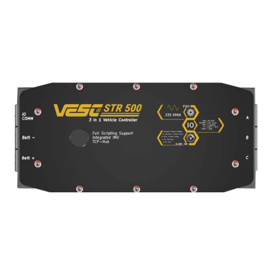
STR-500 Vehicle Controller
1 Feature overview
Voltage: 24V – 92V (Safe for 6S to 22S LiPo).
●
Optimal performance at 20S LiIon
Voltage spikes may not exceed 100V
●
Current: Continuous 500A, peak 680A. Values
●
depend on the temperature, switching frequency and
cooling of the device!
1x 5V 0,5A output for external electronics
●
1x switchable 5V 3A output for external electronics
●
5x switchable and variable 6-24V (15A combined)
●
1x static output, variable 6-24V
●
3.3V 0,5A output for external electronics
●
9 axis IMU
●
Modes: DC, BLDC, FOC (sinusoidal)
●
Supported sensors: ABI, HALL, AS5047, SIN/COS
●
and other encoders
2 Applications
Controller for light electric vehicles
●
Non street legal if not homologated
●
For integration into VESC ecosystem
●
Page 1
Page 1
3 Description
The VESC STR 500 is a versatile three-in-one vehicle controller
designed primarily for use in light electric vehicles such as
electric motorbikes, boats, karts, and similar applications. It
incorporates a microprocessor-controlled DC-DC converter to
generate auxiliary power for the vehicle's electronics.
Apart from the DC-DC converter, the STR 500 is equipped with
IO functionality for controlling inputs and outputs. This feature
enables direct control of various vehicle-mounted equipment,
including lights, blinkers, a horn, and more. Additionally, the
STR 500 includes a logging module for continuous recording
onto a Micro SD-Card and supports GPS antenna connectivity.
For accessibility, the device offers wireless connections through
BLE and WiFi. The STR 500 is supported by the VESC-Tool,
compatible with Linux, Windows, iOS, MacOS, and Android. Its
features encompass a broad range of adjustments for controller
setup and operation, along with real-time monitoring and
logging capabilities on a computer or directly onto the STR 500
itself.
4 Typical installation
The typical installation is shown in the diagram below.
It is necessary to use appropriate fuses on the battery
connection, matching the current flow in the system.
The battery needs to be managed by a suitable battery
management system (BMS). The BMS should control a
contactor on the positive discharge wire.
Rev. 1.1
Advertisement
Table of Contents

Summary of Contents for TRAMPA VESC STR 500
- Page 1 STR-500 Vehicle Controller 3 Description 1 Feature overview The VESC STR 500 is a versatile three-in-one vehicle controller Voltage: 24V – 92V (Safe for 6S to 22S LiPo). ● designed primarily for use in light electric vehicles such as Optimal performance at 20S LiIon electric motorbikes, boats, karts, and similar applications.
-
Page 2: Table Of Contents
STR 500 Vehicle Controller Table of Content 1 Feature overview………………………… ● 2 Applications………………………………. ● 3 Description………………….……………. ● 4 Typical installation……………...………. ● 5 Warnings…………………………….……. ● 6 Type of batteries……...…………………. ● 7 Pre-Charge…………….…………………. ● 8 Vehicle storage / parking………………. ● 9 Charge process of vehicles…………... ●... -
Page 3: Warnings
WARNING: Protection circuits must be installed in safety, operation and maintenance. It is essential to read between the battery and the VESC STR 500 and follow all the instructions and warnings in the controller. This includes a current flow controlled manual, prior to assembly, setup or use, in order to contactor and fuse. -
Page 4: Attaching The Motor & Battery Cables
STR 500 Vehicle Controller 10 Attaching the motor and battery cables Make sure to use appropriate wire gauge for the application and expected current flow. The cable entry grommets are available in different sizes to assure a perfect IP 67 rated sealing of the housing. Make sure to choose the correct size for your wire gauge. -
Page 5: Io-Board Connections
STR 500 Vehicle Controller 11 IO-Board connections The below diagram shows the connections on the IO-Board. Mating wire connectors: - 1,2,3,4,5,9,12: JST PH series - 8: Ultra-Fit 172258 - 11 : JST PA series BE-280 GPS Antenna 12 Hibernation switch attachment The STR500 can be used in combination with a Normally Closed (NC) switch setting the device into a ultra low power sleep mode. -
Page 6: Avoiding Ground Loops
STR 500 Vehicle Controller 13 Avoiding ground loops Ground loops will damage your devices. Follow the guidelines below to prevent loops. Page 6 Rev. 1.1... -
Page 7: Switchable Outputs
14 Connectors and Pins The VESC STR 500 controller is equipped with USB, CAN-Bus, PWM, COMM, SWD, ADC and a Sensor port. The following List will give you an idea how to interconnect the VESC STR 500 controller to other devices. -
Page 8: Software - Beta Tool
The VESC STR 500 is very new and needs to use BETA FIRMWARE until VESC-Tool 6.05 is released. The VESC STR 500 will already have the correct firmware installed but can only be configured using the beta version of the VESC tool. -
Page 9: Saturating Motors
STR 500 Vehicle Controller 17.1 Software The STR 500 is fully supported by the official VESC-Tool software package, either in App format or desktop version. Use the AutoConnect button or Scan button to find your device and establish a connection. Download VESC Tool from https://vesc-project.com/vesc_tool or the Apple App Store or Google Play Store. -
Page 10: Example
STR 500 Vehicle Controller 17.3 Example for motor tuning for ebike Talaria SUR-RON or similar. ®, ® The below image shows you the standard detection parameters from a Talaria Sting bike with stock motor ® The below image shows you the tweaked parameters for a Talaria Sting bike with stock motor. The Resistance value was upped by roughly 5%: 5,1mΩ... -
Page 11: Increased Current Settings
STR 500 Vehicle Controller 17.4 Increased current settings for example setup The below image shows you the standard detection parameters from a Talaria ® Sting bike with stock motor. The Motor Current Max value was adjusted to 400A. This value might be carefully increased to 450A. The Motor Current Max Brake was set to -60A The Absolute MAX (ABS) was set to 600A The Battery Current Max was set to 120A... -
Page 12: Software - Dc-Dc
STR 500 Vehicle Controller 17.5 Software – DC-DC programming There is a 15a DC-DC converter built inside the STR 500. This device is connected via CANBUS and has it’s own micro processor which can be configured using the VESC tool. Please follow the guide below to adjust and set the output voltage of the DC-DC converter. -
Page 13: Technical Data Sheet
STR 500 Vehicle Controller 19 Technical Data Sheet - Voltage: 24V – 92V (Safe for 6S to 22S LiPo). Recommended usage at 20S LiIon - Voltage spikes may not exceed 100V - Current: Continuous 500A, peak 680A. Values depend on the temperature, switching frequency and cooling of the device! - 1x 5V 0,5A output for external electronics - 1x switchable 5V 3A output for external electronics - 5x switchable and variable 6-24V (15A combined) -
Page 14: Integration In Your Vehicle
STR 500 Vehicle Controller 21 Integration in your vehicle Warning: The VESC STR 500 should be carefully integrated into the vehicle. Wrong assembly and placement may cause issues resulting in an unsafe operation with the probability of property damage, collateral damage, and...
Need help?
Do you have a question about the VESC STR 500 and is the answer not in the manual?
Questions and answers